1040
IEEE JOURNAL ON SELECTED AREAS IN COMMUNICATIONS, VOL. 16, NO. 7, SEPTEMBER 1998
Passive Optical Network Architecture Based on Waveguide Grating Routers Dhritiman Banerjee, Student Member, IEEE, Jeremy Frank, and Biswanath Mukherjee, Member, IEEE
Abstract— We explore an optical network architecture which employs dense wavelength division multiplexing (WDM) technology and passive waveguide grating routers (WGR’s) to establish a virtual topology based on lightpath communication. We examine the motivation and the technical challenges involved in this approach, propose and examine the characteristics of a network design algorithm, and provide some illustrative performance results. Index Terms— Lightpath, passive optical network, waveguide grating router, wavelength routing.
I. NETWORK ARCHITECTURE
(a)
A
WAVELENGTH-ROUTED optical network employs alloptical channels (lightpaths) on multiple wavelengths to establish a rearrangeable transport layer (virtual topology)1 [4], [9], [10], [7], [14], [2], [19], [21]. A lightpath may span multiple fiber links, and may need to be optically routed at an intermediate node without undergoing electronic conversion. For example, in Fig. 1, an A D optical lightpath may be established connecting nodes A and D, while simultaneously coexisting with another lightpath B E. Since both lightpaths traverse common fiber links BC and CD, the lightpaths must necessarily be operated on different wavelengths.2 A routing node in this wavelength-routed network architecture (Fig. 2) consists of an optical component for wavelength routing of all-optical lightpaths, and an electronic component for origination and termination of lightpaths, viz., electronic add-drop multiplexing, and for electronic switching (traffic forwarding) between lightpaths [4], [14], [2], [19], [21]. We employ a waveguide grating router (WGR) [11] as a passive wavelength router in the optical subcomponent of the routing node (see Fig. 2). This WGR-based network architecture has a number of advantages such as easy fabrication and commercial availability of the WGR, and complete passivity of optical components in the network with active components (switching functionality) relegated to the edges of the network (end nodes). Based on these and other advantages (discussed in Manuscript received July 1, 1998; revised April 1998. This work was supported in part by the National Science Foundation under Grants NCR92-05755 and NCR-95-08239. The authors are with the Department of Computer Science, University of California, Davis, CA 95616 USA (e-mail:
[email protected];
[email protected];
[email protected]). Publisher Item Identifier S 0733-8716(98)05742-4. 1 Since WDM optical communications has become quite popular, we refrain from providing an introduction to WDM and wavelength routing in order to conserve space. 2 We are not considering wavelength conversion [16] in this study.
(b) Fig. 1. Routing constraint in a WGR-based network.
more detail in Section III), a WGR-based network architecture has strong potential for future metropolitan and wide area networks (MAN’s and WAN’s) (as evidenced by excitement at the recently concluded Optical Fiber Communication (OFC) conference [20]). WGR [Fig. 1(b)] provides complete connectivity An between every input and output port, by passively routing optical connections on wavelengths, e.g., in Fig. 1(b), input port 2 is connected to output port 3 on wavelength . A WGR has a fixed cyclical-permutation-based routing matrix (interconnection pattern) between its input and output ports; e.g., wavelength on input port is always routed to the same modulo . wavelength on output port
0733–8716/98$10.00 1998 IEEE
BANERJEE et al.: PASSIVE OPTICAL NETWORK ARCHITECTURE BASED ON WAVEGUIDE GRATING ROUTERS
1041
Fig. 2. Routing node architecture.
The physical topology of the network that we are considering here is a mesh-connected3 fiber plant with WGR-based routing nodes. Unidirectional fiber links connect the routing nodes, i.e., a fiber connects an output port of a node’s WGR to an input port of an adjacent node’s WGR. Selection of the above output and input ports to establish a fiber link to connect adjacent nodes is an extremely important part of the network design process. Depending on these port assignments of the different fiber links and on the routes selected by the lightpath routing algorithm to route each lightpath, the wavelength assigned to each lightpath is also automatically established; e.g., in Fig. 1, a lightpath from node B (or upstream) to node D (or further downstream) via node C can only be established (since node B is connected to node C’s input on wavelength port , while node D is connected to node C’s output port ). The lightpath would have been established on wavelength if node B was connected by fiber to input port of node C. We employ WGR’s of the same uniform size at all nodes WGR in a routing node, in the network. If we use an and a particular node is connected to only neighboring nodes ports of the WGR at that through physical fibers, then particular node are free and they may be used as access ports to originate and terminate lightpaths. Each input access port -wavelength optical laser array, while is connected to an -wavelength receiver each output port is connected to an array. The laser array or the receiver array has an electronic interface which interfaces with an electronic switch (shown as an ATM switch in Fig. 2). The proposed architecture is completely passive, with active components present only at the periphery of the network. This generates a highly fault-tolerant architecture.
We provide reconfiguration capabilities in the network by introducing mechanical crossbar switches (which can be implemented using a patch panel) at the input and the output ports of the WGR. Each crossbar switch can be used to connect an incoming (outgoing) fiber to any of the input (output) ports of the WGR; this provides the network with the ability to rearrange its virtual topology in order to adapt to changing traffic demands by adjusting the fiber-to-port interconnection patterns. We assume that adjacent nodes are connected by fiber bundles (the justification is provided in Section III) and utilize this feature in the design of the network. We propose an algorithm for lightpath establishment in this optical network, which attempts to maximize the number of single-hop connections4 that may be established in the network by appropriately adjusting the crossbar switches (introduced in the previous paragraph) for a given physical network topology. It is shown that a dense virtual topology may be established, which consequently minimizes the number of lightpaths (electronic hops) a packet has to traverse to travel from a source node to a destination node. The architecture is shown to scale well with an increasing number of nodes. We believe that this is an attractive architecture for interconnecting central offices (CO’s) in future telecommunications networks. Section II discusses enabling technologies and corresponding previous work on network designs and analysis based on WGR’s. The knowledgeable reader may skip Section II. Section III provides the motivation for this research, examines some of the technical challenges present in the design of meshconnected WGR-based networks and illustrates an example of a simple network employing WGR’s as passive optical
3 A structure or graph employed to interconnect a number of nodes, possibly computers or processing elements, is known as a mesh, and it is referred to as irregular if it does not possess any well-defined connectivity pattern.
4 A single-hop connection allows nodes which may not be adjacent in the physical topology to be adjacent (i.e., directly connected by a lightpath) in the virtual topology.
1042
IEEE JOURNAL ON SELECTED AREAS IN COMMUNICATIONS, VOL. 16, NO. 7, SEPTEMBER 1998
Fig. 3. A waveguide grating router.
routers. The complete network design problem is formulated in Section IV. We employ a heuristic algorithm to solve the problem and provide numerical results to demonstrate the performance of some representative networks in Section V. Section VI concludes the paper and discusses areas of future work. II. ENABLING TECHNOLOGIES AND PREVIOUS WORK A. WGR A WGR is a passive static wavelength-routing device that has received considerable attention in the literature [11], [20]. The WGR consists of two passive star couplers connected by waveguides (fibers) of appropriate lengths (see Fig. 3). inputs and outputs, where The input star coupler has . The output star coupler is a reciprocal device, i.e., inputs and outputs. In the first star coupler, a it has signal on a given wavelength entering from any of the input waveguides. The signal ports is split and transmitted to the travels through the waveguides experiencing a different phase shift in each waveguide ( ) which depends on the length of the waveguides and the wavelength of the signal. At the input of the second star coupler, the phase difference in the signal will be such that the signal will constructively recombine only at a single output port. Two signals of the same wavelength arriving from two different input ports will not interfere with each other in the connecting waveguides because there is an additional phase difference created by the distance between the two input ports. The two signals will be combined in the waveguides, but will be separated out again in the second star coupler and directed to different output ports.
A WGR may be made periodic with wavelength; i.e., corresponding wavelengths in each period follow the same routing pattern. The wavelength span of one period is called the free spectral range (FSR). Various tradeoffs can be made regarding passband characteristics, crosstalk, etc., and some of these influence the periodicity of the router. A 15 15 WGR has been demonstrated on InP with an FSR of 10.5 nm and channel spacing of 0.7 nm in the 1550-nm region. The on-chip insertion loss is 2–4 dB, and the measured crosstalk is less than 18 dB, with the residual crosstalk less than 25 dB [11]. B. Laser Arrays Semiconductor laser arrays have been demonstrated for WDM lightwave communication systems [23]. The imple1 laser array combining mentation in [23] uses a 16 16 distributed Bragg reflector (DBR) lasers with different optical wavelengths into a single output waveguide. The implementation is able to achieve 16 different wavelengths, from 1544 to 1553 nm, with an average channel spacing of approximately 0.6 nm, which is suitable for dense WDM applications [23]. C. Previous Work WGR’s have been used in the design of access networks router [12], [15], [25]. One such architecture uses a downstream nodes [15]. The to connect a headend node to headend node uses a low-cost light emitting diode (LED) to nodes. broadcast downstream information to each of the Upstream traffic from each of the nodes is transmitted using an LED and is spectrally spliced on different wavelengths
BANERJEE et al.: PASSIVE OPTICAL NETWORK ARCHITECTURE BASED ON WAVEGUIDE GRATING ROUTERS
1043
Fig. 4. Implementation of the WRS for the RACE project.
at the WGR. This architecture allows a low cost initial deployment, and may be upgraded to higher capacities later by using multiwavelength lasers instead of LED’s. WGR’s have also been used as level-1 network nodes in the all-optical network (AON) architecture [2]. The network consists of a collection of star-based level-0 networks, each of which interconnects a number of optical host terminals, and which provides a network interface for users in this network. Several level-0 networks are connected by a WGR in order to form a MAN. The network supports packet- and circuitswitched applications, with data rates up to 2.488 Gb/s [2], [17]. Routing and wavelength assignment (RWA) of lightpaths in an optical network, using the idea of latin squares, has been studied [8]. The proposed algorithm tries to maximize the number of established connections in the network. The design and implementation of large latin routers5 and multistage interconnection networks based on periodic latin routers has also been studied [6]. III. MOTIVATION, CHALLENGES, AND AN ILLUSTRATIVE EXAMPLE A. Motivation A number of studies have been conducted on WDM network design using the wavelength routing switch (WRS) as a routing A latin router is similar to a WGR, in that an M 2 M latin router allows M 2 connections to be established using M wavelengths. However, the routing 5
pattern in a latin router need not follow the cyclical-permutation property, and thus they are less constraining devices than WGR’s.
element in a mesh-connected network [1], [4], [9], [21], [24]. A WRS can independently route any wavelength from a given input port to any output port. The optical routing component of the WRS demultiplexes the signals in each input fiber, and routes each signal independently via an array of space division optical switches (each routing a separate wavelength and each operated under electronic control), before multiplexing the signals back onto an output fiber (see Fig. 4 for an implementation of a WRS for the RACE project [14]). The WRS, however, contains active devices, e.g., the optical space-division switches in Fig. 4, and as a result, it may be subject to component failures. On the contrary, the WGR is a purely passive device and is consequently more fault tolerant. The component crosstalk in a WRS may be higher relative to that in a WGR (depending on the implementation of the WRS), and, hence, adjacent wavelengths supported in a WRSbased network may need to be widely spaced apart. It is possible, however, to achieve 0.1-nm wavelength spacing, with interchannel crosstalk less than 25 dB, in a WGR [13]. This allows a larger number of wavelengths to be supported in a WGR-based network.6 A WGR-based nodal architecture provides a clean upgrade path with evolving technology because the periodicity property of a WGR [5] allows new wavelengths to be routed transparently through the network. For example, to increase the network capacity between node B and node D in Fig. 1, we 6 Central offices in a telecom network are typically connected by short stretches of fiber, in which the nonlinear effects of signal propagation may not be significant, thus allowing a large number of wavelengths to be supported in both the transmission as well as the routing subsystems.
1044
IEEE JOURNAL ON SELECTED AREAS IN COMMUNICATIONS, VOL. 16, NO. 7, SEPTEMBER 1998
(a)
(b)
(c)
Fig. 5. Illustrative examples for a network of WGR’s.
can use a lightpath operating on a wavelength corresponding in a different spectral period. Thus, the capacity of the to entire network can be upgraded by adding extra transceivers at the access nodes and by employing the self-routing property of the architecture to route new lightpaths, without having to upgrade any of the intermediate network routing nodes. B. Technical Challenges In a WGR, there is a single wavelength which is optically routed from any given input port to any output port. Thus, in Fig. 1, the two lightpaths A E and B D cannot be simultaneously established via node C, because this would require two lightpaths to be routed from input port B–C to output port C–D. (No such restriction, however, is encountered in a WRS-based network.) To circumvent this problem, we employ multiple fibers (i.e., fiber bundles) to connect adjacent nodes.7 Thus, if we use three fibers to connect nodes B and C, and two fibers to connect nodes C and D, then we can have 3 2 6 optical lightpaths which may be established from node B (or upstream) via node C to node D (or further downstream). Determining the minimum number of fibers (henceforth referred to as fibermultiplicity or simply multiplicity) needed to interconnect adjacent nodes in the physical topology, in order to maximize the establishment of a particular set of lightpaths, is believed to be a challenging problem. Due to the fact that the optical component in a WGR-based network is completely passive, i.e., devoid of any switching 7 This
is a reasonable assumption, since fiber is usually laid out in bundles.
functionality, the routing of a lightpath in a WGR-based network is completely fixed. The only degree of freedom available to the network designer is the rearrangeability of the port assignment of fibers (viz. in the patch-panel crossbar switches on the input and the output sides of each WGR), so as to achieve a desired connectivity pattern. Because we employ switching at the fiber level, a number of lightpaths may be affected by a fiber switch. This implies that any algorithm which tries to establish a particular lightpath by making the appropriate port assignments may delete existing lightpaths or create other superfluous lightpaths. Therefore, any network design algorithm needs to consider the entire set of lightpaths, as opposed to routing them individually. This makes it difficult to use deterministic RWA algorithms for virtual topology design in WGR-based networks. C. Illustrative Example Let us consider a simple example first. Fig. 5(a) shows a network with three nodes that are connected to one another in a physical bidirectional ring. Each node is equipped with a three-wavelength laser array and a three-wavelength receiver array. The actual port connections of two possible network configurations are shown in Fig. 5(b) and (c). The only difference between Fig. 5(b) and (c) is that the port assignments of the two output fibers at node A have been swapped. Let us consider Fig. 5(a). The lightpath on wavelength from node A is incident on input port of the WGR at node of the WGR. Because of A, and emerges from output port the fiber interconnection pattern, it is incident on input port of node B, and is finally received by the receiver array at
BANERJEE et al.: PASSIVE OPTICAL NETWORK ARCHITECTURE BASED ON WAVEGUIDE GRATING ROUTERS
1045
Fig. 6. Notational assistance for problem formulation.
port of node B. Thus, node A is connected to node B via a lightpath operated on wavelength . If we trace other connections from node A, we observe terminates at node A itself, while the that the lightpath on lightpath on terminates at node C. Node B has connections to node C on , and to node A on . Node C has connections , and to node B on . The remaining to node A on entries in the different WGR’s which are not part of any lightpath [entries marked by an “X” in Fig. 5(b)] form optical cycles.8 To summarize, the connections established are AA, AB, AC, BA, BB, BC, CA, CB, and CC, where AB denotes a lightpath from node A to node B. In particular configurations of the network, there may be multiple connections established between any source-destination pair. Connections from a node to itself (e.g., AA, BB, and CC) are superfluous connections, but some of them may not be avoidable in this architecture. If we consider Fig. 5(c) (which is the same as Fig. 5(b), except that node A’s output ports, i.e., connections to nodes emerging from B and C, are swapped), the lightpath on node A is routed to node C first, then to node B, then back to node A, before it finally terminates at node B [the path is marked by circles in Fig. 5(c)]. Similarly, the lightpath from node A takes a long convoluted route before on it finally terminates at node C. We would like to avoid such long convoluted lightpaths in our virtual topology. This example also demonstrates how a single port switch can affect the routes of many lightpaths. Hence, in this architecture, it is not possible to establish connections individually without considering the impact this may have on other connections. IV. PROBLEM FORMULATION In this section, we formally define the problem of routing and wavelength assignment of lightpaths in a WGR-based network. Fig. 6 provides a pictorial description of the different variables used in the formulation. 8 Optical cycles passing through optical amplifiers with a overall gain in the loop can create a lasing effect in the system [3]. Care must be taken to avoid this effect in the system architecture.
Notation: • and denote the originating and terminating nodes of a lightpath, respectively. and denote the start and finish of a fiber link, • respectively. There may be multiple fiber links connecting and . the two nodes and denote an input access port and output access • port, respectively. and denote the input and output ports of the input • crossbar, respectively. and denote the input and output ports of the output • crossbar, respectively. Given: . • Number of nodes in the network • WGR size Number of wavelengths in the system . (All WGR’s are of the same size.) • Traffic matrix: The variable if we require a otherwise; lightpath from node to node ; . where Variables: • Each lightpath in the system is characterized by the value of its originating node, i.e., any variable denoting a based on lightpath will be assigned a value from 1 to the originating node of that lightpath. denotes the lightpath on • Fiber variables: wavelength going from output port of the crossbar to input port of the switch associated with node crossbar switch associated with node ; this variable is defined only if there exists a physical link connecting and . Since a lightpath is assigned the value nodes of its originating node, . ( . denotes the lightpath originating on wavelength from input access port attached to node . denotes the lightpath terminating on waveat output access port attached to node . length ). (
1046
IEEE JOURNAL ON SELECTED AREAS IN COMMUNICATIONS, VOL. 16, NO. 7, SEPTEMBER 1998
• Virtual topology: The variable if there exists a lightpath from node to node in the virtual topology; otherwise ( ). if input port is • Input crossbar variables: connected to output port for the input crossbar switch at otherwise ( ). node ; if input port is • Output crossbar variables: connected to output port for the output crossbar switch at node ; otherwise ( ). denotes the lightpath on • WGR input variables: wavelength going through input port of the WGR at node ( ). denotes the lightpath on • WGR output variables: wavelength going through output port of the WGR ( ). at node Constraints: . 1) . 2) 3) . where fiber attached to 4) input port of node is also attached to output port of node . where fiber attached to 5) is also attached to input port output port of node of node . 6) . 7) Objective Function: Maximize: . A. Explanation of Equations Equation 1) specifies the cyclic-permutation relation between an input port and an output port of a WGR. Equations 2) and 3) ensure the crossbar property.9 Equation 4) ensures that the signals at an input port of a WGR are the same as the signals flowing to it from an upstream node through the fiber to which it may be connected via different configurations of the input crossbar switch. Equation 5) is the corresponding equation for lightpath continuity in the output fibers, for each node in the topology. Each component of 6) assigns the value of a lightpath emerging from input port of node to be the value . Equation 7) translates the signals terminating at an access fiber of a node to the lightpaths set up in the system, i.e., and variables, for a particular instantiation of the and are all assigned the variables because of the lightpath instantiations in values from 1 to 6). This forces the variables to be assigned values from 1 to depending on the origin of the corresponding lightpath. gets the value , it implies that a lightpath If a variable has been established from source node to destination node , i.e., . Thus, 7) is used to instantiate the variables. Our objective function is to maximize the number of desired lightpaths that we can set up in the network. 9 The
crossbar property ensures that every input port is connected to one and only one output port, and every output port is connected to one and only one input port.
V. DESIGN ALGORITHM AND NUMERICAL EXAMPLES A. Algorithm The nonlinear nature of the above formulation (Section IV) makes it a difficult problem to solve. The state space of solutions to this problem correspond to the different ways and may be instantiated, leading to in which the different sets of lightpaths which are set up. There are prime variables for each input crossbar switch, and prime variables for each output crossbar switch, leading to a total of prime variables which need to be instantiated. Each ways; thus, the crossbar switch can be configured in solution space consists of solution points.10 Moreover, routing and wavelength assignment of lightpaths in this architecture is hard to solve using traditional algorithms outlined in [4] and [8]. Traditional routing algorithms based on the WRS exploit the fact that each wavelength can be routed independently of any other wavelength in a WRS. This cannot be achieved in the WGR, which has a fixed routing configuration. In a WGR-based network, routing decisions made at a local node may have significant impact on other parts of the network (as evident in the “port swap” used in the simple example of Section III-C). Therefore, we employ a heuristic algorithm based on the local-search paradigm to maximize the number of singlehop connections which can be set up for a given physical topology and router size. Local search algorithms examine small changes to a complete assignment of variables in a constraint problem and select one of the changes which improves the number of satisfied constraints the most [18], [22]. This procedure is sometimes referred to as gradient ascent or hill climbing. Since complete search of all virtual topologies appears to be costly, local search is an attractive alternative. The fundamental operation in the local search heuristic is a port switch, which swaps the fibers connecting to two input/output ports for a randomly chosen WGR (by reconfiguring the input/output crossbar switch), thus changing the lightpaths established in the network. At each iteration of the local search algorithm, we select the swap which increases the number of satisfied lightpath requests by the maximum amount; if there are several such maximizing swaps, we choose any one among them at random. We present the local-search optical network configuration algorithm (LONCA) in Fig. 7. The algorithm employs a random initial configuration in which the port assignments at a node for all incoming and outgoing fibers is arbitrary. At each iteration, the algorithm performs all possible row swaps and column swaps, before selecting the best possible swap. The algorithm terminates after a fixed number of iterations (denote by MaxSwaps in the algorithm).
Nk=1 M 10 A tighter bound on the number of solution points is D M Dk Dok where Dk is the number of input fibers connected to node i D i k, and Dok is the number of output fibers connected to node k. For sake of comparison, a similar WRS-based network with N nodes, M 2 M routers, and W wavelengths, will have M WN states. !
!
(
!)
BANERJEE et al.: PASSIVE OPTICAL NETWORK ARCHITECTURE BASED ON WAVEGUIDE GRATING ROUTERS
1047
TABLE I MAXIMUM NUMBER OF CONNECTIONS IN WGR-BASED NETWORKS
Fig. 7. Local search optical network configuration algorithm (LONCA).
B. Numerical Examples We ran simulation experiments on biconnected degreebounded physical topologies of different sizes, interconnected using bidirectional fiber,11 using WGR’s of two different sizes.12 The physical nodal degree13 of each node was uniformly distributed between two and seven. All input ports not connected to fibers were connected to laser arrays for originating lightpaths, while all free output ports were connected to receiver arrays for terminating lightpaths. Table I provides statistics on the maximum number of single-hop connections that may be set up for physical network topologies of different sizes. This study and its results may be desirable if the required virtual topology is not known a priori; thus, the objective is to maximize the number of single-hop connections assuming an all-to-all traffic, i.e., . If is the number of neighbors (i.e., degree) for a particular node, then the number of access ports is and since each access port is attached to wavelengths the total number of originating (as well as terminating) lightpaths . Of course, there may exist multiple lightpaths is connecting a source-destination pair. In general, the higher the number of multiple lightpaths between any source-destination pair the fewer the number of distinct node pairs that may be connected by a lightpath. Thus, we would like to minimize such multiple lightpaths in order to maximize the number of neighbors in the virtual topology that a particular source is connected to. This objective function also minimizes the average hop distance14 in the network. We conducted our experiments on 500 random physical network topologies for a given network size with uniformly
m
n
11 That is, if there is a unidirectional fiber link from node to node , then there exists another unidirectional fiber link from node to node also. 12 We chose the WGR size to be 8 8 and 15 15, based on reports in the literature on practical WGR’s that have been built [11]. 13 A node’s out degree is the number of fiber links starting at this node, while its in degree is the number of fiber links finishing at it. When all fiber links are bidirectional, a node’s out degree and in degree are equal and are referred to as the nodal degree. 14 The average hop distance in a network is defined as the average number of lightpaths a packet traverses in order to travel from an arbitrary source to an arbitrary destination.
2
2
n
m
TABLE II PERCENTAGE OF NODES REACHED IN 1
OR
2 HOPS
distributed nodal degrees between two and seven. Then we repeated these experiments for network sizes between 50 and 100 nodes. Results in Table I demonstrate that this architecture is scalable15 and that the maximum number of lightpaths in the network grows linearly with the number of nodes in the network. For a given network size, Table I provides the mean number of total connections achievable in the network. The results are averaged over 500 topologies which were randomly generated. A WGR size of 8 8 was used with a fiber multiplicity of one (since the higher nodal degree is seven, this implies that every node has at least one port for access lightpaths). Similarly, the 15, with a second set of experiments used a WGR of 15 fiber multiplicity of two (this choice of parameters also ensures that there is at least one access port per node). The standard deviation of the metric is low; this implies that the total number of lightpaths established in “most” physical network topologies is approximately the same. The min-max value provides the spread on the number of connections established among all of the 500 topologies. Since the virtual topology appears to be very densely connected, we ran experiments in order to determine how many nodes could be reached in one or two lightpaths (electronic hops). The results are tabulated in Table II. The results indicate that nearly 99% of the nodes can be reached in one or two lightpaths, for a 100-node network 15, and a fiber multiplicity employing a WGR of size 15 of two. 15 As the network grows in size in the number of nodes, the performance of this architecture does not degrade.
1048
IEEE JOURNAL ON SELECTED AREAS IN COMMUNICATIONS, VOL. 16, NO. 7, SEPTEMBER 1998
TABLE III ESTABLISHED CONNECTIONS IN WGR-BASED NETWORKS
It is important to remark on the resource utilization in a WGR-based network. Let us consider an example of a 50node network comprising of 8 8 WGR’s interconnected by fibers. There are input ports in this network. Among these 400 input ports, 225 input ports are used for interconnecting the nodes, leaving 175 access ports for setting up connections. Since each of the 175 access ports is connected to an eight-wavelength laser array, the total . number of connections possibly established is Many connections connect a node to itself and, therefore, can be assumed to be superfluous. For example, assume that a certain node in this network is connected to three other nodes. Then this node will use three output fibers to connect to other local access fibers nodes and, hence, will have on its output, and five local access fibers on its input. Based on the WGR interconnection pattern, this particular node superfluous connections. Overall, there will have will be approximately 75816 such superfluous connections in this example. Based on Table I, there are approximately 565 unique connections for this example, i.e., they interconnect different source-destination pairs. This would suggest that fault-tolerant there are approximately 16 On an average, there will be six nodes with nodal degree two, each of which will have (8 2) (8 2) = 36 superfluous connections, another six nodes with nodal degree three each of which will have (8 3) (8 3) = 25 superfluous connections, and so on. Summing all these connections we get approximately 758 superfluous connections.
0 1 0
0 1 0
paths in the network, where a fault-tolerant lightpath can be used as a backup lightpath to connect two end nodes, or can be used to distribute traffic flowing across these two end nodes. Fiber utilization (which we define as the fraction of utilized wavelengths in each fiber averaged across all the fibers in the network) tended to be high (between 90–100%) in our experiments. In Table III we tabulate the number of established connections for a given set of connection requests in a given topology, which is an indication of the blocking probability for lightpath establishment. A randomly generated set of lightpath requests from among all source–destination pairs was presented as input to the LONCA algorithm. The algorithm iterated over all possible network states to generate the configuration with the highest number of established connections. Results were tabulated for five physical network topologies, with the number of requested lightpaths ranging from 100 to 500 in steps of 50. For a given topology, and a given number of connection requests, we ran 100 experiments, and calculated the mean and the standard deviation of the results. As evident from the table, the number of blocked requests per set of connection requests is high for a WGR of size 8 8, but decreases significantly when a multiplicity of two is used along with a WGR of size 15. 15 In a “good” virtual topology, lightpaths tend to follow the shortest path from the source node to the destination node over the physical topology in order to occupy physical
BANERJEE et al.: PASSIVE OPTICAL NETWORK ARCHITECTURE BASED ON WAVEGUIDE GRATING ROUTERS
1049
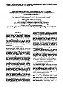
Fig. 8. Distribution of lightpath lengths relative to shortest-path route.
channel capacity over the minimum number of fiber links. RWA algorithms for lightpath establishment attempt to ensure this property. Since LONCA is a heuristic-based randomized algorithm operating over a set of lightpaths instead of a single lightpath, the algorithm does not specifically ensure this property. We analyzed the obtained lightpaths however, in order to calculate the lengths (in terms of fiber links traversed) of these lightpaths in relation to their shortest-hopdistance length. On average, 70% of the lightpaths established in the network were found to follow shortest path routing, and approximately 95% of the lightpaths could be established using less than four extra fiber links relative to their shortest path distances. There may exist, however, an occasional convoluted lightpath which may traverse a large number of fiber links. Fig. 8 shows the distribution of lightpath lengths relative to their shortest path lengths for ten random network topologies, each with 50 nodes. Similar results were obtained for networks of larger sizes; to conserve space they are not shown here. Although we expected the plots in Fig. 8 to be monotonically decreasing functions, the results appear to be otherwise. At this point, we do not have a clear explanation for this phenomenon. VI. CONCLUSION We explored an architecture for the design of passive optical wavelength-routed networks employing WGR’s as network routing elements. The architecture is highly fault-tolerant with switching functionality relegated to the periphery of the net-
work. Moreover, the architecture was shown to scale well with the number of nodes in the network. The periodicity property of the WGR also ensures that the network is upgradable to accommodate an increasing number of wavelengths. There are a number of open problems that need to be studied further for this architecture. The use of wavelength conversion at routing nodes in the network is expected to reduce the complexity of lightpath establishment in the network, but it may also reduce the fault-tolerance gained from the complete passivity of this architecture. Moreover, studies of heterogeneous architectures employing both WGR’s and WRS’s may lead to architectures which are more robust as well as flexible, i.e., they will allow routing decisions for the establishment of a lightpath to be made independent of other lightpaths. To summarize, we believe that the use of WGR’s in the design of an optical network opens up rich possibilities that need to be further explored. REFERENCES [1] A. Aggrawal, A. Bar-Noy, D. Coppersmith, R. Ramaswami, S. Schieber, and M. Sudan, “Efficient routing and scheduling algorithms for optical networks,” in Proc. 5th Ann. ACM-SIAM Symp. Discrete Algorithms, city, state, 1994, pp. 412–423. [2] S. B. Alexander, et al., “A precompetitive consortium on wide-band all-optical networks,” J. Lightwave Technol., vol. 11, pp. 714–735, May/June 1993. [3] K. Bala and C. Brackett, “Cycles in wavelength routed optical networks,” in LEOS ’94, Summer Topicals Meeting Dig. Optical Networks and Their Enabling Technologies, Lake Tahoe, NV, July 1994, pp. 7–8.
1050
IEEE JOURNAL ON SELECTED AREAS IN COMMUNICATIONS, VOL. 16, NO. 7, SEPTEMBER 1998
[4] D. Banerjee and B. Mukherjee, “Practical approaches for routing and wavelength assignment in large all-optical wavelength-routed networks,” IEEE J. Select. Areas Commun., vol. 14, pp. 903–908, June 1996. [5] R. A. Barry and P. A. Humblet, “Latin routers, design, and implementation,” J. Lightwave Technol., vol. 11, pp. 891–899, May/June 1993. [6] R. A. Barry and P. A. Humblet, “On the number of wavelengths and switches in all-optical networks,” IEEE/ACM Trans. Commun., vol. 42, pp. 583–591, Feb./Mar./Apr. 1994. [7] C. A. Brackett et al., “A scalable multiwavelength multihop optical network: A proposal for research on all-optical networks,” J. Lightwave Technol., vol. 11, pp. 736–753, May/June 1993. [8] C. Chen and S. Banerjee, “Optical switch configuration and lightpath assignment in wavelength routing multihop lightwave networks,” in Proc. IEEE INFOCOM ’95, Boston, MA, June 1995, pp. 1300–1307. [9] I. Chlamtac, A. Ganz, and G. Karmi, “Lightpath communications: An approach to high bandwidth optical WAN’s,” IEEE Trans. Commun., vol. 40, pp. 1171–1182, July 1992. , “Lightnets: Topologies for high speed optical networks,” J. [10] Lightwave Technol., vol. 11, pp. 951–961, May/June 1993. [11] C. Dragone, C. A. Edwards, and R. C. Kistler, “Integrated optics multiplexer on silicon,” IEEE Photon. Technol. Lett., vol. 3, pp. 896–898, Oct. 1991. [12] N. J. Frigo, P. P. Iannone, P. D. Magill, T. E. Darcie, M. M. Downs, B. N. Desai, U. Koren, T. L. Koch, C. Dragone, H. M. Presby, and G. E. Bodeep, “A wavelength division multiplexed passive optical network with cost-shared components,” IEEE Photon. Technol. Lett., vol. 6, pp. 1265–1367, 1994. [13] B. Glance, “Tunable optical add/drop filter,” in Tech. Dig. Optical Fiber Communications Conf. (OFC’95), vol. 8. San Diego, CA, Mar. 1995, pp. 85–87. [14] G. Hill, et al., “A transport network layer based on optical network elements,” J. Lightwave Technol., vol. 11, pp. 667–679, May/June 1993. [15] P. P. Iannone, N. J. Frigo, and T. E. Darcie, “A WDM PON architecture with bidirectional optical spectral splicing,” in Tech. Dig. Optical Fiber Communications Conf. (OFC’95), vol. 8. San Diego, CA, Feb. 1995, pp. 51–53. [16] K. C. Lee and V. O. K. Li, “A wavelength convertible optical network,” J. Lightwave Technol., vol. 11, pp. 962–970, May/June 1993. [17] I. P. Kaminow et al., “A wideband all-optical WDM network,” IEEE J. Select. Areas Commun., vol. 14, pp. 780–799, June 1996. [18] S. Minton, M. Johnston, A. Phillips, and P. Laird, “Minimizing conflicts: A heuristic repair method for constraint satisfaction and scheduling problems,” Artif. Intell., vol. 58, nos. 1–3, pp. 161–205, Dec. 1992. [19] B. Mukherjee, S. Ramamurthy, D. Banerjee, and A. Mukherjee, “Some principles for designing a wide-area optical network,” in Proc., IEEE INFOCOM ’94, Toronto, Canada, June 1994, pp. 110–119 (also, expanded version submitted for publication to IEEE/ACM Trans. Networking). [20] OFC’96 Tech. Dig., Feb. 1996, San Jose, CA. [21] R. Ramaswami and K. Sivarajan, “Optimal routing and wavelength assignment in all-optical networks,” IEEE/ACM Trans. Networking, vol. 3, pp. 489–500, Oct. 1995. [22] B. Selman, H. Levesque, and D. Mitchell, “A new method for solving hard satisfiability problems,” in Proc. 10th Nat. Conf. on Artificial Intelligence AAAI-92, San Jose, CA, July 1992, pp. 440–446. [23] M. G. Young, U. Koren, and B. I. Miller et al., “A 16 1 wavelength division multiplexer with integrated distributed Bragg reflector lasers and electroabsorption modulators,” IEEE Photon. Technol. Lett., vol. 5, pp. 908–910, Aug. 1993.
N 2N
2
[24] Z. Zhang and A. Acampora, “A heuristic wavelength assignment algorithm for multihop WDM networks with wavelength routing and wavelength reuse,” IEEE/ACM Trans. Networking, vol. 3, pp. 281–288, June 1995. [25] M. Zirngibl, C. H. Joyner, L. W. Stulz, C. Dragone, H. M. Presby, and I. P. Kaminow, “LAR-Net, a local access router network,” IEEE Photon. Technol. Lett., vol. 6, pp. 215–217, 1995.
Dhritiman Banerjee (S’90) received the B.Tech. (Hons.) degree from the Indian Institute of Technology, Madras, India, in 1988, and the M.S. and Ph.D. degrees from the University of California, Davis, in 1992. He is currently a Research Engineer at Hewlett Packard, Roseville, CA, working on high-speed gigabit networks. His research interests include architectures and protocols for WDM wide-area optical networks.
Jeremy Frank received the Ph.D. degree in computer science from the University of California, Davis, in 1998, and the B.A. degree in mathematics from Pomona College, Claremont, CA, in 1990. His thesis work involved solving combinatorial satisfiability and optimization problems using stochastic search methods. He is with the NASA Ames Research Center applying machine learning techniques to distributed optimization problems.
Biswanath Mukherjee (S’82–M’87) received the B.Tech. (Hons.) degree from the Indian Institute of Technology, Kharagpur, India, in 1980, and the Ph.D. degree from the University of Washington, Seattle, in June 1987. At the University of Washington, he held a GTE Teaching Fellowship and a General Electric Foundation Fellowship. In July 1987, he joined the University of California, Davis, where he has been a Professor of Computer Science since July 1995, and Chairman of Computer Science since September 1997. He is author of the textbook Optical Communication Networks (New York: McGraw-Hill, 1997), a book which received the Association of American Publishers, Inc.’s 1997 Honorable Mention in Computer Science. His research interests include lightwave networks, network security, and wireless networks. Dr. Mukherjee is co-winner of paper awards presented at the 1991 and the 1994 National Computer Security Conferences. He serves on the editorial boards of the IEEE/ACM TRANSACTIONS ON NETWORKING, IEEE NETWORK, ACM/Baltzer Wireless Information Networks (WINET), Journal of High-Speed Networks, and Photonic Network Communications. He served as the Technical Program Chair of the IEEE INFOCOM’96 Conference.