tion method inspired by the work of Chris Nielsen in [10]. As in [4], we rely on an input dynamic extension to design a path following controller. Besides solving ...
Path Following Controller for a Quadrotor Helicopter Ashton Roza, Manfredi Maggiore
Abstract— A path following controller is presented for a quadrotor helicopter model. The controller relies on input dynamic extension and feedback linearization. The controller allows the designer to specify the speed profile of the quadrotor on the path and its yaw angle as a function of the displacement.
I. I NTRODUCTION Applications for search and rescue, exploration, security and inspection are often dangerous or time consuming for a human operator to perform. One solution is to have a model sized quadrotor helicopter do the task. That is, command a quadrotor to follow a predefined path while meeting additional specifications regarding its motion such as speed or orientation. For instance, the quadrotor may orient itself to point an on-board camera or tool in a desired direction as a function of displacement along the path. Two methods to accomplish this are trajectory tracking and path following while secondary problems may deal with disturbance rejection (e.g., wind in outdoor environments), unmodelled dynamics (e.g., aerodynamic effects) and parameter uncertainties. In the trajectory tracking case, the quadrotor tracks a time parameterized reference signal that moves along the path while simultaneously specifying yaw angle. The majority of the literature for quadrotor trajectory tracking uses a hierarchical method called backstepping. For instance, in [1] and [2], the controller is split into an outer translational control loop and an inner rotational control loop. In the outer loop, the reference signal is the desired displacement along the path and the control input is the thrust. There are also additional virtual inputs that together with the desired yaw angle, become the reference signals for the inner rotational loop. In this inner loop, the remaining control inputs representing body torques are assigned. In [1] a model predictive controller is used for the translational subsystem whereas a robust nonlinear H∞ controller is used for the rotational subsystem. In [2] a sliding-mode controller is used for both subsystems where neural networks are used for disturbance rejection. In [3], the approach has three control steps. The first step uses the thrust input and yawing torque to control the quadrotor height and yaw angle respectively. In the second step, the pitching torque is used to control y-position and pitch angle. In this step, a nested saturation control is used to bound the pitching torque. The third step is similar to the second, where the rolling torque is used to control x-position and roll angle. In [4], the authors use a feedback linearization approach where the path and yaw specifications are described through the system outputs and disturbance rejection is provided through an adaptive estimator. Other relevant work regarding quadrotor control
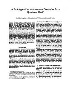
can be found in [5] and [6] which both present attitude, position and trajectory tracking controllers implemented on a testbed to obtain experimental results. Quaternion-based attitude control is presented in [7] while quadrotor maneuvers are explored in [8] and [9]. Specifically, [8] has a quadrotor fly through openings and perch on angled surfaces while [9] presents a learning strategy for flips. The main issue with the trajectory tracking method is that if the quadrotor loses track of the reference signal, it may leave the path and collide with off-course objects. For this reason, we will focus on the path following approach. The goal of the path following approach is to stabilize a set of permitted trajectories where the quadrotor is on the path and meets additional specifications regarding its speed and orientation as a function of its displacement. The advantage of the path following method comes from its invariance properties where if the quadrotor begins on a permitted trajectory, it will remain on it for all time. However, even if the quadrotor is not exactly on a permitted trajectory or has been perturbed slightly off of one, it will at least converge towards nearby points on the path rather than chasing a distant reference signal. This contrasts the trajectory tracking approach where this invariance property does not hold. The development in this paper uses a feedback linearization method inspired by the work of Chris Nielsen in [10]. As in [4], we rely on an input dynamic extension to design a path following controller. Besides solving the path following problem, our control design allows one to specify the speed profile and yaw angle of the quadrotor along the path. Notation. Throughout the paper, we will use the shorthand cθ := cos θ, sθ := sin θ, tθ := tan θ, seθ := sec θ. By dfx we will denote the Jacobian of a function f at x. If f is a realvalued function, the gradient of f with respect to the vector x = col (x1 . . . xn ) will be denoted by ∂(x1 ,...,xn ) f , or more concisely ∂x f . Note that ∂x f = dfx ⊤ for a real-valued f . Finally, v · w denotes the Euclidean inner product between vectors v and w ∈ R3 . II. BACKGROUND The quadrotor model developed in this section is standard. For instance, see Mokhtari, Benallegue, and Orlov in [4]. A quadrotor helicopter consists of four rotors connected to a rigid frame, as shown in Figure 1. Denote the inertial frame by I, the body frame attached to the quadrotor centre of mass by B and the distance from the centre of mass to the rotors by d. Corresponding to each rotor is a thrust force fi acting along the zb axis and a reaction torque τri that opposes the direction of rotation. To produce a thrust fi in the negative zb (i.e., upward) direction, the rotors on the xb
P where Fext is the sum of external forces composed of a gravity force and thrust force, m is the� quadrotor �T mass, g is the acceleration due to gravity, e3 = 0 0 1 and R is the rotation matrix from B to I given by, cθ cψ cψ sθ sφ − cφ sψ cφ cψ sθ + sφ sψ R = cθ sψ sθ sφ sψ + cφ cψ cφ sθ sψ − cψ sφ . −sθ cθ sφ cθ cφ Fig. 1: Quadrotor system.
axis rotate in the clockwise direction and the rotors on the yb axis rotate in the counter-clockwise direction. The control inputs to the system are u1 , u2 , u3 , u4 where u1 is the total thrust along the zb axis and u2 , u3 , u4 are the torques about the xb , yb , zb axes respectively. The physical inputs are the motor torques applied to the rotors denoted by τ1 , τ2 , τ3 , and τ4 . Using the development from Castillo, Lozano, and Dzul in [3], the rotor dynamics are given by Irz Ω˙ ri = −bΩ2ri +τi where Irz is the rotor moment of inertia about the rotor z-axis, Ωri is the angular speed of rotor i and b is a coefficient of friction due to aerodynamic drag on the rotor. There is also an algebraic relationship between the rotor thrust and rotor speed given by, fi = γΩ2ri where γ is a parameter that can be experimentally measured. If we assume steady-state rotor dynamics such that Ω˙ ri = 0 then fi = (γ/b)τi = cτi where c = γ/b is the algebraic scaling factor between the rotor thrust and the applied motor torque. Using this fact, it is readily seen that the relationship between the control inputs and the motor torques is given by τ1 c c c c u1 u2 0 −cd τ2 0 cd = M τ. u= u3 = cd 0 − cd 0 τ3 u4 1 −1 1 −1 τ4 In the above, the total thrust is equal to the summation of the four rotor thrusts; the torque about the xb axis is proportional to the differential thrust of the two rotors on the yb axis, f4 −f2 ; the torque about the yb axis is proportional to the differential thrust of the two rotors on the xb axis, f1 −f3 ; and the torque about the zb axis is equal to the summation of the four reaction torques τri which are equal and opposite to the applied motor torques τi . Therefore given u, one can determine the required motor torques by τ = M −1 u. Let the states of the quadrotor system be given by, X = col (x, y, z): position in I Φ = col (ψ, θ, φ): orientation (yaw, pitch, and roll) V = col (u, v, w): velocity in I ω = col (p, q, r): angular velocity in B. We now model the system dynamics neglecting gyroscopic effects and disturbances. Using Newton’s equation, the translational dynamics of the quadrotor system are given by, X˙ = V X mV˙ = Fext = mge3 − u1 Re3
(1)
Using Newton-Euler’s equation, the rotational dynamics of the quadrotor system are given by, 0 sφ seθ cφ seθ cφ −sφ ω Φ˙ = 0 (2) 1 s φ tθ c φ tθ X � �T J ω˙ + ω × Jω = Text = u2 u3 u4 P where Text is the vector of external torques in B and J is the symmetric inertia matrix in B with diagonal elements Ix , Iy and Iz . The state vector is taken as χ = col (X, Φ, V, ω) ∈ X := R12 and the system model can be represented in the control-affine form, χ˙ = f (χ) + g (χ) u, y = h(χ) with the definitions of f, g derived from equations (1) and (2). III. P ROBLEM S TATEMENT The objective of the path following problem is to control the quadrotor helicopter to follow a predefined path in R3 while attaining a desired velocity and yaw angle as it travels along this path. This is stated more precisely below. Path Following Problem (PFP): Consider the system given by equations (1) and (2). Given a Jordan curve C in R3 , find a continuous feedback u = col (u1 , . . . , u4 ) such that under appropriate initial conditions, the closed-loop system meets the following goals: G1 The quadrotor asymptotically converges to C G2 The velocity asymptotically converges to a specified value dependent on the quadrotor displacement along C G3 The yaw angle asymptotically converges to a specified value dependent on the quadrotor displacement along C. The path, velocity and yaw specifications are formulated in terms of system outputs that we would like to asymptotically zero out. Definition 3.1: A path specification is a smooth function col (h1 (X), h2 (X)), R3 → R2 , such that the path C = {X : h1 (X) = h2 (X) = 0} is a Jordan curve in R3 and ∂X h1 , ∂X h2 are linearly independent on C (i.e., zero is a regular value of col (h1 , h2 )). The enforcement of the path specification meets goal G1 in PFP. Next, we would like to define velocity and yaw specifications. Definition 3.2: A velocity specification is a smooth function X → R defined as h3 (χ) = (∂X h1 × ∂X h2 ) / k∂X h1 × ∂X h2 k · V − α(X) where
the smooth function α(X) 6= 0 specifies the velocity along C. For each point X ∈ C and each velocity vector V ∈ R3 , the vector (∂X h1 × ∂X h2 ) / k∂X h1 × ∂X h2 k · V represents the component of V tangent to the path C at X. Thus, h3 (χ) expresses the requirement that when X ∈ C the component of the quadrotor’s velocity tangential to C be equal to a desired value given by α(X). The magnitude of α(X) is the desired speed, and its sign indicates the desired direction of travel along C (clockwise or counter-clockwise). Hence, the enforcement of the velocity specification meets goal G2 in PFP. Definition 3.3: A yaw specification is a smooth function X → R defined as h4 (χ) = ψ − β(X). In the above, the desired yaw angle at a point X along C is given by β(X). The enforcement of the yaw specification meets goal G3 in PFP. Let s := col(s1 , . . . , s4 ) and define π : X → R3 as π(X, Φ, V, ω) = X. Defining the output function h : X → R4 as h1 (π(χ)) h2 (π(χ)) (3) s = h(χ) := ∂ h ×∂ h X 1 X 2 k∂ h ×∂ h k · V − α(X) , X
1
X
2
ψ − β(X)
the objective of PFP can be restated as that of designing a feedback such that, for a suitable set of initial conditions, h(χ(t)) → 0 along solutions of the closed-loop system. In other words, we want the set Γ = h−1 (0) to be attractive for the closed-loop system. Attractivity alone, however, is not desirable in path following applications because any slight perturbation of the quadrotor off of Γ may result in system behaviour where the quadrotor initially diverges significantly from the path before converging back to it. Rather, we would like Γ to be asymptotically stable. This, however, is not possible since Γ is not controlled invariant, i.e., it cannot be made invariant by any choice of feedback. To illustrate, if the system is initialized on Γ but the velocity vector V (0) is not tangent to C, the quadrotor will leave C, and hence Γ, no matter what feedback we choose. In light of this observation, we will stabilize the maximal controlled invariant subset of Γ which we call the path following manifold introduced in [10]. The path following manifold is simply the zero dynamics manifold of system (1), (2) with output (3), and it will be characterized in the next section. IV. S OLUTION OF PFP The simplest way to stabilize the zero dynamics of a nonlinear control system is to use, when feasible, input-output feedback linearization [11]. In the context of PFP, in order to apply this technique we need to find conditions under which the output h(χ) in (3) yields a well-defined vector relative degree. We begin by finding conditions under which a vector relative degree is well-defined. Then, we design a controller based on input-output feedback linearization, and we prove that it solves PFP.
A. Investigation of vector relative degree conditions Taking time derivatives of the four outputs in (3) along the vector fields of the control system (1)-(2), one can check that the control inputs first appear in d2 s1 /dt2 , d2 s2 /dt2 , ds3 /dt, and d2 s4 /dt2 suggesting that if vector relative degree were well-defined it would be given by {2, 2, 1, 2}. However, one can check that the corresponding decoupling matrix D has the form ⋆ 0 0 0 ⋆ 0 0 0 D= ⋆ 0 0 0 , ⋆ 0 ⋆ ⋆ so that D is always singular, implying that the vector relative degree {2, 2, 1, 2} is not well-defined anywhere. Interestingly, the same problem arises when one wants to address the tracking problem, a fact pointed out in [4], although in this case the output function is completely different. Here, as in [4], we achieve a well-defined vector relative degree through the technique of input dynamic extension [11]. Specifically, we add two integrators at the thrust input u1 , while leaving the remaining inputs unchanged. That is, we let u1 = ζ, ζ¨ = u ¯ 1 , u2 = u ¯ 2 , u3 = u ¯ 3 , u4 = u ¯4
(4)
where u ¯1 , u ¯2 , u ¯3 , u ¯4 are the new control inputs. The quadrotor model with dynamic compensation is given by equations (1), (2), � and (4) with the � augmented state vector defined ˙ as χ ¯ = col X, Φ, V, ω, ζ, ζ ∈ X¯ := X × R2 . The system model can be represented in the control-affine form, ¯ χ), χ ¯˙ = f¯ (χ) ¯ + g¯ (χ) ¯ u ¯, y¯ = h( ¯ with the definitions of f¯, g¯ derived from equations (1), (2), and (4). Letting π ¯ : X¯ → X be the projection ˙ 7→ (X, Φ, V, ω), the new output function (X, Φ, V, ω, ζ, ζ) ¯ : X¯ → R4 is simply given by h ¯ χ) h( ¯ =h◦π ¯ (χ), ¯
(5)
with h given in (3). To solve PFP for the augmented system, we want to stabi¯ −1 (0). ¯=h lize the maximal controlled invariant subset of Γ The following lemma outlines the conditions under which the vector relative degree is well-defined for the augmented system. Lemma 4.1: The augmented quadrotor system given by equations (1), (2) and (4) with output (5) has a well-defined vector relative degree {r1 , r2 , r3 , r4 } := {4, 4, 3, 2} at a point ˙ if and only if ζ 6= 0 and φ 6= χ ¯ = (X, (ψ, θ, φ), V, ω, ζ, ζ) π ±2. Proof: The determinant of the decoupling matrix D of the augmented system is given by det(D) = −
d3 ζ 2 (∂ψ h4 ) cφ (∂X h1 × ∂X h2 ) · ∂V h3 . m3 I x I y I z c θ
It follows from the definitions of h1 , h2 , h3 that ∂X h1 , ∂X h2 and ∂V h3 form a linearly independent set. This is because ∂X h1 and ∂X h2 are linearly independent, k∂V h3 k = 1 6= 0,
and ∂V h3 = (∂X h1 × ∂X h2 ) / k∂X h1 × ∂X h2 k is perpendicular to ∂X h1 and ∂X h2 . It follows from the definition of h4 that ∂ψ h4 = 1 6= 0. Therefore det(D) 6= 0 if and only if ζ 6= 0 and φ 6= ± π2 . It follows that the system has well-defined vector relative degree at any point χ ¯ where the conditions ζ 6= 0 and φ 6= ± π2 are satisfied because the decoupling matrix D has full ¯ i = 0 for i, j ∈ {1, . . . , 4}, k ∈ {0, . . . , ri − rank and Lg¯j Lkf¯h 2}. Note also that, in addition to the conditions of the lemma above, we must impose θ 6= ± π2 as this presents a singularity in the model inherited by the singularity in the Euler angle representation. Consider the set given by ¯ i = 0, j = 0, . . . , ri − 1, i = 1, . . . , 4}, (6) ¯ ⋆ = {χ Γ ¯ : Ljf¯h where {r1 , r2 , r3 , r4 } := {4, 4, 3, 2}. If the augmented quadrotor system has a well-defined vector relative degree ¯ ⋆ , then it follows that Γ ¯⋆ {4, 4, 3, 2} at each point χ ¯ ∈ Γ ¯ is the maximal controlled invariant subset of Γ, which is precisely the set we wish to stabilize. In light of Lemma 4.1, ¯⋆ in order to have a well-defined vector relative degree on Γ ⋆ ¯ we need to determine whether, on Γ , ζ 6= 0, φ 6= ±π/2, and θ 6= ±π/2. This is the subject of the next proposition. Proposition 4.2: For the augmented quadrotor system given by equations (1), (2), and (4), with output (5), there exists K ⋆ > 0 such that for all K ∈ (0, K ⋆ ), if the velocity specification is chosen so that max X∈C |α(X)| ≤ K and max X∈C kdαX (X)k ≤ K the system has a well-defined ¯⋆. vector relative degree {r1 , r2 , r3 , r4 } = {4, 4, 3, 2} on Γ Proof: Let K1 = maxX∈C |α(X)| and K2 = maxX∈C kdαX (X)k. The constants K1 and K2 exist and are finite because α is smooth and C is compact. From Lemma 4.1, the system has well-defined vector relative degree and no Euler angle singularities are encountered on ¯ ⋆ if and only if, Γ ¯⋆. (i) ζ is bounded away from 0 on Γ ¯⋆. (ii) φ, θ are bounded away from ± π2 on Γ ⋆ ¯ 1 (χ) ¯ 2 (χ) ¯ we have h By definition, on Γ ¯ = h ¯ = 0 ¯ 1 (χ) ¯ 2 (χ) and Lf¯h ¯ = Lf¯h ¯ = 0 or, recalling that χ ¯ = ˙ (X, Φ, V, ω, ζ, ζ), h1 (X) = h2 (X) = 0 and ∂X h1 (X) · V = ¯⋆, ∂X h2 (X)·V = 0. The latter two identities imply that, on Γ V is orthogonal to the vectors ∂X h1 (X) and ∂X h2 (X). We ¯ 3 (χ) also have h ¯ = 0, or (∂X h1 × ∂X h2 )/ k∂X h1 × ∂X h2 k · V = α(X). Since V is orthogonal to both ∂X h1 and ∂X h2 , ¯⋆, the above identity implies that on Γ
from which we have that |ζ| ≥ m (g − K1 (K1 C + K2 )), and thus for all K1 (K1 C + K2 ) < g, |ζ| > 0, implying that property (i) above is satisfied. We also have that |ζ| ≤ m (g + K1 (K1 C + K2 )). In other words, ζ is bounded from ¯ ⋆ . Using the fact that |w| above on Γ ˙ = |g − ζ/m(cθ cφ )| ≤ ˙ kV k ≤ K1 (K1 C + K2 ), we have |cθ cφ | ≥
g − K1 (K1 C + K2 ) g − K1 (K1 C + K2 ) = . ζ g + K1 (K1 C + K2 ) max m
It thus follows that if K1 (K1 C + K2 ) < g, |cθ cφ | > 0, and ¯ ⋆ , implying thus θ and φ are bounded away from ± π2 on Γ ⋆ that p property (ii) above holds. In⋆ conclusion, setting K = g/(1 + C), for all K ∈ (0, K ) the augmented quadrotor ¯⋆. system has a well-defined vector relative degree on Γ Proposition 4.2 states that if the velocity specification is chosen so that the desired tangential velocity α(X) and dαX (X) have a sufficiently small upper bound K, then the augmented quadrotor system has a well-defined vector ¯ ⋆ , and therefore this set is the path relative degree on Γ following manifold we wish to stabilize to solve PFP. The path following manifold is one-dimensional since n − (r1 + r2 + r3 + r4 ) = 14 − (4 + 4 + 3 + 2) = 1 where n = 14 is the number of states for the augmented system. Remark 4.3: Recall the function V = µ(X)α(X) in (7) which expresses the velocity of the quadrotor in terms of ¯ ⋆ , and its time derivative its displacement� X when χ ¯ ∈ Γ 2 ˙ V = dµX µα + µdαX (µα). If one computes K1 (K1 C + K2 ) := maxX∈C kV˙ k, then the proof of Proposition 4.2 provides the upper bounds K1 and K2 satisfying K1 (K1 C + K2 ) < g. Since C is a closed curve, the computation of C, and hence of K1 and K2 , can be easily carried out numerically. B. Controller Design From now on we will assume that the velocity specification has been chosen so that maxX∈C |α(X)| < K ⋆ and maxX∈C kdαX (X)k < K ⋆ . The design of an inputoutput feedback linearization controller h iT is standard. Let r1 ¯ r4 ¯ ¯ . . . Lf¯ h4 (χ) ¯ b(χ) ¯ := Lf¯ h1 (χ) and define the feedback transformation u ¯ = D−1 (χ) ¯ (−b(χ) ¯ + v) ,
(8)
where v = col (v1 , . . . , v4 ) is the new control input, and where D(χ) ¯ is the decoupling matrix with entries ¯ i , i, j ∈ {1, . . . , 4}. Let ξ i = Dij = Lg¯j Lrf¯i −1 h h iT ¯ i (χ) ¯ i (χ) h ¯ . . . Lrf¯i −1 h ¯ , i = 1, . . . , 4, and choose vi as (9) vi = −kri −1 ξri i − · · · − k0 ξ1i , i = 1, . . . , 4
∂ X h1 × ∂ X h2 . (7) k∂X h1 × ∂X h2 k � In particular, V˙ = µα ˙ + µα˙ = dµX µα2 + µdαX (µα) where kµk ≤ 1 and therefore, kV˙ k ≤ kdµX kK12 + K1 K2 . such that sr + kri −1 sri −1 + · · · + k0 has roots in the open Since dµX is continuous and X ∈ C, a compact set, it left-half plane. The resulting control system is illustrated in ¯ ⋆ , kV˙ k ≤ K1 (K1 C+K2 ), for some C > 0. Figure 2. Now the problem is whether the controller just follows that, on Γ ⋆ ¯ ¯⋆. On Γ we have designed indeed stabilizes the path following manifold Γ
1 In view of the fact that
0 − m (cφ cψ sθ + sφ sψ )
� � � � 0 + ζ − 1 (cφ sθ sψ + cψ sφ ) ≤ K1 (K1 C+K2 ) 0ri −1×1 0 Iri −1 i kV˙ k = i m ˙
vi , (10) ξ + ξ =
g − 1 (cθ cφ ) 1 0 01×ri−1 V = µ(X)α(X), µ(X) :=
m
Fig. 2: Control system block diagram.
The input-output linearizing feedback guarantees that solutions of the closed-loop system originating in a neighbour¯ ⋆ are such that ξ i (χ(t)) hood of Γ ¯ → 0, i = 1, . . . , 4, provided that there are no finite escape times. Besides having to show that the closed-loop system has no finite escape ¯ ⋆ , there is another issue that times in a neighbourhood of Γ ¯ ⋆ = {χ requires some analysis. Although Γ ¯ : ξ i (χ) ¯ = 0, i = 1, . . . , 4}, the fact that ξ i (χ(t)) ¯ → 0, i = 1, . . . , 4, does not ¯ ⋆ . To illustrate, consider the imply, in general, that χ(t) ¯ →Γ 2 function ξ(χ) ¯ = χ/(1 ¯ +χ ¯ ), and suppose that χ(t) ¯ = t. Then, ξ(χ) ¯ → 0 but χ(t) ¯ does not tend to {χ ¯ : ξ(χ) ¯ = 0}. In order to address the two issues described above we ¯⋆ define a diffeomorphism valid in a neighbourhood of Γ which maps the system into a standard normal form. In order to do that, we need some preliminary definitions. Let L denote the length of the curve C, and denote by S 1 the set of real numbers modulo L (this set is diffeomorphic to the unit circle). Fix a point o on C, and define the map Λ : C → S 1 as X 7→ η, where η is the arc length of the portion of C from o to X found moving in the counterclockwise direction. Since C is a Jordan curve, the function Λ is a diffeomorphism C → S 1 . Let p(X) be the function mapping a point X ∈ R3 to the closest point on C. Note that p|C is the identity map. On some neighbourhood U of C the function p : U → C is well-defined and smooth. Finally, recall the definition of π ¯ and π χ ¯ ∈ X¯
π ¯
χ∈X
π
X ∈ R3
and define a function λ(χ) ¯ as λ(χ) ¯ := Λ ◦ p ◦ π ◦ π ¯ (χ). ¯ By construction, λ is a smooth function in a neighbourhood of ¯ 1 (χ) ¯ 2 (χ) ¯⋆. {h ¯ =h ¯ = 0}, and hence in a neighbourhood of Γ Now define the coordinate transformation h iT h iT .. .. 1 4 = σ( χ) ¯ := (11) ξ . η ξ (χ) ¯ . . . ξ (χ) ¯ . λ(χ) ¯ Lemma 4.4: Under the conditions of Proposition 4.2, the function σ(χ) ¯ : X¯ → R13 × S 1 is a diffeomorphism of a ¯ ⋆ onto its image, and Γ ¯ ⋆ is diffeomorphic neighbourhood of Γ 1 to S . Proof: According to the generalized inverse function theorem in [12], we must show that, ¯ ⋆ , dσχ¯ is an isomorphism (i) for all χ ¯∈Γ ⋆ ¯ → S 1 is a diffeomorphism. (ii) σ|Γ¯ ⋆ : Γ ¯ ⋆ , dσχ¯ has determinant, For each χ ¯∈Γ det(dσχ¯ ) = −
¯ 4 )2 c 2 � � � ζ 4 (∂ψ h φ ¯3 3 ¯ 2 · ∂χ¯ h ¯ 1 × ∂χ¯ h ∂χ¯ h 6 m cθ � � � ¯ 1 × ∂χ¯ h ¯ 2 · ∂χ¯ λ . · ∂χ¯ h
Under the conditions of proposition 4.2, ζ 6= 0 and θ, φ 6= ¯ ⋆ . Therefore, det(dσχ¯ ) 6= 0 if and only if ∂χ¯ λ is ± π2 on Γ
¯ 2 or, what is the ¯ 1 and ∂χ¯ h linearly independent from ∂χ¯ h same, if {∂X h1 , ∂X h2 , ∂X Λ} is a linearly independent set, ¯⋆ where X = π ◦ π ¯ (χ). ¯ That this is indeed the case on Γ follows from the fact that Λ is the displacement along C and hence, ∂X λ is tangent to C and perpendicular to ∂X h1 and ¯ ⋆ , σ|Γ¯ ⋆ = ∂X h2 . To show (ii) consider the restriction of σ to Γ col(0, . . . , 0, λ|Γ¯ ⋆ ). The map λ|Γ¯ ⋆ is smooth and surjective because it is the composition of four smooth surjective maps, π ¯ : X¯ → X , π : X → R3 , p : R3 → C, and Λ : C → S 1 . Therefore σ|Γ¯ ⋆ is also smooth and surjective. Since Λ : C → S 1 is a diffeomorphism, proving injectivity of σ|Γ¯ ⋆ is ¯ ⋆ → C. equivalent to proving injectivity of (p ◦ π ◦ π ¯ )|Γ¯ ⋆ : Γ Thus, we must show that given a point X ∈ C, we can ¯ ⋆ uniquely such that p ◦ π ◦ π construct χ ¯∈Γ ¯ (χ) ¯ = X. Since ⋆ ¯ i (χ) ¯ on Γ we have h ¯ = 0, i = 1, . . . , 4, given a point X ∈ C we know that V = µ(X)α(X), where µ was � defined in (7), and ψ = β(X). Moreover, V˙ = dµX µα2 + µdαX (µα). From the identity − ζ/m(cφ cψ sθ + sφ sψ ) u˙ V˙ = v˙ = − ζ/m(cφ sψ sθ − sφ cψ ) , g − ζ/m(cθ cφ ) w˙ � � letting a(X) = −m V˙ − col(0, 0, g) , we can express ζ, θ, φ as smooth functions of X with ζ = ka(X)k, φ = sin−1 (sψ a1 (X) − cψ a2 (X)) and θ = sin−1 (cψ a1 (X) + sψ a2 (X)/cφ ) where ζ > 0, − π2 ≤ φ, θ ≤ π 2 hold from Proposition 4.2. Hence, ζ, φ, θ are specified through smooth functions of X. Also, ζ˙ = dζX V = dζX µ(X)α(X). Finally, we observe the relationship between Φ and ω given by, 0 sφ seθ cφ seθ cφ −sφ ω = Y ω Φ˙ = 0 1 s φ tθ c φ tθ ˙ = Y −1 dΦX µ(X)α(X). This is a and hence, ω = Y −1 Φ smooth function of X because Y −1 , Φ, µ and α are smooth functions of X, proving that σ|Γ¯ ⋆ is injective and its inverse is smooth. The important feature of Lemma 4.4 is the fact that the map σ is proved to be a diffeomorphism in a neighbourhood of ¯ ⋆ , rather than just in a neighbourhood of a the entire set Γ point. We now present the main result of this paper. Theorem 4.5: For the augmented quadrotor system given by equations (1), (2), and (4), with output (5), and with the feedback (8)-(9) there exists K ⋆ > 0 such that for all K ∈ (0, K ⋆ ), if the velocity specification is chosen so that max X∈C |α(X)| ≤ K and max X∈C kdαX (X)k ≤ K the ¯ ⋆ in (6) is exponentially stable path following manifold Γ for the closed loop system, and hence PFP is solved in a ¯⋆. neighbourhood of Γ Proof: By Proposition 4.2, the feedback (8)-(9) is ¯ ⋆ . By Lemma 4.4 the well-defined in a neighbourhood of Γ function σ(χ) ¯ : X¯ → R13 × S 1 is a diffeomorphism of a ¯ ⋆ onto its image, and Γ ¯ ⋆ is diffeomorphic neighbourhood of Γ 1 ¯⋆ to S , and hence compact. In (ξ, η) coordinates, the set Γ ⋆ ¯ ) = {(ξ, η) : ξ = 0}. The ξ subsystem is given by σ(Γ
pitch roll yaw
50 0 0
20 40 time (s)
60
0
20 10 0
20 40 time (s)
20 18
0
20 40 time (s)
0 0 y−10 −10 x
60
22
60
300 200 100 0 −100
10
pitch roll yaw
0
5 10 time (s)
15
speed (m/s)
z 2
21
Thrust (zeta)
100
22
4
angle (degrees)
angle (degrees)
10
0 0 y −10 −10 x
speed (m/s)
21 20 10
Thrust (zeta)
z
22
20 10 0
0
5 10 time (s)
15
0
5 10 time (s)
15
50
0
Fig. 3: Case 1: simulation results for α = 3.
Fig. 4: Case 2: simulation results for α = 15.
in (10) is LTI and the feedback (8)-(9) makes it exponentially ¯ ⋆ or, what is the same, for stable. Thus, for all χ(0) ¯ near Γ all ξ(0) near 0, ξ(t) → 0 exponentially as long as there are no finite escape times. There cannot be finite escape times because ξ(t) is bounded and η(t) ∈ S 1 , a compact ¯ ⋆ ) is exponentially stable, which implies that set. Hence, σ(Γ ¯ ⋆ is exponentially stable as well. Γ
VI. C ONCLUSIONS
V. S IMULATION R ESULTS In this section, simulation results are presented for the quadrotor specified to travel at a constant speed along a circular path of radius r parallel to the x − y plane, at a height of z = 20m and yaw angle of 0◦ . That is, the ¯ = x2 + y 2 − r 2 , h ¯ 2 = z − 20, specifications p are given by h1p 2 2 2 2 ¯ ¯ 4 = ψ. h3 = uy/ (x + y ) − vx/ (x + y ) − α and h ˙ The initial conditions are taken as ζ = mg, ζ = 0, (x, y, z) = (0, 10, 20)m, (u, v, w) = (−1, 0, 0)m/s and (φ, θ, ψ) = ( π8 , π8 , π2 )rad. The parameters are chosen as in [4] to be m = 2Kg, Ix , Iy , Iz = 1.2416N · m/rad/s2 , d = 0.1m and g = 9.81m/s2 . On Γ⋆ , theprelationship V = µ(X)α(X) in (7) � �T is given by V = α/ x2 + y 2 y − x 0 . Therefore � �T and maxC kV˙ k = V˙ = α2 /(x2 + y 2 ) − x − y 0 2 α /r, which corresponds to the centripetal acceleration of the quadrotor moving around a circle at constant speed |α|. Following Remark 4.3, we must choose α so that α2 /r < g, √ or |α| < rg. Taking r = 10m, we must pick |α| < 9.9. Two simulation cases are considered where the quadrotor travels around the path with a constant speed of α = 3m/s and α = 15m/s respectively. Therefore, the first case meets the conditions above but the second does not. Figures 3 and 4 show simulation results for case 1 and case 2 respectively. In both cases, the quadrotor successfully converges to the path C. Also, the velocity and yaw angle converge to the desired values. One difference between the two cases are the roll and pitch angles. In the first case, the two angles have a maximum magnitude of 5.25◦ while for the second, the maximum magnitude is 66.45◦ . Another difference is an increased thrust input for the second case. In neither case does the quadrotor hit a point where φ, θ = ±π/2 or ζ = 0 and therefore, the controller is well-defined for the specific initial conditions we have considered. Note, however, that in case 2 there is no guarantee that for any initial ¯ ⋆ the solution does not cause singularities condition near Γ in the controller.
We have presented a basic path following controller which relies on input dynamic extension and feedback linearization to solve the path following problem for a quadrotor helicopter. Our controller allows the designer to specify a speed profile on the path and the yaw angle of the quadrotor as a function of its displacement along the path. In future research we will investigate the solution of the same problem without employing input dynamic extension, and we will address issues of robustness against unmodelled effects such as aerodynamic drag forces and parametric uncertainties. R EFERENCES [1] G. V. Raffo, M. Ortega, and F. Rubio, “An integral predicitive/nonlinear H∞ control structure for a quadrotor helicopter,” Automatica, vol. 46, pp. 29–39, 2010. [2] A. Das, F. Lewis, and K. Subbarao, “Backstepping approach for controlling a quadrotor using lagrange form dynamics,” Journal of Intelligent Robot Systems, vol. 56, pp. 127–151, 2009. [3] P. Castillo, R. Lozano, and A. Dzul, “Stabilization of a mini rotorcraft with four rotors,” IEEE Control Systems Magazine, pp. 45–55, 2005. [4] A. Mokhtari, A. Benallegue, and Y. Orlov, “Exact linearization and sliding mode observer for a quadrotor unmanned arial vehicle,” International Journal of Robotics and Automation, vol. 21, no. 1, pp. 39–49, 2006. [5] N. Michael, D. Mellinger, Q. Lindsey, and V. Kumar, “The grasp multiple micro-UAV testbed,” IEEE Robotics and Automation Magazine, vol. 17, pp. 56–65, 2010. [6] G. Hoffmann, H. Huang, S. Waslander, and C. Tomlin, “Precision flight control for a multi-vehicle quadrotor helicopter testbed,” Control Engineering Practice, vol. 19, pp. 1023–1036, 2011. [7] A. Tayebi and S. McGilvray, “Attitude stabilization of a VTOL quadrotor aircraft,” IEEE Transactions on Control Systems Technology, vol. 14, no. 3, pp. 562–566, 2006. [8] D. Mellinger, N. Michael, and V. Kumar, “Trajectory generation and control for precise aggressive maneuvers with quadrotors,” in Proceedings of the International Symposium on Experimental Robotics, 2010. [9] S. Lupashin, A. Sch¨ollig, M. Sherback, and R. D’Andrea, “A simple learning strategy for high-speed quadrocopter multi-flips,” in Proceedings of the 2010 IEEE International Conference on Robotics and Automation, May 3-8 2010, pp. 1642–1648. [10] C. Nielsen, “Set stabilization using transverse feedback linearization,” Ph.D. dissertation, University of Toronto, 2009. [11] A. Isidori, Nonlinear Control Systems, 3rd ed. Springer Verlag, 1995. [12] V. Guillemin and A. Pollack, Differential topology. New Jersey: Prentice Hall, 1974.