AbstractâPath planning is an important area in the control of autonomous mobile robots. Recent work has focused on aspects reductions in processing time ...
(IJACSA) International Journal of Advanced Computer Science and Applications, Vol. 5, No. 8, August 2014
Path Planning in a Dynamic Environment by the approach of the sliding on edge Mohamed EL KHAILI Laboratory SSDIA, ENSET, Mohammedia HASSAN II University, Casablanca, Morocco
Abstract—Path planning is an important area in the control of autonomous mobile robots. Recent work has focused on aspects reductions in processing time than the memory requirements. A dynamic environment uses a lot of memory and hence the processing time increases too. Our approach is to reduce the processing time by the use of a pictorial approach to reduce the number of data used. In this paper, we present a path planning approach that operates in three steps. First, a construction of the visibility tree is performed. The following treatments are not performed on the original image but on the result tree whose elements are specific points of the environment linked by the relationship of visibility. We construct thereafter a visibility graph which one seeks the shortest path. This approach has a great interest because of its fast execution speed. The path search is extended also for the case where obstacles can move. The moving obstacles may be other mobile robots whose trajectories and speeds are known initially. At the end, some applications are provided on solving similar problem such civil aviation in order to guide plane avoiding collisions. Keywords—component; path planning; navigation; robotics; visibility graph; obstacles contours; moving obstacles; space-time representation
I.
INTRODUCTION
obstacles. In both algorithms, the path is also determined by the A* Algorithm applied to a reduced graph by applying the concept of a visibility recursive procedure and sliding on the edges of the obstacles. The final path consists of edge points of obstacles and line segments connecting the points visible. When obstacles are mobile, a technical of 3-D modeling is used. Our approach can also be applied to cases where the value and the direction of speed of obstacles can change. The following assumptions are considered below: Obstacles are represented by their boundaries; Obstacles are dilated by the size of the robot. Therefore, the mobile robot can be considered as a moving point between obstacles; The mobile robot has a constant speed, acceleration and deceleration instant. This paper is composed of three parts. The first presents the problem of path planning with a comparison with the navigation problems. The second part explains our approach and shows some results. The third part presents the extension of our works to moving obstacles environment. Comments and conclusions are provided in the last part.
Much research in image processing has been made in order to determine the shortest path between two points in a given environment: sea or air navigation, a runs between two cities, installation of distribution: Water, electricity, telephone.... And that is the case for the motion planning for a mobile robot. The problem of planning is determining the path of the mobile robot from its current position to a final position within an environment with static or moving obstacles.
In this section, we define the planning problem while noting the difference from the navigation problem. The different approaches to solve this problem will be cited.
When obstacles are static, a necessary condition is that the path is constructed by a sequence of line segments connecting a subset of points of edges visible between them obstacles. Several algorithms based on this condition have been developed; the best known is called Algorithm VGraph using a visibility graph constructed from the image taken on the environment. The shortest path is determined by the method of Dijkstra. Alexpoulos et al. presented two algorithms for path search using a visibility graph constructed from a tessellation of contours and removal concave highs [11]. These two algorithms are merely variations of the A * algorithm. In the first algorithm called V *Graph, it is assumed that the obstacles are static while the second called E *Graph, the obstacles can move along linear paths at a constant speed.
The navigation problem is to move the mobile robot in an unknown environment, but also said partially visible path planning problem with incomplete information. Navigation systems are divided into two systems according to Payton, Crowley, Faverjon and Slack [8] [9] [12].
In this paper, we present two algorithms for path search using a visibility graph constructed by sliding on the edges of
II.
PRESNETATION OF THE PATH PLANNING PROBLEM
A. Path Planning Versus Navigation Path planning and navigation are two important areas in the control of autonomous mobile robots. In both cases, solving the problem is to move the mobile robot while taking into account the internal and external constraints (eg, limits of the actuators and obstacles) [1] [4] [10].
The first is the system that manages local navigation sensorimotor interactions of the robot with the environment. The second is the global navigation system that reasoning at a level of abstraction rentals and their interconnections to guide the activities of the local navigation system. In this context, the global navigation system receives commands to perform tasks from an expert system and produces a sequence of primitive
86 | P a g e www.ijacsa.thesai.org
(IJACSA) International Journal of Advanced Computer Science and Applications, Vol. 5, No. 8, August 2014
tasks locally defined. These local tasks will be translated later in sensorimotor activities thanks to the local navigation system [7]. However, the path planning is to determine the minimum length path between two points in a known environment. The vision sensor is not on board the mobile robot must overhang but all the site where the robot should move. B. Different approaches There are several research focused on solving the problem of path planning between a starting point and a destination without collision with obstacles supposed point in our case fixed. A comprehensive and detailed view of the different approaches developed to solve this problem can be found in [10]. In the following, the most approaches encountered in this field is mentioned. 1) Mathematical approaches The most common mathematical approach is based on the notion of graph. This approach has data structures for easy carrying. The second approach is based on the differential geometry, requires highly advanced scanning including finite difference techniques and finite element. a) Graphs In image processing, an image is associated with an undirected graph whose vertices are individual pixels of the image and the arc length between two vertices i and j is the Euclidean distance d(i,j). The result graph is a graph with lengths of positive arcs. The shortest path between two vertices i and j traverses corresponds to u (i, j) from i to j, the total length l(u) = d(k,m) is a minimum. Moore and Djikstra proposed algorithm with their names for the search of the shortest path from one vertex to another in a graph whose arc lengths are positive. This algorithm is widely used for separation exploration and evaluation (Branch and Bound). Berge proposes associating to each vertex i of the graph a quantity h (i) said potential i and implements an algorithm that calculates h potential until the potential difference between two vertices i and j is less than or equal to the length of arc (i, j) [3] [13]. There is a widely used for determining the shortest path algorithm which carries the A*algorithm name. This algorithm is a strategy guided by an eligible research evaluation function. b) Differential Geometry Kimmel et al. [17] presented a model based on a new approach to determine the minimum length path between two points on a surface of 3-D algorithm. The numerical resolution used is based on finding equal geodesic distance contours on a given surface. The relationship between critical path, surveying and equal distance contours were drawn from the literature of differential geometry. Indeed, local geodetic are critical paths in the sense that each disturbance of the geodesic curve increases their lengths. This becomes a problem and digital topological level as encountered during the implementation of such an algorithm, which is added complexity assessments curves and parametric
representations. The core of the algorithm consists of a Kimmel digital resolution based on the finite difference method. c) Distance fields construction Distance fields are frequently used in computer graphics, geometric modeling, robotics and scientific visualization. Their applications include shape representation, model simplification, remeshing, morphing, Constructive Solid Geometry (CSG) operations, sculpting, swept volume computation, path planning and navigation, collision and proximity computations, etc. These applications use a signed or unsigned distance field along a discrete grid [26][27]. Different algorithms have been proposed to compute the distance fields in 2D or 3D for geometric and volumetric models. The computation of a distance field along a uniform grid can be accelerated by using graphics rasterization hardware. The most used algorithm computes 2D slices of the 3D distance field by rendering the three dimensional distance function for each primitive. However, rendering the distance meshes of all the primitives for each slice may become expensive in terms of transformation and rasterization cost. These algorithms for 3D distance field computation may be slow and not work well for deformable models or dynamic environments. The mathematical approach is always present and the approaches mentioned in the following are only a means of reducing the execution time or reduce the memory requirements of search algorithms of the shortest path. 2) Symbolic approaches In the 80s, the design of database images had attracted much attention. Applications that use databases of image data, interest in robotics, the acquisition of the Earth's resources, archiving of medical images, weather ... These systems require the need of a model and a relative path to the image data. Such a model should be independent of the orientation of the image (eg, invariant to rotation). This approach is to represent an image by checking an expression syntax generated from a picture alphabet (object) linked by operators. This syntax is used to generate a set of rules capable of providing the information necessary for an expert system to assimilate unambiguously perceived environment. The expert system receives the points of departure and arrival. This approach is very suitable in the case of an environment densely populated obstacle. It gives good result also for the case of moving obstacles. 3) Pictorial approaches Pictorial approaches include work on the image as a data base of the problem. These approaches are implementing several tools for image processing. Crowley divides the space into convex regions. A convex region has the property that two points can be connected to it by a line segment included in this area entirely. The convex regions of the free space are eroded by the size of the robot in such a way as to represent the robot by a pixel. Kuo-Chin Fan et al. provide a decomposition of environmental problems in homogeneous regions using the algorithm of McClusky. An adjacency graph is constructed in
87 | P a g e www.ijacsa.thesai.org
(IJACSA) International Journal of Advanced Computer Science and Applications, Vol. 5, No. 8, August 2014
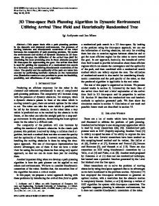
which a path search is calculated with a variant of the known A * algorithm modified A * algorithm which takes into account both the translation and rotation of the mobile robot [13]. Rao represents the environment populated by obstacles in the form of generalized polygons disjoint ground. A generalized polygon is constituted by a connected sequence of circle arcs and straight segments. Solving the problem occurs in three different ways: Graph visibility generalized Voronoi Diagram and generalized trapezoidal decomposition. The algorithm proposed by Rao, gives good results for solving the problems of navigation [18]. Brooks offers generalized cones to represent the free space whose complement is the space robot prohibited. It subdivides the space in the form of generalized and mobile robot moves along the axes of the cones [7]. Conte et al. have developed a path planning algorithm for a mobile robot based on a construction of distance fields. Each pixel of the image, a label that matches the length of the shortest path between the starting points is assigned. The advantage of such an approach is the obtaining of all the shortest paths connecting all points of the image at a starting point[14][15][16]. Elmesbahi et al. proposes to calculate the distance field on a broken end environment to reduce the execution time and the need for main memory [19][20]. Wesly et al. described the environment by a graph whose nodes correspond to particular points of the image. Arcs connecting two nodes with visible Euclidean distances as the arc lengths[1]. The graph produced is called the visibility graph. Asano et al. and Welzt worked in the same direction by developing a fast algorithm for constructing the visibility graph [5][10]. They made a pre-treatment to reduce the number of nodes considered in the visibility graph and uses the A * algorithm for finding the shortest path. Reducing the number of nodes is due to the approximation of obstacles by closed polygons and the fact of considering only the peaks corresponding to convex angles. 4) Genetic approaches Genetic approaches include work on the image as a data base of the problem by implementing several tools of Genetic Algorithm GA for image processing[23][24][25][28]. 5) Our approach Our approach is pictorial where a construction of the visibility tree is performed. Obstacles are dilated by the radius of the enclosing circle of the mobile robot. The mobile robot occupies a considerable area of the free space. But after expansion of the obstacles, the mobile robot is regarded as a point moving in the free space (Figure 1). The following processing is not performed on the original image but the result tree whose elements are specific points of the environment linked by the relationship of visibility. We built later a visibility graph on which we apply any scheduling algorithm. The path found is optimal. This approach is of great interest given its fast execution speed and minimizing memory requirements to implement such an algorithm.
(a)
(b)
Fig. 1. Obstacles are dilated by the radius of the enclosing circle of the mobile robot (a) The blackened area represents the forbidden space So be it moving. The mobile robot occupies a considerable area of the free space Sl. (b) After expansion of the obstacles, the mobile robot is regarded as a point moving in the free space Sl.
III.
PATH PLANNING WITH STATIC OBSTACLES
A. Principle The algorithm presented in this section, comprises three essential steps. The first step is to detect recursively individual points belonging to the assumed stationary obstacles. The second step reduces the number of points detected in the first step and therefore gives a visibility graph will be based on which to calculate the shortest path in the final stage.
Fig. 2. Principle of the process used to build the visibility tree
The construction of the tree is a recursive process visibility enabling a single data structure (binary tree), one element is linked with his son's relationship with visibility. Figure 2 illustrates the technique used for the construction of such a tree. X is an element of a visibility tree. It is the arrival point Y. If X is visible in the construction stops because the branch is terminal. If not, is slipped over the contour of the obstacle to the achievement of the two last visible point X (A1 and B1 in the case of Figure 1); then just do the same thing for point A1 and B1 to the end point Y. We repeat the process until the Y terminal as part of all branches of the tree visibility. Figure 2 provides an example of visibility tree element constructed from a given environment. This operation is repeated until connecting all pair of visible points of the global environment. Figure 3 illustrates an example of environment with obstacles and its tree of visibility. The visibility tree can be considered a multi-level graph.
88 | P a g e www.ijacsa.thesai.org
(IJACSA) International Journal of Advanced Computer Science and Applications, Vol. 5, No. 8, August 2014
B. Reducing visibility tree As shown in Fig. 4, two visible points can be connected in order to reduce the tree because the segment connecting two visible points is the shortest path. Each element of the tree is affected by an amount corresponding to the length of the shortest path from the starting point S.
Fig. 3. A populated obstacle environment is given with the starting point S and the point of arrival T. The tree of visibility is computed to represent this environment.
Fig. 5. Construction of final path
C. Shortest path construction The procedure for construction of the road is very simple. Each node of the tree takes a value corresponding to the distance from the start point S. Terminal node with minimal distance is selected. Other endpoints of the segments constituting the path correspond to take the fathers of nodes starting from selected T. The Figure 5 illustrates an example of the final path construction.
Fig. 4. Reducing the visibility tree with evaluation of different distances
D. Results To test the proposed algorithm, two different environments are chosen. The first is simple. You can see lots of free space between obstacles when there is no concave shape (See Figure 6). In the second, a concave obstacle includes the starting point (See Figure 7). The results are correct in both cases.
89 | P a g e www.ijacsa.thesai.org
(IJACSA) International Journal of Advanced Computer Science and Applications, Vol. 5, No. 8, August 2014
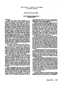
A. Extension of the Slip Algorithm Given the mobile obstacles in the plane (X, Y), the dimension “time” is used to define the position of obstacles in the space. This three-dimensional space is called Space-Time Representation. Each obstacle defined in Space-Time Representation is shown as prism form (See Figures 8 and 9). The static obstacles are orthogonal to the plane (X, Y) while the form of moving obstacles is oblique.
Fig. 6. The first example illustrates a path planning of a boat. Such an environment is populated by a group of islands seen as obstacles to what you can add boats supposedly immobile. The problem then is to determine the shortest path without collision from a starting point S to a point of arrival T. The obstacles are dilated by the size of the moving object (the boat in our case): the shaded area. Fig. 8. Environment 2-D captured at two different instants.
Fig. 7. The second example illustrates a path planning of a mobile robot in a world populated by a set of geometric constraints of any environment. The algorithm solves the problem without any influence of the shape of the obstacles on the execution time. The barriers also here are expanded by the size of the moving object.
IV.
ENVIRONMENT WITH MOVING OBSTACLES
In this section, it is assumed that the obstacles are moving along a linear trajectory with a constant speed. Those moving obstacles can be others mobile robots. As already mentioned, the problem of path planning for a mobile object at a constant speed in the presence of moving obstacles, is very tricky[21][22]. We show that our algorithm, presented in the previous section can be extended to find the path without collision with moving obstacles, the path is optimal; it is brought to the readers that the prismatic obstacles in the figures is chosen in order to facilitate the graphical representations execution. The barriers also here are expanded by the size of the moving object.
Fig. 9. In space-time environment representation, A and B have moved upon their speed directions therefor C stands at the same place
To find the path between S and T, the three-dimensional space is used. In this case, providing that the shortest path is comprised of straight line segments connecting the vertices visible of the obstacles is always true. Therefore, the algorithm uses the visibility graph and with the assumptions already made, a simple modification of our algorithm can find the path without collision over time. As the moving object moves at constant speed v and occupies a position W of the Time-Space Representation, it can jump to the possible positions defined by the surface of the cone (C) from the vertex W. This surface can be generated as follows (See Figure 10): - Constructing the vector which origin is W and making an angle with the plane (P) containing W with = arctan (v-1). .
- Sweep around this vector while keeping constant the angle
90 | P a g e www.ijacsa.thesai.org
(IJACSA) International Journal of Advanced Computer Science and Applications, Vol. 5, No. 8, August 2014
whereas the distributed model offers a worse solution in shorter computational time. Our approach can be considered as a method for finding optimal trajectories for multiple aircraft avoiding collisions. Developments in spacecraft path-planning have shown that trajectory optimization including collision avoidance can be drawn as a cubic form. An approximate model of aircraft dynamics using only cubic construction enables our approach to be applied to aircraft collision avoidance (See figures 12 and 13).
Fig. 10. The cone points representing the moving object can reach
Since there are obstacles (volume in space-time), the intersections of the edges of surfaces with cone (C) are interesting. A set called W-Visible containing all the points of the visible space under angle (), is used for the construction of the graph searched for our algorithm. These points define the W-Visible sequences under the angle and correspond to the vertices W-Visible in the plane (X, Y) (See figure 11).
Fig. 11. Determination of visible points on an obstacle with a 3-D slide
The formulation of our approach can also be extended to include multiple waypoint paths planning, in which each vehicle is required to visit a set of points in an order chosen within the optimization.
Fig. 12. Example of three trajectories that intersect on the same altitude
B. Complexity of the algorithm The complexity of the algorithm is determined in the worst case as follows: Each iteration of the algorithm consists of four steps. The first is to look for a node in the tree a set of points on the obstacle in O(n) operations. The second gives the set of pair of points visible under the angle in O(n) operations. The third step determines the extreme points in O(n) operations. The last step removes the points corresponding to the vertices obtuse O(n) operations. Then each iteration requires O(n) operations. The algorithm performs at most n iterations resulting in a worst case complexity of O(n2). This complexity increases if the moving object is supposed to have different speeds or obstacles change direction of movement repeatedly. V.
APPLICATION : AIRCRAFT TRAJECTORY PLANNING WITH COLLISIONS AVOIDANCE
Two specific models of aircraft trajectory path planning and optimization, centralized and distributed, have been examined and analyzed. Richards has models which solve this problem, each with their own respective benefits and drawbacks. Simulation results for each model and method have been presented in[29][30]. In general, the centralized model provides the best solution for multiple aircraft and collision avoidance,
Fig. 13. The representation of trajectories in space-time
VI.
CONCLUSIONS
The algorithm presented in this paper requires no pretreatment or constraints on geometric shapes of obstacles. In addition, the binary tree is a data structure accessible and easily feasible with any language. The first algorithm allows exploiting the latest work by using a small number of nodes to find the shortest path in a more improved while keeping the same time optimization criteria.
91 | P a g e www.ijacsa.thesai.org
(IJACSA) International Journal of Advanced Computer Science and Applications, Vol. 5, No. 8, August 2014
The extended algorithm determines a collision-free path is not necessarily optimal in the presence of moving obstacles. The environment is modeled in a space-time three-dimensional. As we found it difficult to simulate, a 3D viewing environment is being designed. In the future work, this approach can be applied to resolve several problems such as multi robot environment and multiple waypoint paths planning, in which each vehicle or robot is required to visit a set of points in an order chosen. [1]
[2] [3] [4] [5] [6]
[7] [8] [9] [10] [11] [12]
[13]
[14]
[15]
REFERENCES T. Lozano-Perez, M. Wesley, « An algorithm for planning collision free path among polygonal obstacles », Communication of the ACM, Vol. 22, no. 10, pp. 560-570,1979. T. Lozanno-Perez, « Spatial planning : a configuration space approach », IEEE Trans. Comput. , vol. 32, pp. 108-120, 1983. R.A Brooks, « Solving the find-path problem by good representation of free space », IEEE Trans. on SMC, vol. 13, pp. 190-197, 1983. J.L. Crowley, « Navigation for an intelligent mobile robot », IEEE J. Robotics automation, Vol. 1, pp. 31-41, 1985. G. Borgefors, « Distance transformations in digital images », Computer vision graphic image processing, Vol. 34, pp. 344-371, 1986. J. L. Crowley, « Dynamic world modeling for an intelligent mobile robot using a rotating ultrasonic ranging device », Proceeding IEEE Int. Conf. Robotics Automations, pp. 128-135, March 1985. R.A. Brooks, « A robust layered control system for a mobile robot », IEEE J. Robotics Automation, Vol. 2, pp.14-23, March 1986. M.G. Slack, « Planning path trough aspatial hiearchy: Eliminating stairstepping effects », Proceeding SPIE conf. Sensor Fusion, Nov. 1988. J.S.B. Mitchell, « An algorithmic approach to some problem in terrain navigation », Artificial Intelligent, Vol. 37, no. 1, pp. 171-201, 1988. J. Latombe, « Robot motion planning », Kluwer Academic Press, 1991. C. Alexpoulos, P.M. Griffin « Path planning for a mobile robot « , IEEE Trans. SMC, Vol 22, no. 2, pp. 318-322, March/April 1992. M.G. Slack, « Navigation templates: Mediating qualitative guidance and qualitative control in mobile robots », IEEE Trans. SMC, Vol. 23, pp.452-466, 1993. Kuo-Chin Fan, Po-Chang Lui, « Solving find path problem in mapped environment usind modified A* algorithm », IEEE Trans. on SMC, vol. 24, pp. 1390-1396, 1994. G. Conte, R. Zulli, « Motion planning and collision avoidance robots using distance field », Proceeding of the 3rd international workshop on robotics in Alpe-Adria Region, Bled, juil. 1994. G. Conte, S. Longhi, R. Zulli, « An algorithm for non-holonomic motion planning », Proceeding ISMCR, Slovakia, juin 1995.
[16] G. Conte, R. Zulli, « Hierarchical path planning in multi-robot environment with a simple navigation function », IEEE Trans. on SMC, vol. 25, pp. 651-654, 1995. [17] R. Kimmel, A. Amir, A. Bruckstein, « Finding shortest path on surfaces using level sets propagation », IEEE Trans. PAMI, Vol. 17, no. 6, pp. 635-640,1995. [18] N. S. V. Rao, « Robot navigation in unknown generalized polygonal terrains using vision sensors », IEEE Trans. On SMC, Vol. 25, pp.947962, 1995. [19] J. Elmesbahi, A. Raihani, M. Elkhaili, O. Boattane, « A region decompositon methode for path planning using a distance field », Proceeding IFIP-WG7, Noisy-le-grand, France, avril 1996. [20] J. Elmesbahi, A. Raihani, M. Elkhaili, « A fast algorithm for path planning problem using region decomposition » , Proceeding ITHURS96, Leon, Espagne, juillet 1996. [21] I.Ulrich, J. Borenstein, VFH* : Local Obstacle Avoidance with Lookahead Verification In IEEE int. conf. on Robotics and Automation, San Francisco, USA, 2000 [22] J. Thomas, A. Blair, N.Barnes, “Towards an efficient optimal trajectory planner for multiple mobile robots, Proceedings of the 2003 International Conference on Intelligent Robots and Systems, 2291-2296. [23] K.H. Sedighi, K. Ashenayi, T.W. Manikas, R. L. Wainwright, H.M. Tai, “Autonomous Local Path Planning for a Mobile Robot Using a Genetic Algorithm”, Proc. 2004 IEEE Congress on Evolutionary Computation (CEC2004), p. 1338-1345. [24] Kramer, J.,Scheutz, M., “Development environments for autonomous mobile robots: A survey”, C _Springer Science + Business Media, LLC 2006. [25] L. Montesano, J. Minguez, L. Montano. “Modeling Dynamic Scenarios for Local Sensor-Based Motion Planning”, Autonomous Robots, Vol. 12, No3, 231-251, 2008 [26] Meng, Rui, Su, Wei-Jun, Lian, Xiao-Feng. ”Mobile robot path planning based on dynamic fuzzy artificial potential field method” Computer Engineering and Design, Vol. 31, no. 7, pp. 1558-1561. 16 Apr 2010 [27] H.Adeli, M.H.N. Tabrizi, A. Mazloomian, E. Hajipour,M.Jahed, “Path Planning for Mobile Robots using Iterative Artificial Potential Field Method”, IJCSI International Journal of Computer Science Issues, Vol. 8, Issue 4, No 2, July 2011 [28] Tamilselvi, Mercy shalinie, Hariharasudan, “Optimal Path Selection for Mobile Robot Navigation Using Genetic Algorithm”, IJCSI International Journal of Computer Science Issues, Vol. 8, Issue 4, No 1, July 2011 [29] A. Richards, “Aircraft trajectory planning with collision avoidance using mixed integer linear programming”, American Control Conference, 2002. Proceedings of the 2002 [30] Matthew W. Zinn, “Analysis of Aircraft Trajectory Models with Collision Avoidance as a Mixed Integer Linear Program”, College of William & Mary, July 10, 2013
92 | P a g e www.ijacsa.thesai.org