Pattern-Based Design Recovery from Object-Oriented Languages to Object Process Methodology Dov Dori, Valeria Perelman, and Galia Shlezinger Technion, Israel institute of Technology
[email protected], {valeriya, galias}@tx.technion.ac.il
Abstract Keeping large software projects well documented is expensive and time consuming. Small code changes seldom propagate up to the design level. Therefore, design of large software becomes incoherent with the actual code. Yet understanding the (coherent) design is crucial for supporting the life cycle of the software. Reverse Engineering (RE) is the process of constructing a model of a system at a level that is more abstract than the source level at which the system is specified. In software, this amounts primarily to the system design from its given code. Most existing RE tools are UML-based. The majority of them recover only static aspects of the design, displayed by class diagrams. Others use pattern detection techniques to recover some of the high-level behavior. In this work, we argue that, modeling dynamic behavior of even moderately complex systems is hardly feasible with UML due to its lack of hierarchy. Alternatively, we propose RE that is based on Object Process Methodology (OPM), which provides a hierarchical view and a simple representation of design patterns.
1. Introduction While evolving and maintaining successful software systems during the 1970s accounted for 35 to 40 percent of the software budget, in 1980 the number raised to 60 percent [5]. Hence a very significant portion of the effort in a software product lifecycle, if not most of it, is spent on attempts to study and understand existing software code. In many cases, efforts are required due to lack of documentation describing the design of the system. In other cases, high premiums are paid to keep the legacy of the paper design current with the code, as even a slight code change must be appropriately reflected in the
Iris Reinhartz-Berger University of Haifa
[email protected]
documentation. The problem is exacerbated in many companies where tracking design changes and writing code are assigned to different professionals. Outdated design documentation leads to further difficulties in maintenance of the software and integration with other applications, and testing becomes more complicated as the application is further along its life cycle. These problems, which cause rapid deterioration of software, have pushed in recent years the evolution of reverse engineering (RE), which aims to analyze a subject system and to generate its representation at a higher, more comprehensible level of abstraction. This work focuses on the recovery and modeling of the system's design from its source code. Many commercial tools and scientific prototypes have been developed to address the RE task. Two common weaknesses of these tools are that they typically represent only the static aspects of the source code and that many of them are not fully automated. Reverse engineering entails that translation of large amounts of detailed source code be both complete (or lossless, i.e., without loss of information), and comprehensible, i.e., the resulting model should be communicable to humans who can make use of it with as little effort as possible. These completeness and comprehensibility requirements enforce stringent demands on the target model and its underlying methodology. OPM (Object Process Methodology) [1] is a prime target methodology for RE, as it is simple, hierarchical, and it describes the structure and behavior aspects of the system in a single graphical and textual model. The hierarchical structure of OPM makes it possible to model designs of large systems that have numerous possible scenarios. Additionally, since OPM ascribes equal status to objects and processes, prominent design patterns become unnecessary as they are built naturally into the OPM model.
Subsequently, OPM is an ideal choice for reverse engineering of code in general and one that is based on design pattern recognition in particular. The rest of the paper is structured as follows. Section 2 contains an overview of existing design pattern RE methods. In Section 3 we explain how OPM hierarchy can contribute to recovering the design of both the dynamic and the static aspects of the source code. In Section 4 we present OPM models of a prominent design pattern and demonstrate their simplicity and usability.
2. Reverse Engineering & Hierarchical Design Methodology A major RE challenge is coping with the large amounts of source code that comprise even medium-size software systems. Most commercial UML-based design tools, such as Rational Rose [6], Poseidon [7], and Together [9], support basic reverse engineering capabilities, such as class diagram and package tree generation. To handle the code size problem, these tools partition the classes by their packages such that a separate class diagram is generated for each package. While this may be a reasonable approach with respect to the system's structure, it is hardly suitable for modeling the dynamic design aspects. A sequence (or collaboration) diagram can be arbitrarily spread over a large number of packages, making it totally impractical to follow and understand. The FUJABA [10] environment supports generating all the UML diagram types, but it is semi-automatic and requires specific coding conventions. This limits its application only to programs that were initially designed with FUJABA and had all the code changes documented in a very specific form. Even if the programmers followed the documentation rules, the environment generates a large number of sequence diagrams that are hardly helpful to a human designer trying to understand the high-level system behavior. CodeLogic [8] is a commercial tool that solves this problem by modeling only class diagrams and providing the developer with the ability to choose a specific method, for which it generates a control flow and a sequence diagram. This approach still suffers from problems common to tools that do not support any dynamic view. It requires the human developer to decide what methods are important, which, in turn, requires that he or she perform manual code walkthrough and being involved in the design, defeating the whole purpose of RE. Although the UML-based tools surveyed above offer reasonable solutions for the static aspect of the model via class diagrams, none of them provide a satisfactory solution for the dynamic aspect, which is usually the more challenging aspect to comprehend from a given source code. Thus users of these tools are left with most of the
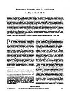
problem virtually unsolved. Two major causes for these tools weaknesses are that UML describes the dynamics of the system in a number of diagram types, which are separate from the static ones and most of them are not truly hierarchical. The resultant models are therefore large, use multiple models, and hence hard to follow and understand. The role of hierarchy in modeling system behavior is crucial, as it enables the designer to see the big picture as well as details at various detail levels. Easy traversal across detail levels is therefore of paramount importance to effective utilization of the hierarchical representation. Object-Process Diagrams (OPDs) are organized by construction in a hierarchical structure, where the root, called the System Diagram (SD), is the most abstract level. Refining (via zooming into a thing-process or object- or unfolding the thing) generates a new, lower level OPD in which the refineables (parts, features, specializations, or instances) are expressed along with their structural and procedural relations to surrounding things. The abstraction-refinement mechanisms ensure that the context of the process or object is never lost. In the following example (Figure 1 and Figure 2) we present a model of the system lifecycle and its’ evolution [1]. According to the OPM syntax processes are represented by ellipses and objects are represented by rectangles. The name of the process/object is written inside the figure. Objects and processes can be connected with structural relations (such as aggregation, generalization and so on) and procedural links (consumption, result, invocation and others). Figure 1 depicts the high-level abstraction of the system evolution. The diagram contains three objects: Customer, Environment and Benefit and one process: System Evolving. The Customer of the system is related to the Environment via aggregation; both of them are affected during the System Evolving process. This is depicted by the effect link between each object and the process. The same process yields Benefit of the system, which the Customer enjoys. As it could be seen no further details are given in the diagram. Figure 2 presents the same process zoomed-in. We can observe that it contains three sub-processes. The timeline in an OPD (Object-Process Diagram) flows from the top to the bottom. Hence, the Initiating process precedes the Developing process, which in turn precedes Deploying. The in-zoomed OPD contains more detailed information of how the Customer Environment and Benefit of the system interact with its’ sub-processes. Environment and Required Function Set are both instruments of the Initiating process. The Developing process affects the System and creates an Implementation, which is a part of the System. Sequentially, Implementation is an instrument of Deploying and finally the last sub-process creates Benefit.
Figure 2 presents both structural and functional aspects of the modeled system in the same diagram, while the transition from Figure 1 to Figure 2 demonstrates the ability to add detail by scaling down.
Figure 1: An OPM model for the System Lifecycle and Evolution
Figure 2: In zoomed OPM model of the System Evolving process
3. Design-Pattern Based RE Methods Detecting design patterns is a common approach to recover design from an object-oriented code (Java, C++, or C#). There are three reasons to reverse engineer objectoriented code to its OPM model using design patterns: Firstly, identifying design patterns helps the developer understand the reasons for the behavior of certain parts of the code. Secondly, identified patterns can be useful in clustering, as they can be out-zoomed to become super-nodes, thus enabling the construction of a comprehensible hierarchy of the systems’ model in OPM. Lastly, many known design patterns are built into OPM due to its high expressiveness and the use of processes alongside objects. Such patterns will be mapped onto the corresponding predefined OPM model fragment that integrates into the reverse-engineered OPM model.
There are four different approaches for an automated design patterns search [4]: 1. Identifying minimal key structures – The technique calls for the creation of a design patterns knowledge base. It saves for each pattern its minimal typical composition and some characteristics that should not be found in a pattern implementation. One tool that has implemented this method is SPOOL [12]. 2. Searching for class structures – This technique requires a complete match between class structures and pattern class structure. One research prototype that is based on this technique is IDEA [11]. 3. Fuzzy logic based search – The algorithms in this approach take into consideration different possible implementations for each design pattern. 4. Metrics based search – Assuming that each pattern comprises metrics that characterize it, this approach advocates calculating such metrics as depth of inheritance, class relationships, and number of classes sending messages to the observed class. Matching is based on the closeness between the expected and detected metric values. There are still many challenges in design patterns recognition in object-oriented code. As is the case typically in pattern recognition, each of the methods surveyed above suffers from a certain amount of positive false and negative true cases. Some patterns are so similar to each other, that they cannot be identified with a sufficient degree of certainty. Moreover, RE that based merely on design patterns is hardly practical, since programs consist of many other things in addition to patterns. The most promising technique according to [13] is searching for key structures of gang of four (GOF) patterns [2]. Based on this finding, our work searches for GOF pattern key structures. Our design recovery will also treat and model code for which no appropriate pattern was found. The simplicity of the OPM model plays an important role in a naïve, straightforward transformation of OO code to an OPM model for non-pattern code just as for the pattern-based code. Our approach is to create a knowledge base in OPM holding “signatures” for all the GOF patterns. Each such signature is a meta-model keeping both positive and negative search criteria. Positive search criteria happen with high probability in implementation of a particular design pattern, whereas negative one shouldn’t occur at all. Additionally the RE engine will hold a knowledge base standing for all the design patterns in OPM in their ObjectProcess oriented way. This knowledge base will be used to transfer the identified design patterns from ObjectOriented code to Object-Process oriented methodology (OPM).
While all the detected design patterns are mapped to the corresponding patterns from the knowledge base, the rest of the code will be transferred in the following manner: classes to OPM objects, their methods ignoring getters/setters to OPM processes and the relationships among them will be treated similarly to the approach described in [15]. 4.
Design Patterns in OPM 4.1. Modeling OO design patterns in OPM
This section demonstrates both the simplicity and expressive power of OPM as a target language from both pattern-based and non-pattern-based object-oriented code. We also show the adequacy of OPM as a means to create and manage a knowledge base of known patterns for the purpose of design patterns recognition. Traditional design patterns can be easily mapped to an understandable, readable and feasible OPM model for OO design patterns. A straightforward approach could be to model any design pattern in OPM. However, the result of this would be a hybrid model of an Object Oriented solution with OPM features. Such a model lacks desired characteristics of an effective, correct OPM model. Hence we propose modeling Object Oriented design patterns by modeling in OPM the problem they try to solve and analyze the resulting model. Some interesting questions that arise when we do this are whether the original problem still exists in OPM, and will the OO design pattern solution be also applicable to OPM? While we have already modeled the entire set of GOF design patterns [2], we have not encountered any pattern that could not be easily represented in OPM. Some of the patterns, though, lost their "raison d'etre", since the problem they were designed to solve does not exist in the OPM model in the first place. These patterns solve design dilemmas that are caused by the asymmetry in OO between processes and objects. Specifically, they solve problems that arise from the lack of independent process in OO. The solution they suggest is wrapping the process’ functionality in an object. Such an example is presented next.
4.2. The Command Design Pattern The Command design pattern [2] solves a relatively common problem. Consider the following motivation: A user interface tool kit is required to support various user operations. This tool kit contains several UI components,
such as menu items and buttons that should perform operations in response to the user's input. However, as the tool kit is an independent module, it cannot implement these requests. Only the application using this tool kit is familiar with what should be done in each operation and on which objects. The intent of the Command pattern, as noted in [2], is: "Encapsulating a request as an object, thereby letting you parameterize clients with different requests, queue or log requests, and support undoable operations.” Applied to the example above, the solution will entail adding a Command object, to be executed by a widget (which plays the role of the invoker) in the tool kit, while the concrete implementation of this Command object will be provided by the application using the tool kit (see Figure 3). The receiver of the command is the object in the application on which the command operates. Thus, when the User (Invoker) presses a menu item or a button, the Execute() method of the Command interface is called. This interface is implemented by the ConcreteCommand object, which is provided by the application. The ConcreteCommand object operates on a Reciever object in the application.
Figure 3. A UML model of the Command design pattern [2] The essence of this pattern is encapsulating an operation or a command in an object, which enables manipulating the command as a regular object. The OPM ontology comprises three types of entities: objects, processes and states. The first two, defined as things, are relevant to our discussion. Objects exist and can be viewed as equivalent to objects in the OO paradigm, while processes transform objects by generating them, consuming them, or affecting them, i.e., changing their state [1]. Both objects and processes can partake in generalization, aggregation, instantiation and exhibition relationships. When constructing a model for our example in OPM (Figure 4), we first recognize that the operations or
commands are processes. Their persistence is dynamic and they affect an object - the receiver. In our case, the receiver object exhibits these processes. Having Processes as stand-alone entities eliminates the need to artificially wrap a command inside an object. Modeling the receiver as the exhibitor (owner, in OO terms) of the commands is in most cases, the correct way to model our problem. However, adding or removing commands does change the exhibiting object (albeit to a small extent). A simple way to avoid this, modeled in Figure 5, is to add a level of abstraction, which consists of processes that are not exhibited by (not operations of) the receiver. These processes initiate the corresponding receiver's operations.
Figure 4. The OPM model of the Command design pattern
Figure 5. A more abstract OPM model of the Command design pattern Another feature of the command pattern is the common interface it has between the tool kit and the application. This is achieved in an OO model by having all commands inherit from a common abstract command object. The same can be done in the OPM model: all processes exhibited by the receiver may inherit from a common process. Thus, the achieved Command pattern representation is simple and native to the OPM model. Our RE engine will keep Command pattern model in its’ knowledge base and for each invocation of the process will map all the detected usages of the pattern in the code to the model. Such Command pattern translation could achieve comprehensive and more correct translation from the
object-process methodology viewpoint, in contrast to the straightforward one.
5. Conclusions The lack of a process entity that is equivalent to the object entity in OO is a major source of problems. Several behavioral design patterns were invented to solve different manifestations of this problem. We have presented an example of such a pattern above. One of the most prominent features of an OPM model in comparison to an Object Oriented model is that it is less coupled. This characteristic is demonstrated clearly in the Command OPM models in Section 4. Most of the reduced coupling is again a result of the existence of processes in OPM. OPM allows treating processes in the same way objects are treated. This eliminates the need for encapsulating processes in objects by making them operations of these objects (as suggested by the Command pattern). This, in turn, reduces the subclassing and complex object relationships that this solution creates. Cohesion and encapsulation are important in OPM, but since processes are equivalent to objects, a process is as independent as an object. Consequently, OPM does not view any object as an entity that must encapsulate methods if such encapsulation is not justified from a modeling viewpoint. This approach has proven to be more natural and suitable for modeling real world problems in general and, as we have seen, certain behavioral design patterns in particular. In conclusion, the OPM models of at least certain design patterns are more natural, understandable and simple than their OO counterparts. The built-in OPM hierarchy contributes to effective reverse engineering of a source code to a model. The powerful solutions provided by design patterns are in some cases inherent to the methodology. Consequently, the OPM model generated from source code by design pattern based recognition is made simple. A reverse engineering tool from Java code to OPM is currently being developed. Significant extensions to it could be: building language independent translation, identifying antipatterns [13], synchronization with an existent un-updated, partly valid OPM model of the source software and eventually re-tour engineering. We hope to suggest best practices for building OPM models, which can be used for re-tour engineering along with existing design patterns. Additionally, the OPM model gave us a fresh perspective on GOF patterns. We are now analyzing the patterns from this new point of view.
7. References [1] Dori D, "Object-Process Methodology- a Holistic Systems Paradigm", Springer, 2002. [2] Gamma E, Helm R, Johnson R, Vlissides J, "Design patterns – Elements of reusable Object-Oriented Software", Addison-Wesley 1994. [3] Aspect oriented software development. See: aosd.net [4] Philippow I, Streitferdt D, Riebisch M, Design Pattern Recovery in Architectures for Supporting Product Line Development and Application. In: Proc. 16th Intern. Conf. Software & Systems Engineering and their Applications ICSSEA '2003 Paris, Dec. 2-4, 2003. [5] R. Pressman, Software Engineering A Practitioner’s Approach. McGraw Hill, 1982. !!!(Hashmal 0211065) [6] Rational Software Corporation: [http://www.rational.com], November 2004. [7] Gentleware Company – homepage. [http://www.gentleware.com], November 2004. (Poseydon) [8] CodeLogic – homepage. [http://www.logicexplorers.com], November 2004. [9] TogetherSoft Corporation – homepage. [http//:www.togethersoft.com] [10] I. Rockel and F. Heimes. Fujaba – homepage. [http://www.fujaba.de], November 2004. [11] Bergenti, F., Poggi, A.: Improving UML design using automatic design pattern detection. In Proc. 12th. International Conference on Software Engineering (SEKE 2000), pp. 336-343 (2000). [12] Keller, R. K., Schauer, R. Robitaille, S., Page, P.: Pattern-based reverse engineering of design components. In Proc. Of the 21st International Conference On Software Engineering, pages 226-235, IEEE Computer Society Press, 1999. [13] Philippow, I., Naumann, S., Matthias, R., Streitferdt, D.: An approach for reverse engineering of design patterns, Springer-Verlag, published on-line 2004. [14] Andrew Koenig. Patterns and antipatterns. Journa of Object Oriented Programming, 8(1): 46-48, March 1995. [15] Seeman J., Wolf von Gudenberg J.: Pattern-Based Design Recovery of Java Software. 1998