Pattern-Based Development of User-Friendly Web Applications Ina Wentzlaff
Markus Specker
University Duisburg-Essen Faculty of Engineering Department of Computer Science Software Engineering Oststraße 99 47057 Duisburg, Germany
University Duisburg-Essen Faculty of Engineering Department of Computer Science Interactive Systems and Interaction Design Lotharstraße 65 47057 Duisburg, Germany
[email protected]
[email protected]
ABSTRACT Using patterns to preserve common problem-solving knowledge is a very popular approach. Each computer science community applies its own techniques to document engineering principles for the handling of recurring software development questions using patterns. Thus various pattern collections were evolved for dealing with specific problems of the respective community. As a result comparable patterns or redundant pattern descriptions exist in different collections leading unintentionally to a “reinvention of the wheel” time and again. Taking the development of a chat application as an example, we present an approach for integrating patterns from different software engineering disciplines. We transform problem patterns (problem frames) into solution patterns (design patterns) by using a case-based reasoning methodology to achieve a pattern-based software development process which systematically leads from natural language requirements to semi-formal near code level descriptions. We particularly consider non-functional software properties by combining design patterns of human-computer interaction (HCI) with software engineering (SE) patterns in order to support the systematic development of user-friendly software applications.
Keywords Software Engineering, Human-Computer Problem Frames, Design Patterns, Usability.
1.
Interaction,
INTRODUCTION
Patterns are abstract descriptions of recurring principles that reflect factual and experience knowledge. A pattern can be applied in different situations to solve concrete engineering problems. Hence, pattern-based development tech-
Copyright held by author/owner(s). ICWE’06 Workshops, July 10-14, 2006, Palo Alto, CA ACM 1-59593-435-9/06/07
niques can significantly contribute to the reuse of software engineering knowledge in all phases of the software development life cycle. Applying patterns to software design was leveraged by Gamma et al. [10] taking up the concept of Alexander et al. [2] who developed design patterns for architectures of buildings and town planning. Meanwhile pattern-based approaches are established in many computer science domains. Patterns are used to e.g. describe software development problems (problem frames [11]) and analysis tasks (analysis patterns [9]) in software engineering. Architectural styles and other patterns for software design (design patterns [5]), human-computer interaction problems (HCI design patterns [4, 14, 18]), and patterns for solving game design questions (game design patterns [3]) already exist. Often the same pattern can be found in several collections with different names, representations, or classifications [17]. For instance, comparing the HCI design pattern “(Multi Level) Undo” [18, 19] with software engineering design patterns a corresponding SE pattern can be composed of “Memento” and “Command ” [10]. These common redundant or comparable pattern descriptions indicate the possibility for integrating different pattern collections. Another important keynote is the way of describing patterns. Both, laymen and experts ought to be in the position to understand, and successfully apply patterns to build usable software artifacts. Therefore we share the concept of Tidwell [18] who strives to describe HCI design patterns so that it is comprehensible to layman. But like Folmer et al. [8] and Sinnig et al. [16] we see the need for extending informal pattern descriptions with technical details. Various development techniques and methods for constructing software are known from SE, which are mainly based on referring functional aspects. Many of these techniques are also used in Usability Engineering (UE). However, especially in UE there is an urgent need for considering nonfunctional software properties such as “usability” in a systematic way during the software development process (besides style guides and standards for software ergonomics). Actually, only few approaches [7] exist which explicitly take
non-functional properties (soft goals) into consideration. Nevertheless it is commonly accepted that software quality is mainly reflected by non-functional software characteristics [13]. In this regard patterns are generally no exception. They usually describe recurring software development principles in a mere functional way. However, they can also be assigned with non-functional characteristics: for instance, architectural styles have been classified according to software qualities as adaptability, performance, etc. [15]. HCI design patterns imply non-functional software properties such as usability. To ease the consideration of software quality aspects as usability during the entire software development process, we combine the problem description section of some HCI design patterns with patterns applicable in software analysis, namely problem frames. Problem frames (PF) are patterns developed by Jackson [11] which can be used for describing problems in the analysis phase of the software engineering life cycle (requirements engineering). They provide a means of representing functional software requirements by documenting necessary interactions between the “machine” (the software which is to be build) and its environment. A set of basic problem frames is available, which can be composed to reflect a given software development problem clearly and precisely. A frame diagram characterizes the respective problem frame and needs to be instantiated with the problem, which is described by the software requirements, to bring the pattern into action. We extend some frame diagrams by adding HCI-related problem descriptions. Software development problems modeled using problem frames maintain the concept that patterns should be applicable and comprehensible by layman, because they rely on the terminology of natural language requirements. In addition, applying a problem frame indicates explicitly, how to transform natural language requirements into descriptions that are sufficient for developing the machine (specifications). Associated with the fact that a problem frame can be specified with common software engineering techniques as the notations of the Unified Modeling Language (UML), our intention to describe informal patterns in a more technical way is supported. The main contribution of this article is to demonstrate how problem descriptions from HCI design patterns become integrated into problem frames obtaining HCI problem frames (HCIFrames). These new HCIFrames facilitate identifying and representing HCI relevant problems already in requirements analysis. Hence, the application of commonly known HCI design patterns is guided during software design. The mapping of HCI-oriented problem patterns to patterns for describing solutions (as architectural styles and design patterns) is assisted by a case-based reasoning process. This is supplied by a repository comprising cases of patterns used in the software analysis phase and linked with appropriate patterns used in software design. By joining HCIFrames and patterns for software design we achieve a pattern-based software development process, which preserves software quality characteristics as usability through
the software development life cycle. Additionally, it provides a methodological approach to make HCI design patterns implementable. This article is organized as follows. Sect. 2 describes how a pattern-based software development process can be obtained by adopting case-based reasoning (CBR). With CBR a smooth transition of problem patterns for software analysis into suitable solution patterns for software design is accomplishable. To demonstrate the effectiveness of our approach, we exemplify the development of a chat application in Sect. 3. Starting from the natural language requirements in Sect. 3.1 we model the overall problem situation with a context diagram in Sect. 3.2. In Sect. 3.3 we decompose the software development problem into simple subproblems by means of problem frames and introduce their fundamental notations. In order to consider software quality aspects already in the early phases of software development, we extend the problem frames, which are relevant to our application example, by HCI-oriented problem descriptions in Sect. 3.4. This results in the derivation of HCIFrames. Sect. 4 illustrates how the content of a problem pattern can be used for instantiating a corresponding architectural style or design pattern and for obtaining a concrete solution to the given software development problem. Sect. 4.1 particularizes the transformation of problem frames into UML class diagrams. Sect. 4.2 outlines where software quality characteristics are preserved in detail, by stating explicitly the respective elements in the HCIFrame instances and corresponding elements of an UML class diagram. Sect. 4.3 shows how the pattern-based software development process is effected by case-based reasoning. Finally Sect. 5 gives a conclusion and our perspectives.
2.
METHODOLOGICAL ASSISTANCE BY CASE-BASED REASONING
Case-based reasoning is a problem-solving paradigm. It originates from knowledge engineering [1]. In CBR, a case consists of a known problem and a corresponding solution. A case base is used as a repository collecting these cases. The process of CBR often referred to as the R4 -cycle consists of the following steps. Retrieve: Based on the description of a given problem (new case) the case base is browsed in order to identify already existing cases which match with the new case. Reuse: As cases are compositions of a problem with a corresponding solution, the solution of the retrieved cases is reused to solve the given problem. Because a new case can be matched with several existing cases, different solution alternatives can arise and be taken into account for solving the given problem. The problem, which is described in the new case and combined with the solution of the retrieved case, represents a solved case. Revise: The suggested solutions are tested for applicability and if necessary adapted to meet the problem demands (tested/repaired case).
Retain: If a tested or repaired case could successfully be used to sort out the given problem, it is stored for future reuse in the case base (as a modification of some existing cases or a new learned case).
case *
3.1
solution pattern
identify abstract standard problem
abstract standard solution Revise & Retain
case base generalize concrete problem
DEVELOPING A CHAT APPLICATION
In order to show how user-friendly software can be developed systematically with our suggested pattern-based methodology, in Sect. 3.1ff we begin with the definition of informal, natural language requirements for the chat application. In Sect. 3.3ff we detail the usage of problem frames and their relations to non-functional software properties in the context of human-computer interaction design. The transformation of problem patterns into solution patterns is introduced in Sect. 4.
Understanding the problem situation
The system mission of the chat application can be outlined as follows:
problem pattern
Retrieve & Reuse
3.
choose adapt
concrete solution
“A text message-based communication platform shall be developed which allows multi-user communication via private I/O-devices.” To describe this software development goal more precisely we derive further requirements R1-R6 as optative statements in Tab. 1. The requirements describe desired properties of the environment, after the machine is in operation [11]. Moreover domain knowledge, which is subdivided into facts F1 and assumptions A1, is recorded. Facts represent fixed characteristics of the application domain, whereas assumptions describe constraints for the application environment. Both, facts and assumptions are indicative statements, which are needed to realize the requirements during the implementation process. R1 R2
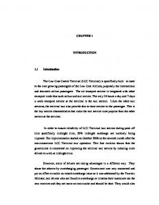
Figure 1: A pattern-based SE process with CBR
R3
Fig. 1 illustrates a customized version of the CBR cycle to implement a pattern-based software engineering process. A case is composed of a problem frame (as an abstract standard problem) and an accordant architectural style or design pattern (as an abstract standard solution). That is why the case base primarily consists of connected patterns.
R4
The concrete problem is generalized to a standard problem by instantiating a problem frame. The case base is browsed to retrieve cases whose problem pattern coincide with the problem frame that is used to represent the concrete problem. So corresponding solution patterns (architectural styles or design patterns) can be identified by means of the retrieved cases and reused for solving the given problem.
F1
The most suitable solution pattern for the given problem situation is chosen and instantiated with the content of the connected problem frame. Thus the instance of a solution pattern represents a concrete solution of the given problem. Sometimes it is required to adapt a solution pattern or if the case base does not provide any solution patterns to develop a new one. At last the revised case, with which the concrete problem is successfully solved, is retained and the case base is updated. In this way we shift the pattern-based software development process to the level of standard problems and related standard solutions.
R5 R6
A1
All users can phrase text messages. The phrased text messages are presented on a graphical display. Users send their phrased text messages to the chat in order to take part in the chat. Text messages taking part in the chat are registered to the course of chat in their correct temporal order. The course of the chat is presented on the graphical display. Sending text messages changes the graphical display presentation of the course of the chat. Users can only understand the course of chat, if the text messages are presented in the correct temporal order (First In - First Out (FIFO)). Users will follow the course of chat on the display.
Table 1: Requirements and domain knowledge for the chat application For our application example we assume that the requirements and the domain knowledge are completely recorded in Tab. 1.
3.2
Capturing the problem situation
Fig. 2 shows a context diagram [11], which represents the overall problem situation by interactions between the machine (the software, which is to be developed) and its application environment. Knowledge extracted from the requirements and domain knowledge (cf. Tab. 1) is represented within the context diagram with domains (rectangles) and sets of shared phenomena (labeled links between the domains).
text message
Fig. 2, this pattern instance contains only domains and shared phenomena, which are relevant to fulfill the requirements R1 and R2 (cf. Tab. 1).
d course of chat
c
chat application b
a
user
e
display a: {phraseTextmessage, sendTextmessage} b: {showTextmessage, showCourseOfChat} c: {registerTextmessage, CourseOfChat} d: {editTextmessage, MessageText} e: {followCourseOfChat}
Figure 2: Context diagram for the chat application The domains correspond to entities of the real world and can be divided into the following categories: The machine domain (rectangle with two vertical lines) represents the software product which ought to be developed, in our case the chat application itself. Data structures, database scheme, or other representations of information relevant to the problem and thus need to be represented by the machine are build by the software developer and centralized in designed domains (rectangle with only one vertical line), e.g. here the text message. Given domains (simple rectangle) are concepts of the real world, which already exist and do not need to be constructed artificially. They are relevant for the problem description and its solution and need to be considered in the context diagram, as well; in this case the display. Shared phenomena are operations, actions, events, or states that combine two domains with each other. For instance, the machine domain chat application shares the phenomena of set c: {“register text message” (R4) and “content of the course of the chat” (R3-R6)} with the designed domain course of chat.
3.3
Decomposing the problem situation with problem frames
Now we decompose the context diagram by means of knowledge-based projection into smaller, parallel subproblems. Those simple and independent subproblems are represented by instantiated problem frames. For each subproblem, all other subproblems will be considered as already solved (separation of concerns). The subproblems are derived from the context diagram using operators for decomposing problems (e.g. by combining domains or omitting shared phenomena). To simplify matters we show a pattern and its instance in one common diagram. Elements belonging to the frame diagram of the pattern are italicized; all other elements belong to the pattern instance. Fig. 3 shows the instance of the problem frame “commanded workpiece display”. Its frame diagram is a variant of the “commanded display” frame developed by Jackson [11] and an enhancement of the “update” frame developed by Choppy and Heisel [6]. In comparison to the context diagram in
The ellipsoid in Fig. 3 links the requirements (R1-R2) to the problem context (dashed lines to the domains). Shared phenomena at the interface of the machine domain relate the problem context to the software which has to be developed. Reading a frame diagram from right to left sets a visual trace of how natural language requirements become technical descriptions, which suffice to develop the machine (specifications, cf. Fig. 12). Only shared phenomena, which are directly related to the machine, can be controlled or observed by the software, which is to be constructed. These shared phenomena can be implemented for satisfying the requirements. The arrowhead at dashed lines represents a constraint on the corresponding domain (concerning behavior or characteristics of this domain stated in the requirements). For instance, the requirement R1 “users phrase text messages” describes a restriction on the domain text message, because only the user decides on the content of the text message. workpiece
text message X
TM!Y2 CA!E1 chat application commanded workpiece display machine
Y4
display
CA!E2
display
Y5 C
R1, R2
operator
U!E3
user
E3 B
E1: editTextmessage E2: showTextmessage E3: phraseTextmessage / "user phrases text message" Y2: MessageText Y4: "content of text message" Y5: "display text message"
Figure 3: Instance of the “commanded workpiece display”
problem
frame
The characters Y and E characterize shared phenomena. A Y indicates symbolic values, while events are annotated with an E. The characters are numbered for indexing the shared phenomena. The letters X, C, and B at the domains characterize the domain type. Thus the designed domain text message is a lexical domain X that works up symbolic phenomena. The display is a given causal domain C, which does not need to be developed, but can be controlled according to our wishes. A biddable domain symbolized by the character B represents the user. His behavior cannot be predicted or controlled by the machine. Indeed the user can make inputs to the software, but cannot be forced by requirements to act in a predetermined way. However, assumptions as part of the domain knowledge are used to record the assumed user behavior. The exclamation mark (!) at the shared phenomena denotes which domain controls a shared phenomenon. However, this does not imply control flow. The notation TM!Y2 in Fig. 3 in fact expresses that the domain text message (TM)
is responsible for administrating the symbolic phenomenon “content of text message” at the interface Y2. The machine domain controls requests for the “content of text message” (MessageText). The problem frame “commanded workpiece display” in Fig. 3 describes the following problem situation: If the operator (user) sends a command to the machine (“phrase text message” at the interface E3) the machine changes the workpiece (text message) on behalf of the operator (E3 phenomena imply E1 phenomena). The machine can follow the state changes of the workpiece (text message) (Y2: “content of text message”) and represents them on a display (display) (through phenomena of the interface E2: “show text message”).
3.4
Considering usability aspects with HCIoriented problem descriptions
To cover software quality aspects by means of problem frames we now detail the patterns, which are used in the different subproblems of Fig. 3 to Fig. 5, for reflecting usability demands. For this purpose we adopt problem descriptions of HCI design patterns from Tidwell [18], van Welie [19], and Rossi et al. [14] to the problem frames approach of Jackson [11]. Fig. 6 extends the standard problem “commanded workpiece display” of Fig. 3 by the HCI design patterns input hints: “place a sentence to explain what is required” (workpiece meta information) and input prompt: “prefills telling the user what to do” (workpiece default) from Tidwell [18].
Apart from this first subproblem represented by an instance of the problem frame “commanded workpiece display” in Fig. 3 there are further instantiated problem frames covering the remaining requirements. For the sake of completeness we only draft them in Fig. 4 and Fig. 5.
workpiece default
default text mes. X
commanded transformation machine
CA!E1
text message X course of chat X
Y2 Y5
user
R3, R4
E3 B
E1: registerTextmessage E3: sendTextmessage / "user sends text message to chat" Y1: MessageText Y2: "content of text message" Y5: "content of course of chat"
Figure 4: Instance of the “commanded transformation”
problem
frame
course of chat X
Y6
display
chat application commanded model display machine
CA!E2
display
Y4 C
R5, R6
operator
U!E3
user
E3 B
E2: showCourseOfChat E3: sendTextmessage / "user sends text message" Y4: "show course of chat" Y6: "content of course of chat" Y7: CourseOfChat
Figure 5: Instance of “commanded model display”
the
chat application commanded workpiece display machine
Y4
display
CA!E2
display
Y5 C
R1, R2
operator
U!E3
user
E3 B
E1: editTextmessage E2: showTextmessage, showMetaInfo, showDefault E3: phraseTextmessage / "user works on text message" Y2: MessageText, Meta, Default Y4: "content of text message" Y5: "show text message" Y8: TextMessageMetaInfo Y9: MessageTextDefault
Figure 6: Instance of the HCIFrame “commanded workpiece display”, cf. Fig. 3
model
CC!Y7
text message X
TM!Y2 CA!E1
operator
U!E3
OM!Y8 workpiece
model
chat application
descript. of text mes. X
DT!Y9
model
TM!Y1
workpiece meta information
problem
frame
The HCIFrame instantiated in Fig. 6 describes the following situation: if the operator (user) has so far not commanded the machine (chat application) by E3 phenomena, then the workpiece default (default text message, e.g. ) is displayed via the shared phenomena MessageTextDefault at the interface Y9 and Default at the interface Y2 on the display. The default text message acts as a placeholder for the MessageText of the workpiece text message, which still needs to be phrased by the user. In addition to the content of the workpiece (text message) workpiece meta information (a description of the kind of expected inputs, e.g. the caption “Your text message:”) is displayed (realized by phenomena of the interfaces Y8 and Y2). Apart from the two new domains workpiece default and workpiece meta information the behavior of this HCIFrame does not differ from the problem description of the problem frame “commanded workpiece display” in Fig. 3.
The HCI design pattern progress “tell user whether or not an operation is still performed and how long it will take” appears in different pattern collections and with different names (“process feed-back” Rossi et al. [14], “progress” van Welie [19], and “progress indicator” Tidwell [18]). Fig. 7 shows the HCI-oriented extension of the standard problem “commanded transformation” of Fig. 4 using the HCI design pattern problem description of progress. The HCIFrame “commanded transformation” in Fig. 7 extends the description of the standard problem situation in Fig. 4 as follows: initiated by an E3 command of the operator (user), an internal machine working process (Y1 to E1) is initialized. On a transformation display (display) the operator can observe that the machine is still operating (E2). The operator does not need to know how the working processes are implemented, but he can initialize and observe them. transformation display
CA!E2
display
C
text message X
4.
DESIGN OF THE PROBLEM SOLUTION
Transforming problem patterns such as problem frames to solution patterns like architectural styles or design patterns facilitates a systematical derivation of near code descriptions primarily based on natural language software requirements. The content of the instantiated problem frames derived in the analysis phase is now used to assign concrete values to corresponding architectural styles or design patterns and thus instantiating them. The structural extensions of HCIFrames are accordingly used to give additional quality related structure to corresponding solution patterns. This results in a more detailed specification of an adequate solution for the given software development problem maintaining the specified quality characteristics.
model
TM!Y1
laymen, as well. Software requirements described in a natural language style can be simply expressed by domains and related shared phenomena. Fitted into an appropriate problem frame important entities and their relations are emphasized in order to detail the subproblem situation and derive technical descriptions, which suffice to develop the desired software.
Y2
model
chat application commanded transformation machine
CA!E1
course of chat X
Y5
workpiece model
TC!Y7 CA!E1
R3, R4
operator
U!E3
user
E3 B
E1: registerTextmessage E2: showTransformationInProcess (Y2 to Y5) E3: sendTextmessage / "user sends text message to chat" Y1: MessageText Y2: "content of text message" Y5: "content of course of chat"
Figure 7: Instance of the HCIFrame “commanded transformation”, cf. Fig. 5 By integrating problem descriptions of HCI design patterns into problem frames, it is possible that software quality attributes like usability can already be considered in the early stages of the software development process. The basic functionality of the chat application covered in the problem frames of Fig. 3 up to Fig. 5 is improved by usability aspects represented in the HCIFrames in Fig. 6 and Fig. 7 (by offering more feedback through input hints, input prompts and indication of internal machine working processes to the user). Identifying non-functional software attributes like usability and its corresponding functions already in an early software development phase provides a valuable base for systematically developing user-friendly quality software during the next phases of the software development process. The analysis of the software development problem is now completed. In the next step the frames are transformed into solution patterns preserving the identified usability aspects. This should be supported by CBR in the future. However, the descriptions of the new HCI-oriented problem patterns are still kept informal, so that they are understandable for
text m. & coChat X
Y6
view
chat application MVC machine
CA!E2
display
Y4 C
R1−R6
controller
U!E3
user
E3 B
E1: editTextmessage, registerTextmessage E2: showTextmessage, showMetaInfo, showDefault, showCourseOfChat, showTransformationInProcess E3: sendTextmessage, phraseTextmessage / "user input" Y4: "show text message and course of chat" Y6: "content of text message and course of chat" Y7: MessageText, TextMessageMeta, MessageTextDefault, CourseOfChat
Figure 8: Instance of a problem frame for the architectural style “model-view-controller” Rapanotti et al. [12] introduced architectural frames (AFrames) in order to anticipate architectural design considerations already in the software analysis phase. Comparable to this approach in Fig. 8 we develop a problem frame that reflects our interpretation of an AFrame, which expresses the architectural style “model-view-controller” (MVC) of Buschmann et al. [5]. Taking the domains and shared phenomena of the problem frames in Fig. 5, Fig. 6 and Fig. 7 into account we instantiate the MVC problem frame in Fig. 8, which summarizes their property and behavior descriptions. The MVC problem frame in Fig. 8 can be mapped to the UML class diagram of the corresponding “model-view-controller” architectural style without any changes to the original classes Model, View, and Controller. They remain unchanged, as shown in Fig. 9.
Observer
chine, here: the chat application itself. The user controls phrasing or sending text messages through the chat application, which treats these requests as a kind of Controller.
update call update Model coreData setOfObservers attach(Observer) detach(Observer) notify
View myModel myController attach initialize(Model) getData makeController activate display update
getData service
Controller create manipulate myModel display myView initialize(Model,View) attach handleEvent call service update
Shared phenomena that are controlled by lexical or causal domains become simple attributes of the corresponding classes. For instance, the shared phenomenon CourseOfChat at the interface Y7 in Fig. 8, which is controlled by the domain course of chat becomes an attribute of the class course of chat, which stores the content of the actual course of the chat.
chat application text message MessageText TMMetaInfo MTDefault editTM
course of chat CourseOfChat registerTM
display TMDisplay CoCDisplay TiPDisplay
phraseTM sendTM control user
Figure 9: Architectural style “model-viewcontroller” assigned with content of the problem frame in Fig. 8
4.1
Transformation of problem frames into UML class diagrams
All requirements R1-R6 of Tab. 1 are covered in the UML class diagram in Fig. 9. This class diagram is an instantiated solution pattern which contributes solving the given software development problem. It is possible that the domains of the problem frame in Fig. 8 are related to the class diagram by an inheritance relation, which is based on their respective role (if they were instances of model, view, or controller ) in the problem frame. For example the domains text message and course of chat are a kind of Model in the UML class diagram (as well as in the problem frame) providing different services and work on different sets of core data (class attributes). Shared phenomena controlled by the machine become operations of the other, corresponding domains participating in this interaction. For instance, the shared phenomenon at the interface E1: editTextmessage, which occurs in the subproblems described in Fig. 3 and Fig. 6, becomes a service of the class Model in Fig. 9 and will be implemented by the operation editTM of the inheriting class text message. The shared phenomena at the interface E2: showTextmessage, showCourseOfChat, and showTransformationInProcess in Fig. 8 are not explicitly stated as operations of the class display, since they are only different types of realization of the display operation of the class View. We assume that the overall display, which is visible for the user, consists of several subdisplays (reflected by the role names TMDisplay, CoCDisplay and TiPDisplay). These subdisplays might handle different aspects, which should be displayed, like showing the text message, showing the actual course of chat, etc. However, this assumption does not contradict with our systematic pattern transformation approach. Shared phenomena of biddable domains cannot be controlled by the machine, but they can request services or initialize events. Thus shared phenomena controlled by a biddable domain (here: the user) are assigned to services of the ma-
4.2
Informal HCI design patterns as part of the semi-formal design solution
Fig. 9 reflects a coarse-grained design solution for the software development problems specified in Fig. 5 to Fig. 8. By combining the informal HCI design pattern problem descriptions of Tidwell [18], van Welie [19], and Rossi et al. [14] with problem frames, which are used in requirements engineering, we are now able to systematically state where design patterns can be applied in the design of the software solution and how software quality aspects such as usability have to be realized. In contrast to Sinnig et al. [16], who transform HCI design patterns into UML class diagrams, we do not need explicit UML representations of single HCI design patterns. Our approach has the following benefits: First, we can reuse the natural language descriptions of the original problem descriptions of HCI design patterns in the analysis phase of the software development process and thus support both, laymen and experts working with patterns. Second, we are in the position to systematically state where and how HCI design patterns should be applied in order to realize the software product. HCIFrames can explicitly show, which part of the software is affected by usability aspects. By transforming HCI-oriented problem patterns into solution patterns like architectural styles or design patterns, the designer is guided to the place where design patterns can be applied instead of introducing them artificially only based on personal experience. Thus our approach supports identifying design solutions by giving hints regarding how and where design patterns should be applied. In Fig. 9 the HCI design patterns “input prompt”, “input hint”, and “progress” are part of the designed solution. The class text message has two new attributes namely TMMetaInfo and MTDefault, which are derived from the corresponding HCIFrame in Fig. 6. If the operation display of the class View is called, the TMDisplay shows the MessageText of the class text message as well as the content of the attributes TMMetaInfo (possibly as a label of the text message) and MTDefault (for example as an initial value of the MessageText). The reader could envisage a labeled text field widget, which allows the manipulation of a text message. It represents the text message on the TMDisplay.
4.3
Applying CBR to identify appropriate problem solutions
One objective of applying case-based reasoning to our pattern-based software development process is to identify different possible solution patterns, which fit the given prob-
lem situation, and use the most appropriate one(s) to realize the problem solution. Rating different design alternatives by using metrics and CBR could be one approach to handle several retrieved solution patterns. We have decided to use several solution patterns and combine them into an overall design. Until now only human-computer interaction problems have been considered in the application example. They belong to a problem class which often corresponds to a “model-view-controller” structure. Further investigations of the problem situation are necessary for a close understanding of the communication problem that needs to be solved by our chat application (cf. system mission in Sect. 3.1). forwarder/receiver
BT!C4 CA!C2
Bluetooth
C
C6
workpiece model
chat application forwarder receiver machine
CA!E1 TC!Y1
text m. & coChat X
Y5
R3, R4
operator
U!E3
user
E3
the application domain. In our application example a chat application for mobile devices shall be developed, so that a Bluetooth domain is responsible for administrating the forwarder-receiver tasks. The “forwarder-receiver” problem frame in Fig. 10 describes the following problem situation: Based on an operator (user) command (E3: sendTextmessage) and the actual state of the machine (chat application) indicated by phenomena Y1 controlled by workpiece models (here: MessageText of text message), the machine requests the forwarder/receiver domain (Bluetooth) to call C2 operations: sendMsgText corresponding to the E3 command. In its role as forwarder the domain forwarder/receiver is a kind of required interface, which initializes operation calls, whereas in its role as receiver the domain forwarder/receiver is a kind of provided interface, which implements the behavior of the called operations. If a forwarder/receiver receives a message (i.e. a service of the receiver is used by a forwarder), it forwards the receiveMsgText command (C4) to the machine, which processes the corresponding registerTextmessage operations (E1).
B
E1: registerTextmessage E3: sendTextmessage / "user sends text message to chat" Y1: MessageText Y2: "content of text message" Y5: "content of course of chat" C2: sendMsgText C4: receiveMsgText C6: "text message published to all chat users"
Forwarder sendMsg Peer n service receiveMsg
Figure 10: Design pattern “forwarder-receiver” assigned with content of the problem frame “commanded transformation” in Fig. 4
IPC
marshal deliver sendMsg 1:1 Receiver receive unmarshal receiveMsg
IPC
chat application
Fig. 10 shows an instance of the problem frame “forwarderreceiver”. The shared phenomenon sendTextmessage and its related phenomenon registerTextmessage are responsible for publishing the private phrased text messages to all users of the chat. The “forwarder-receiver” problem frame is a problem pattern that reflects the need of distributing information between different users or applications by introducing an intermediate forwarder-receiver component. This component handles the communication. A new domain Bluetooth could be identified by a further analysis of the chat application domain. The new facts F2 and F3 about the application domain can be collected in the domain knowledge for the chat software. F2: The chat application shall run on mobile devices. F3: Mobile devices communicate via Bluetooth. This new domain knowledge indicates that collecting facts and assumptions about the application domain is an important issue. If the software development goal (system mission and requirements) is the development of a chat application for a desktop PC with an Internet connection, the new forwarder-receiver domain can be a W-LAN connection or the use of TCP/IP, etc. In this case a client-server architecture would possibly better suit the given properties of
sendTextMessage
Bluetooth
W−LAN
SMS
Figure 11: UML class diagram for the design pattern “forwarder-receiver” assigned with content of the problem frame in Fig. 10 Thus we achieve a peer-to-peer chat application, in which the machine can be client as well as server depending on the corresponding service that is processed. Again there is no need to change the original design pattern “forwarderreceiver” of Buschmann et al. [5]. The content of the problem frame in Fig. 10 can be combined with the design pattern in Fig. 11 by a simple inheritance relation. After the text message is sent to all other users of the chat, the problem frame in Fig. 5 is responsible for displaying the new, incoming text message by updating the course of chat on the private user displays. Like the problem frames of the analysis phase the two instantiated solution patterns of software design namely the architectural style “model-view-controller” in Fig. 9 and the design pattern “forwarder-receiver” in Fig. 11 are independent (sub)solutions to the given problem situation. These concurrent solution representations finally have to be combined in order to describe a design that represents a near code level description of the software, which is to be real-
ized. We use UML sequence diagrams for composing the overall design out of the parallel (sub)solutions.
sd chatApplication :user
:chat application
:text message
:course of chat
:display
:bluetooth
alt phraseTM editTM Fig. 6
Textmessage
display(showTextmessage,showMetaInfo,showDefault) sendTM getData Fig. 7
Textmessage par
sendMsgText(Textmessage)
Fig. 10
display(showTransformationInProcess)
Fig. 7
receiveMsgText(Textmessage) opt
display(cancelTransInProcessInformation) registerTM getData
Fig. 7 CourseOfChat
Fig. 5
display(showCourseOfChat)
Figure 12: UML sequence diagram for specifying the chat application software
The UML sequence diagram in Fig. 12 is derived by using the problem frames in Fig. 5, Fig. 6, Fig. 7, and Fig. 10. Domains of the problem frames are now objects of the sequence diagrams. The messages in Fig. 12 are taken from the UML class diagrams of Fig. 9 and Fig. 11. Remember that they were derived from the shared phenomena of the corresponding problem frames. The requirements R1-R6 were used to define the time order of the messages in the sequence diagram. Now we have a specification of the chat application machine, which can be easily used for developing the software.
5.
CONCLUSIONS AND PERSPECTIVES
The integration of patterns from different computer science disciplines enables a systematic transformation of natural language problem descriptions into solution descriptions, which are close to the software implementation level. For this we employ repeating and comparable pattern descriptions from HCI and SE in order to realize a pattern-based software development process. Problem frames are used to represent a software development problem to be solved. Architectural styles and design patterns are used to reflect possible solutions of these software development problems. Based on an application example, we showed how problem frames as problem patterns can be transformed into architectural styles and design patterns as representatives for solution patterns, in order to finally implement given software requirements.
In addition to the systematic transformation of software artifacts of the analysis phase to software artifacts of the design phase, we explicitly refer to non-functional software properties and improve the application of HCI design patterns within the overall software development process. Therefore we integrate the problem descriptions of some HCI design patterns into problem frames obtaining HCIFrames. Thereby software quality attributes such as usability become representable in early software development phases in an explicit manner. Nevertheless our HCI-oriented problem representations remain in natural language, understandable by experts and laymen. Apart from the core functionality of the software that is to be developed, (HCI)Frames can be systematically transformed into architectural styles and design patterns. For our chat application example we demonstrated the qualitative improvement of the desired functionality. A problem pattern as shown in Fig. 8 in combination with its corresponding solution pattern in Fig. 9 represents a pattern case, which can be stored into a pattern case base and reused by CBR techniques to solve different problem situations. CBR techniques could also make suggestions concerning the most appropriate solution for a given application example. Currently, we extend the chat application example and analyze the relevance of the domain knowledge for the choice of patterns and its role considering software quality characteristics. Tool support for the transformation of problems into solution patterns is planned for the future. The applied problem decomposition technique using knowledge-based projection eases the further development of the application example in an evolutionary style. New requirements are assigned to already existing subproblems or a new problem frame represents the problem situation the new requirement is involved in. In contrast to use-cases, problem frames explicitly show the transformation of natural language requirements to interactions of the machine with the corresponding entities of the environment. A problem frame can be translated into objects and messages of a UML class or sequence diagram. Starting with Jackson’s context diagram and problem frames in the analysis phase, provides the distinction of natural language problem descriptions from (semi)-formal, technical (for instance, UML) representations of a detailed solution to a given problem in the design phase. A deterministical transformation of a problem frame into a UML diagram is possible. Furthermore, we are interested in investigating how HCIFrames can be combined with graphical user interface (GUI) design elements (like a button, check box, text field, etc.) to assist the development of user-friendly applications. Fig. 3 for instance could be usefully implemented through a labeled text field widget with a default text shown on initialization time of the text field. Extending our pattern-based software development process in an aspect-orient way combined with the idea of model-driven architecture would lead to a rapid software development process where based on frames core system functionality and a prototypical GUI can be developed in parallel and implemented by corresponding components. This vision is part of our future work.
6.
ACKNOWLEDGEMENTS
The authors appreciate the in-depth comments given by the anonymous reviewers to improve this work as well as the encouragement provided by our colleagues Ren´ee Foraschick, J¨ org Niesenhaus, Isabelle Cˆ ot´e, and Holger Schmidt. We would like to thank our doctoral thesis supervisors Prof. Dr. Maritta Heisel and Prof. Dr.-Ing. J¨ urgen Ziegler for their support.
7.
REFERENCES
[14] G. Rossi, D. Schwabe, and F. Lyardet. User Interface Patterns for Hypermedia Applications. In AVI ’00: Proceedings of the Working Conference on Advanced Visual Interfaces, pages 136–142, New York, NY, USA, 2000. ACM Press. [15] M. Shaw and S. Garlan. Software Architecture. Perspectives on an Emerging Discipline. Prentice Hall, Eaglewood Cliffs, New Jersey, USA, 1996.
[1] A. Aamondt and E. Plaza. Case-Based Reasoning: Foundational Issues, Methodological Variations, and System Approaches. AI Communications, 7(1):31–59, 1994.
[16] D. Sinnig, P. Forbrig, and A. Seffah. Patterns in Model-Based Development. In H. Trætteberg, J. Molina, and N. J. Nunes, editors, First International Workshop of MBUI. CEUR Workshop Proceedings, 2004.
[2] C. Alexander, S. Ishikawa, M. Silverstein, M. Jacobson, I. Fiksdahl-King, and S. Angel. A Pattern Language. Oxford University Press, New York, USA, 1977.
[17] W. F. Tichy. A catalogue of general purpose design patterns. In Proceedings of Technology of Object-Oriented Languages and Systems (TOOLS23). IEEE Computer Society, 1998.
[3] S. Bjork and J. Holopainen. Patterns in Game Design. Charles River Media, Hingham, USA, 2005.
[18] J. Tidwell. Designing Interfaces. O’Reilly Media, Sebastopol, USA, 2005.
[4] J. Borchers. A Pattern Approach to Interaction Design. John Wiley & Sons, Chichester, USA, 2001.
[19] M. van Welie. Patterns in interaction design, 2003-2006. http://www.welie.com/ Online catalogue for interaction design patterns.
[5] F. Buschmann, R. Meunier, H. Rohnert, P. Sommerlad, and M. Stal. Pattern-Oriented Software Architecture – A System of Patterns. John Wiley & Sons, Chichester, USA, 1996. [6] C. Choppy and M. Heisel. Une approache ´ a base de patrons pour la sp´ecification et le d´eveloppement de syst`emes d’information. Approches Formelles dans l’Assistance au D´eveloppement de Logiciels - AFADL, 2004. [7] L. Chung, B. A. Nixon, E. Yu, and J. Mylopoulos. Non-Functional Requirements in Software Engineering. Kluwer Academic Publishers, Boston, USA, 2000. [8] E. Folmer, M. van Welie, and J. Bosch. Bridging Patterns: An approach to bridge gaps between SE and HCI. Information and Software Technology, 48(2):69–98, 2006. [9] M. Fowler. Analysis Patterns: reusable object models. Addison-Wesley, Boston, USA, 1996. [10] E. Gamma, R. Helm, R. E. Johnson, and J. Vlissidis. Design Patterns: Elements of Reusable Object-Oriented Software. Addison-Wesley Professional, Boston, USA, 1995. [11] M. Jackson. Problem Frames. Analyzing and structuring software development problems. Addison-Wesley, Boston, USA, 2001. [12] L. Rapanotti, J. G. Hall, M. Jackson, and B. Nuseibeh. Architecture-driven Problem Decomposition. Proceedings of the 2004 International Conference on Requirements Engineering (RE04), Kyoto, 2005. [13] S. Robertson and J. Robertson. Mastering the Requirements Process. Addison-Wesley, Boston, USA, 1999.