Vicor bus converters are highly efficient, isolated, fixed ratio DC-DC ... bus converter and a baseplate equipped, VI Br
APPLICATION NOTE | AN:001
Configuring Vicor IBC Converters with niPOLs
Introduction
Contents Page Introduction 1
Vicor bus converters are highly efficient, isolated, fixed ratio DC-DC converters based on Vicors patented Sine Amplitude Converter™ (SAC™) technology. Vicor bus converters come in three versions: an open‑frame, industry standard VI Brick® IBC, a pick-and-place and surface mountable VI Chip® BCM® bus converter and a baseplate equipped, VI Brick BCM bus converter optimized for conduction cooling.
Is an IBC or BCM Module More Appropriate for the Application? 2 What is the Necessary Input Range for the niPOLs?
2
What Power Processing Capability is Required of the Bus Converter?
2
Are Heat Sinks Required? Are Fans Required?
3
External EMI Filter Considerations 3 Input Bus Damping
4
Source Impedance of Input Bus
4
Max Output Capacitance of Intermediate Bus
4
Input Line Fusing
4
Open-frame VI Brick IBC
Surface-mountable VI Chip BCM
Conduction-cooled VI Brick BCM
Figure 1 This application note details the necessary design considerations for successful implementation of Vicor bus converters powering non-isolated point of load converters (niPOLs) in intermediate bus architecture (IBA) applications. IBA-based power systems convert a high voltage input bus to an intermediate voltage through an isolated DC-DC converter referred to as the intermediate bus converter. The intermediate bus voltage is further converted to even lower voltages through a set of non-isolated point of load DC-DC converters (niPOLs). In order to configure the Vicor bus converters with niPOLs the following items should be carefully considered: nn Is an open frame IBC or BCM module more appropriate for the application? nn What is the necessary input range for the niPOLs? nn What power-processing capability is required of the bus converter? nn Are heat sinks required? Are fans required? nn External EMI filter considerations nn Input bus damping nn Source impedance of input bus nn Max output capacitance of intermediate bus nn Input line fusing
AN:001
Page 1
Is an IBC or BCM® Module More Appropriate for the Application? Determining which Vicor bus converter is more appropriate for your application depends on several factors. Table 1 lists the differences in a side by side comparison. Vicor bus converters are fixed ratio DC‑DC converters, meaning during normal operation the input and output are directly proportional to each other, as shown in Equation 1.
VOUT = K • VIN Table 1 Comparison Between IBC and BCM Modules
(1)
IBC
BCM
Input voltage offerings
48V (38V – 55V) 48V (36V – 60V)
48V (38V – 55V) 352V (330V – 365V) 384V (360V – 400V)
K factor offerings
1/5, 1/4
1/32, 1/28, 1/16, 1/12, 1/8, 1/6, 1/5, 1/4, 1/3, 1/2, 2/3, 1/1
Packaging
Industry standard, open frame
Heat sink mountable?
No
Yes
What is the Necessary Input Range for the niPOLs? To determine the low-line and high-line requirements for downstream niPOLs take the low-line and high-line voltages of your input bus and multiply each by the K factor. For example, with a K factor of 1/4 and a 48V backplane that ranges between 36V and 60V, the downstream niPOLs should operate with an input voltage range between 9V and 15V.
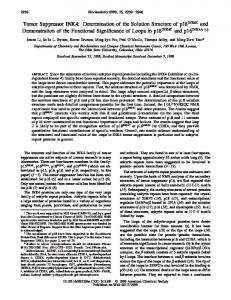
What Power Processing Capability is Required of the Bus Converter? To determine what power processing capability is required of the bus converter two items need to be considered. The first item is all power losses between the output terminals of the bus converter and the points of load. The second item is the available output power of the bus converter as a function of its output voltage. When estimating the power losses between the bus converter’s output terminals and the point of load it is important to consider both the efficiencies of the niPOLs and the impedance of the distribution bus. As an illustration of this point, for a 500W bus converter to power five 100W niPOLs, the niPOLs must be 100% efficient and the distribution bus must have zero impedance; such prerequisites are unrealistic, therefore exercise due diligence. Vicor bus converters have both a max output power rating and a max output current rating. Neither of these specifications should be exceeded; to meet both constraints the output power must be derated as a function of output voltage, POUT/VOUT ≤ IMAX, as shown in Figure 2. This is particularly important to keep in mind since niPOLs behave as constant power devices. If a single IBC or BCM module does not have enough power processing capability for your application, consider paralleling multiple bus converters. For more details on how to configure Vicor bus converters in an array please consult the data sheets, our applications engineers and AN:016 – Using BCM Bus Converters in High Power Arrays.
AN:001
Page 2
Figure 2 Vicor Bus Converter Output Power vs. Input Voltage
Output Power (POUT)
Rated Power
POUT (Max.) POUT = IMAX VOUT
Safe Operating Area Output Voltage (VOUT) VIN (Min.) Low Line
VIN (Max.) High Line
Are Heat Sinks Required? Are Fans Required? VI Brick® IBCs are very efficient, open frame converters. Certain model IBCs achieve peak efficiencies greater than 98%. This high efficiency eliminates the need for heat sinking in the majority of applications. However, a fan cooling the IBC with at least 200LFM is recommended. For further thermal data regarding the IBC please consult the individual data sheet. VI Chip® BCM® modules are manufactured in a pick-and-place compatible package, designed for high volume manufacturing. This package also provides a low case to junction thermal impedance and a flat surface onto which heat sinks can be mounted. For further information regarding the thermal management of BCM modules please consult AN:008 – VI Chip Bus Converter Module (BCM) Thermal Management. VI Brick BCM modules are manufactured in a baseplate equipped package optimized for conduction cooled applications, especially when mounting onto a cold-plate. These products provide a rugged design and simplified mounting to reduce design time and thermal management costs.
External EMI Filter Considerations IBC and BCM modules have a switching frequency often exceeding 1MHz, which is higher than that of most competitive products, enabling the design of more compact EMI filters. For information on how to design a filter for BCM modules please refer to AN:006 – A Filter Solution for the BCM. For further information regarding filter design for IBCs please consult with your local Vicor applications engineer. The IBC conforms to industry standard eighth-brick and quarter-brick pinouts, and so it can be used as a drop in replacement for most competitor products. However, given the high switching frequency of the IBC, the onboard EMI filter may need to be altered. Keep in mind that a filter designed to attenuate 100kHz EMI may be self-resonant at frequencies well within the EMI spectra of the IBC. Often the filter may be reduced in size enabling superior performance of the IBC. Consult with Applications Engineering for assistance with your particular application if necessary.
AN:001
Page 3
Input Bus Damping The wide bandwidth of Vicor bus converters enables them to very quickly process power as needed by the downstream niPOLs. It also guarantees that any voltage deviations present at the input of the bus converter will most certainly also appear at the output multiplied by its K factor. That includes any resonances, which may become amplified by the negative AC resistance presented by the niPOLs. A distribution inductance greater than 100nH may resonate with the input capacitance of the bus converter at sufficiently low enough frequency to create an oscillation. To mitigate this potential instability it is important to minimize distribution inductance and ensure a critically damped response. Even if the negative resistance presented by the niPOLs does not come into play, an under-damped input bus is vulnerable to being excited by input reflected ripple currents. For distribution inductance greater than 100nH a RC damper directly at the input is recommended to critically dampen the input terminals. For example, for 200nH of distribution inductance, 47µF in series with 0.3Ω connected across the input terminals will suffice. An electrolytic capacitor could be substituted provided that the ESR, ESL and temperature dependence are carefully considered.
Source Impedance of Input Bus Given the high power processing capability of the bus converter it is very important to minimize the source impedance to lessen the voltage drop at its input terminals when the bus converter is processing high power. This is particularly important when operating near low line. As a rule of thumb the source impedance should be at worst 10% of the lowest possible bus converter input impedance. For example, a bus converter processing 500W has a input impedance of (48V) 2 / 500W = 4.6Ω, in which case the source impedance should at worst be 0.46Ω from DC to about 5MHz. The input of the bus converter can be bypassed with additional capacitance to compensate for the source’s inability to guarantee low source impedance at higher frequencies.
Max Output Capacitance of Intermediate Bus The total capacitance at the output of the bus converter should not exceed the max output capacitance specified in the data sheet. Remember to include the input capacitance internal to the niPOLs when budgeting for additional capacitance to be placed at the output of the bus converter. Both the IBC and BCM® modules offer very low AC impedance beyond the bandwidth of most niPOLs. As long as the distribution impedance is also low, consider moving capacitance required at the input of the niPOLs to the input of the bus converter. Doing this reduces the size of capacitance used since a capacitance on the intermediate bus is equivalent to that capacitance divided by the square of the K factor when reflected to the input bus. For example, with a K factor of 1/5 a mere 4µF on the input bus looks like 100µF on the intermediate bus.
Input Line Fusing Both the IBC and BCM modules are not internally fused in order to provide flexibility in configuring power systems. However, input line fusing must always be incorporated within the power system A fast acting fuse should be placed in series with the +IN port. For more information or to discuss your specific application contact Vicor Applications Engineering: Contact Us: http://www.vicorpower.com/contact-us.
AN:001
Page 4
Limitation of Warranties Information in this document is believed to be accurate and reliable. HOWEVER, THIS INFORMATION IS PROVIDED “AS IS” AND WITHOUT ANY WARRANTIES, EXPRESSED OR IMPLIED, AS TO THE ACCURACY OR COMPLETENESS OF SUCH INFORMATION. VICOR SHALL HAVE NO LIABILITY FOR THE CONSEQUENCES OF USE OF SUCH INFORMATION. IN NO EVENT SHALL VICOR BE LIABLE FOR ANY INDIRECT, INCIDENTAL, PUNITIVE, SPECIAL OR CONSEQUENTIAL DAMAGES (INCLUDING, WITHOUT LIMITATION, LOST PROFITS OR SAVINGS, BUSINESS INTERRUPTION, COSTS RELATED TO THE REMOVAL OR REPLACEMENT OF ANY PRODUCTS OR REWORK CHARGES). Vicor reserves the right to make changes to information published in this document, at any time and without notice. You should verify that this document and information is current. This document supersedes and replaces all prior versions of this publication. All guidance and content herein are for illustrative purposes only. Vicor makes no representation or warranty that the products and/or services described herein will be suitable for the specified use without further testing or modification. You are responsible for the design and operation of your applications and products using Vicor products, and Vicor accepts no liability for any assistance with applications or customer product design. It is your sole responsibility to determine whether the Vicor product is suitable and fit for your applications and products, and to implement adequate design, testing and operating safeguards for your planned application(s) and use(s). VICOR PRODUCTS ARE NOT DESIGNED, AUTHORIZED OR WARRANTED FOR USE IN LIFE SUPPORT, LIFE-CRITICAL OR SAFETY-CRITICAL SYSTEMS OR EQUIPMENT. VICOR PRODUCTS ARE NOT CERTIFIED TO MEET ISO 13485 FOR USE IN MEDICAL EQUIPMENT NOR ISO/TS16949 FOR USE IN AUTOMOTIVE APPLICATIONS OR OTHER SIMILAR MEDICAL AND AUTOMOTIVE STANDARDS. VICOR DISCLAIMS ANY AND ALL LIABILITY FOR INCLUSION AND/OR USE OF VICOR PRODUCTS IN SUCH EQUIPMENT OR APPLICATIONS AND THEREFORE SUCH INCLUSION AND/OR USE IS AT YOUR OWN RISK.
Terms of Sale The purchase and sale of Vicor products is subject to the Vicor Corporation Terms and Conditions of Sale which are available at: (http://www.vicorpower.com/termsconditionswarranty)
Export Control This document as well as the item(s) described herein may be subject to export control regulations. Export may require a prior authorization from U.S. export authorities.
Contact Us: http://www.vicorpower.com/contact-us Vicor Corporation 25 Frontage Road Andover, MA, USA 01810 Tel: 800-735-6200 Fax: 978-475-6715
www.vicorpower.com email Customer Service:
[email protected] Technical Support:
[email protected]
©2017 Vicor Corporation. All rights reserved. The Vicor name is a registered trademark of Vicor Corporation. All other trademarks, product names, logos and brands are property of their respective owners.
08/17
Rev 1.5
Page 5