Dec 24, 2013 - We define a multilink, and we represent it with m, as the set of links ..... m pkm where pkm is the degree distribution of the mul- tidegree km.
Percolation in Multiplex Networks with Overlap Davide Cellai1 , Eduardo L´ opez2,3 , Jie Zhou1 , James P. Gleeson1 and Ginestra Bianconi4
arXiv:1307.6359v3 [cond-mat.stat-mech] 24 Dec 2013
2
1 MACSI, Department of Mathematics and Statistics, University of Limerick, Ireland CABDyN Complexity Centre, Sa¨ıd Business School, University of Oxford, Oxford OX1 1HP, UK 3 Physics Department, Claredon Laboratory, University of Oxford, Oxford OX1 3PU, UK 4 School of Mathematical Sciences, Queen Mary University of London, London, E1 4NS, UK
From transportation networks to complex infrastructures, and to social and communication networks, a large variety of systems can be described in terms of multiplexes formed by a set of nodes interacting through different networks (layers). Multiplexes may display an increased fragility with respect to the single layers that constitute them. However, so far the overlap of the links in different layers has been mostly neglected, despite the fact that it is an ubiquitous phenomenon in most multiplexes. Here we show that the overlap among layers can improve the robustness of interdependent multiplex systems and change the critical behavior of the percolation phase transition in a complex way. PACS numbers: 89.75.Fb, 64.60.aq, 05.70.Fh, 64.60.ah
I.
INTRODUCTION
In the last decade we have gained a deep understanding of the interplay between the topology of single complex networks [1–3] and the behavior of critical phenomena occurring on them [4, 5]. Recently, it has become clear that in order to fully investigate the properties of a large variety of complex systems such as energy supply networks [6], complex infrastructures [7–11], social networks [12], climatic systems [13] and brain networks [14], it is necessary to consider their multilayer structure [15]. Each layer corresponds to a network with a specific function, but the entire complex system requires multiple layers operating in a coupled way and forming an interacting set of networks. For example, analyses of the disruptions provoked by an earthquake to large infrastructures show the relevance of interdependence among power transmission and telecommunications [16] and the different resilience of coupled networks such as the power grid and the water system [17]. An important and ubiquitous example of multilayer networks is a multiplex where the same nodes are linked by different networks (layers). A multiplex is formed by a set of N nodes and M layers. Every node is represented in every layer, and every layer is formed by a network of interactions (links) between the nodes. For instance, multiplexes are good descriptions of social networks, where the nodes represent agents and the different layers correspond either to different types of interaction (such as family, work or friendship ties)[12] or to different means of communication (email, chat, mobile phone, etc.. . . ) [18]. Other examples of multiplexes can be found in transportation networks, where cities can be connected by roads, railways, waterways or airline connections [10, 11, 19], or brain networks where different regions of the brain belong at the same time to the functional network of brain activity and to the structural brain network [14]. In the last years, interest on multiplexes has been growing both on the theoretical side, and on the empirical
side of multiplex data analysis. In fact different models of multiplex structure have been formulated [20–23], critical phenomena and dynamical processes have been characterized on multiplex structures [6, 24–40], and finally new structural measures have been introduced and evaluated in large multiplex datasets [10–13]. The theoretical interest has been partly sparked by the discovery [6, 24–26] that the robustness properties of a multiplex formed by interdependent networks is strongly affected by its multilayer structure. In fact a multiplex can be much more fragile than single networks and its functionality can be affected significantly by cascades of node failures [6, 24, 26]. In this context, the mutually connected giant component (MCGC) plays a pivotal role. The MCGC of a multiplex is the extensive component where every pair of nodes is connected in every layer by at least one path formed by nodes inside the MCGC. If a fraction 1 − p of nodes is removed from a multiplex with a MCGC, the size of the MCGC is reduced. At some value of p, a critical point is reached where a first order hybrid transition is observed and the MCGC abruptly drops from a finite value to zero [6, 24–26, 30–32]. Despite the interesting theoretical behavior, analysis of the empirical side offers another observation not yet addressed by the theory, which is that many multiplexes [11, 12, 27] are formed by correlated networks characterized by a significant overlap of the links. For example, in social networks it is common for two friends to communicate both via email and via mobile phone, or in transportation networks two cities connected by a main road are likely to be connected also by a railway. Given such empirical findings, the theory of multiplex networks cannot be complete until the effects of link overlap in the multiplex robustness properties (characterized by the MCGC) are understood. Our aim is not to address a specific application, but give instead a general theoretical approach that can include edge overlap in the study of percolation under random damage. Percolation is perhaps the simplest model of robustness and stability, but it constitutes a first step
2 in dealing with more complex models and even dynamical processes occurring on the network. Therefore, introducing a formalism with edge overlap in percolation on multiplex networks should be seen as an important building block of the science of complex networks. In this paper, we apply this formalism to the case of 2 and 3-layer Poisson graphs and calculate the phase diagrams of the models. We show that edge overlap can significantly enhance the robustness properties of the multiplex. We also show that a multiplex formed by more than two layers presents a very rich phase diagram with high order critical points, characterizing the increased complexity of this percolation problem. In Section II we introduce the notation of multiplexes with edge overlap, in Section III we formulate a general framework to characterize the emergence of the MCGC, in Section IV we calculate the phase diagrams of percolation on 2 and 3-layer Poisson graphs and in Section V we draw the conclusion of this work.
i
α=1
i
α=2
i
α=3
l j l j l j
t t t
r r r
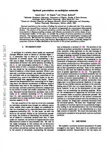
FIG. 1: In this example of multiplex network with three layers and overlap of the links the nodes (i, j) are linked by a multilink m ~ = (1, 1, 0), the nodes (r, l) are linked by a multilink m ~ = (1, 1, 1), all the other pairs of nodes are linked by a multilink m ~ = (0, 0, 0).
i.e. for each m ~ = {0, 1}M , ~ Am ij =
M Y � α � aij mα + (1 − aα ij )(1 − mα ) .
(1)
α=1
II.
MULTIPLEX WITH OVERLAP
Consider a multiplex formed by N labelled nodes i = 1, 2 . . . , N and M layers. We can represent the multiplex as described in [15]. To this end we indicate by G~ = (G 1 , . . . , G α , . . . , G M ) the set of all the networks G α at layer α = 1, 2, . . . , M forming the multiplex. Each of these networks has an adjacency matrix with matrix elements aα ij = 1 if there is a link between node i and node j in layer α and zero otherwise. A useful concept to characterize multiplex structure are multilinks, and multidegrees recently defined in [22]. Let us consider the vector m ~ = (m1 , . . . , mα , . . . , mM ) in which every element mα can take only two values mα = 0, 1. We define a multilink, and we represent it with m, ~ as the set of links connecting a given pair of nodes in the different layers of the multiplex and connecting them in the generic layer α only if mα = 1. Multilinks are mutually exclusive, i.e. any pair of nodes (i, j) can be linked only by one multilink m, ~ that we call m ~ ij . In Figure 1 we show an example of a multiplex where nodes (i, j) are linked by a multilink (1, 1, 0) and nodes (r, l) are linked by a multilink (1, 1, 1). Note how the introduction of the multilink now makes explicit the notion of overlap of the links: the links (i, j) in the layers α1 , . . . , αt overlap if the nodes i and j are ij joined by a multilink m ~ =m ~ ij and mij α1 = · · · = mαt = 1. For a multiplex it is possible to define a set of mul~ tiadjacency matrices of elements by setting Am ij = 1 if ~ node i is linked to node j by a multilink m ~ and Am ij = 0 ~ otherwise. In other words, every element Am ij not only depends on the node pair (i, j) as in classical adjacency matrices, but it is also a function of the generic multilink m. ~ These multiadjacency matrices can be defined in terms of the adjacency matrices (aα ij ) on each layer α,
The expression in the square brackets (in an unweighted network) can only be zero or one. It equals one only when the components of m ~ match the actual presence of an (i, j) link on the layer α. Otherwise, the expression is zero and correctly represents the absence of a multilink of given type m ~ between i and j. The number of multilinks is 2M but the elements of the multiadjacency matrices are not all independent. In fact they satisfy the relation X ~ Am (2) ij = 1, M m∈{0,1} ~
where the sum is over the set of all possible multilinks. ~ Since the elements of the multiadjacency matrices Am ij are either zero or one, the condition given by Eq.(2) implies that between any pair of nodes (i, j) there is a single multilink that we indicate with m ~ ij . Therefore only 2M − 1 adjacency matrices are independent. In most multiplex networks the number of layers is finite, therefore the exponential number of multilinks is not an important limitation to this approach. Moreover, our framework can be easily generalized to the case of multiplexes with a large number of layers M in which only few types of multilinks are allowed. Finally, we define the multidegree with respect to m ~ ~ of a node i, kim , as the total number of multilinks m ~ connected to node i, i.e. ~ kim =
N X
~ Am ij .
(3)
j=1 (1,1)
In the specific case = P of a duplex (M = 2) we have ki oi , where oi = j a1ij a2ij is the local overlap of node i, i.e. the total number of nodes j linked to node i both in layer 1 and in layer 2. In general, for a multiplex of
3 ~ M layers the multidegree k m can be considered as a high P order measure of local overlap as long as α mα > 0. This framework encapsulates two particular cases, which are already known to the scientific community. First, let us consider the case of fully overlapping multiplexes, where all links are the same in all layers. In this case, we recover classical percolation with a continuous second order phase transition. Second, we may consider the case where edges on different layers are totally uncorrelated. As we are considering configuration model graphs on each layer, the multiplex consists of a random coupling of locally tree-like, sparse random graphs [33]. Therefore, the probability of edge overlap vanishes as N → ∞. It has been recently shown that in this case the phase transition is discontinuous [30]. In general, instead, one needs to consider overlap effects when designing or studying the fragility of multiplexes. Our formalism, and in particular the concept of multilink, can be very helpful, giving us a fully controllable tool to study the problem.
that the node i is in the mutually connected giant component. The value of σi is determined by the “messages” that the neighboring nodes send to node i. We denote m ~ ij these “messages” as σj→i . The value of the message is m ~ ij set to one σj→i = 1 if and only if the following two conditions are satisfied: (a) node j is a neighbor of nodePi with a multilink m ~ ij ij connecting them such that α mα > 0; (b) node j belongs to the mutually connected giant component even if the multilink m ~ ij between node j and node i is removed from the multiplex. ij
m ~ Otherwise we will have σj→i = 0. m ~ ij In a locally tree-like multiplex the value of σi and σj→i satisfy the following message-passing relations M Y Y m ~ ij 1 − σi = si (1 − σj→i ) , (4) α=1
III. EMERGENCE OF THE MUTUALLY CONNECTED GIANT COMPONENT (MCGC)
ij
m ~ σj→i = sj
M Y α=1
As we mention in the introduction, the MCGC of a multiplex is the extensive component where every pair of nodes is connected in every layer by at least one path formed by nodes inside the MCGC. Then, we can consider the behavior of the size of the MCGC in a multiplex as a fraction 1 − p of nodes is removed. If there is no link overlap, at a critical value of p, a first order hybrid transition is observed and the MCGC abruptly drops from a finite value to zero [6, 24–26, 30, 31]. Our goal is to characterize the effect of link overlap on how the mutually connected giant component (MCGC) changes as a function of p (the fraction of remaining nodes). Specifically, we will follow and extend the approach developed by Son et al. [31] for studying the percolation on two interdependent networks without overlap. First of all, we observe that a node i belongs to the mutually connected giant component of the multiplex networks if and only if the following M conditions are met simultaneously: for every layer α = 1, 2, . . . , M at least one of the neighbor nodes of i in network α belongs to the mutually connected giant component of the interdependent networks. We consider a tree-like multiplex, i.e. a multiplex in which the combined network of all the P layers (i.e. the network of adjacency matrix Bij = θ( α=1,M aα ij ), where θ(x) = 1 if x > 0 otherwise θ(x) = 0) is locally tree-like. According to the above recursive definition of the MCGC, on a locally tree-like multiplex we can determine if a node belongs to the MCGC by a message-passing algorithm [32, 41], described in Son et al. as an “epidemic spreading” process [31]. Let si = 0, 1 indicate if a node is removed or not from the network and let σi = 0, 1 be the indicator function
j∈Nα (i)
1 −
Y l∈Nα (j)\i
lj
m ~ (1 − σl→j ) ,
(5)
where Nα (i) indicates the set of nodes that are neighbor of node i in layer α. The expression within square brackets in Eq. (4) is one only if on layer α at least one of the neighbors j of node i is connected to the MCGC by an edge other than the (i, j) edge, otherwise is zero. Equation (5) has been written using the same logic, but taking now into consideration that j is required to be in the MCGC by connecting to a neighbor l which must be different from i. This is calculated by subtracting from one the probability that all the neighbors j of i are not attached to the MCGC. Let us now consider equation (5), by using the formula M Y
(1 − xi ) =
X P (−1) α rα xr11 . . . xrMM ,
α=1
~ r
where ~r = (r1 , P r2 , . . . , rα , . . . rM ) with rα = 0, 1, and where the sum r. We ~ r is over all possible vectors ~ can expand the multiplications and write ij
m ~ σj→i = sj
M X Y P (−1) α rα
Y
α=1 l∈Nα (j)\i
~ r
lj
m ~ (1 − σl→j )rα . (6)
By observing that for each node l neighboring node j in layer α we should necessarily have mlj α = 1 and that m ~ lj σl→j = 0, 1, it is possible to swap the two products in equation (6) and show that ij
m ~ σj→i = sj
X ~ r
(−1)
P
α
rα
N Y P lj m ~ lj (1 − σl→j ) α rα mα . l=1 l6=i
(7)
4 Similarly, we can show that N Y X P P li rα m ~ li α σi = si (−1) (1 − σl→i ) α rα m α .
(8)
l=1
~ r
Let us now consider a multiplex belonging to the multiplex ensemble [22] characterized by a given multidegree distribution and no degree-degree (multidegreemultidegree) correlations. We can construct a network in this ensemble by extending the configuration model to networks with multidegrees. To this end, we draw the ~ multidegree sequence {kim } from a multidegree distribum ~ ~ tion PP({k }). We then attach kim stubs of type m ~ such that α mα > 0 to each node i. Finally we randomly match the stubs of the same type of multilinks belonging ~ to different nodes. In this ensemble the probability P (G) of a multiplex G~ is given by A~0ij m ~ !Aij m ~ m ~ ~ m ~ X Y Y kim ki kj kj ~ = 1 − (9) P (G) m ~ iN m ~ iN hk hk ij m6 ~ =~ 0
m6 ~ =~ 0
~ where we have assumed that the multidegrees kim < q
m �
� m ~ ~ ki N , ∀m ~ 6= ~0, and we have indicated with ki the average of the multidegrees m ~ present in the network. The condition on the multidegrees imposes a “multidegree structural cutoff” that ensure the fact that in the multiplex the multidegrees of linked nodes are not correlated. We assume that the nodes are removed with probability (1 − p), and that therefore the sequence {si } indicating if the node i is removed (si = 0) or not (si = 1) has probability
P ({si }) =
N Y i=1
[psi + (1 − p)(1 − si )] .
(10)
We define P S~n the probability that following a multilink ~n (with α nα > 0) we reach a node in the MCGC ~ n in a multiplex in this ensemble. Since σj→i = 0, 1 the probability S~n that a random message in the multiplex m ~ ij is equal to one, i.e. S~n = P (σj→i = 1|m ~ ij = ~n) is equal to the average
� m ~ ij S~n = δ(m ~ ij , ~n)σj→i (11) where δ(m ~ ij , ~n) = 1 if m ~ ij = ~n and δ(m ~ ij , ~n) = 0 otherwise, and where we use the notation hδ(m ~ ij , ~n)f
=
ij
(m ~ ij )i
P ~ P ~ P (G) {si } P ({si }) i,j G
P
ij
= δ(m ~ ij ,~ n)fij (m ~ ij ) P . ~ i0 j 0 ,~ n) i0 ,j 0 δ(m
(12)
for any function fij (m ~ ). The equation for S~n can be derived from the recursive Eq. (7) as follows
m � ~ ij δ(m S ~n = σj→i ~ ij , ~n) (13) * + N X Y P P lj lj m ~ r r m ij α α α = δ(m ~ , ~n) sj (−1) α (1 − σl→j ) α . ~ r
l=1 l6=i
The probability that a random multilink ~n = m ~ ij of the network will have a node at its end (node j) with
mul� ~ ~ tidegree sequence {k m } is given by k~n P ({k m })/ k~n . If ~ the node j has multidegrees k m , it will have a number m ~ k of incoming messages from multilinks m. ~ When calculating the average in Eq.(13) we have to consider all m ~ lj the messages σl→j incoming to node j except the mes~ n sage coming from node i that is given by σi→j , i.e., it is of type ~n. Therefore, since on a tree-like network the messages sent by any two neighbors will be independent, we have that Eq. (13) becomes S~n = p
X k~n X P ~ (−1) α rα × P ({k m }) ~ n hk i m ~ ~ r
{k }
×
Y m| ~
P
α
mα rα >0
~ D Ekm −δ(m,~ ~ n) lj m ~ lj (1 − σl→j )δ(m, ~ m ~ ) ,
(14) ~ where P P ({k m }) is the sum is over all ~ r (r1 , r2 , . . . , rα , . . . , rM ). Sm ~ given in Eq. (11) we
multidegree distribution, the the possible vectors ~r = Finally using the definition of obtain,
X X k~n PM m ~ α=1 rα × P ({k }) (−1) hk~n i m ~ ~ r {k } Y ~ km −δ(m,~ ~ n) (1 − Sm , (15) × ~)
S~n = p
m| ~
P
α
mα rα >0
where we have used the same notation as in Eq. (14). Similarly, the probability S = P (σi = 1) that a random node belongs to the MCGC can be expressed as X X X σi ~ S = P (G) P ({si }) . (16) N i {si }
~ G
Starting from Eq. (8) and using similar steps used to derive Eq. (15), it can be shown that S must satisfy the following equation X X PM ~ S = p P ({k m }) (−1) α=1 rα × ~ } {km
×
~ r
Y m| ~
P
α
m ~
k (1 − Sm , ~)
(17)
mα rα >0
where we have used the same notation as in Eq. (14). We note here that the Eqs. (17) − (15) are generalizations of Eq. (8) in [25], when the overlap of the links is significant. Moreover we observe that here, as in other percolation problems [32], the quantities S~n and S are self-averaging, i.e., we expect that the network average of the messages and the values of σi converge, in the large network limit, to S~n and S respectively. An interesting case emerges when the degree distribu~ tion of the multidegrees is factorizable, i.e. P ({k m }) =
5 Q
~ is the degree distribution of the mul~ where pk m m ~ pk m ~ tidegree k m . In this case we can introduce the following generating functions of the real (scalar) variable zm ~: X ~ km 0 pkm Gm ~ zm ~) = ~ ~ (zm
(18)
0.5
k
I
Therefore Eqs. (17) and (15) now read X X Y PM 0 (−1) α=1 rα Gm S=p ~ ) (19) ~ (1 − Sm ~ } ~ r {km
X X PM �f (~n,~r) � × (−1) α=1 rα G~n1 (1 − S~n ) Y m ~ α mα rα >0 m6 ~ =~ n
0 Gm ~) ~ (1 − Sm
(20)
P
where f (~n, ~r) = 1 if wise. IV. A.
P
α rα nα
0
1
2
3
c1 p
m ~ α mα rα >0
~ } ~ r {km
×
0.0
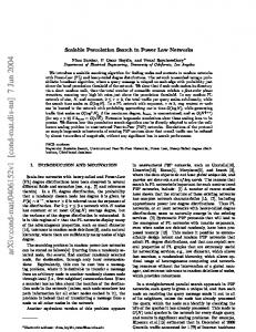
FIG. 2: (Color online) Phase diagram of the two layer multiplex with Poisson degree distribution in each layer. In region I there is no percolation, in region II the system supports a MCGC. The solid red line indicates the points of hybrid first order phase transitions, the dashed black line indicates the line of second order phase transitions. T is the tricritical point.
> 0 and f (~n, ~r) = 0 other-
0.4
SPECIFIC EXAMPLES
Two Poisson layers with Overlap
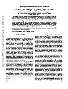
We consider now the case of a duplex M = 2 in which the multi-degree distributions are Poisson with means governed by the real parameters c1 and c2 (note that, here and in the following, 1 and 2 in c1 and c2 are indices, not exponents). So we assume: hk 11 i = c2 , and hk 01 i = hk 10 i = c1 . Due to the properties of the Poisson distribution, from equation (17) we have S = S01 = S10 = S11 , where S satisfies the equation h i 1 2 1 2 S = p 1 − 2e−(c +c )S + e−(2c +c )S . (21) By setting x = S/p, we can study the solutions of the equivalent equation h i 1 2 1 2 h(x) = x − 1 − 2e−(c p+c p)x + e−(2c p+c p)x = 0 (22) in the (c1 p, c2 p) parameter plane. Fig. 2 shows the phase diagram of this model. Here the red solid line indicates a line of hybrid first order phase transition points and the black dashed line indicates a line of second order phase transition points, the point T is a tricritical point. We compare the analytical solutions S(p) with numerical simulations in Fig. 3. There is good agreement where the transition is continuous. In the case of discontinuous transitions and close to the tricritical point, we observe
S
S~n = p
P
II
c2 p
~ km
~ X km ~ km −1 1 Gm pk m . ~ z ~) = ~ (zm m ~ m ~ hk i m ~
T
1.0
0.2
0.0 0.0
0.2 p
0.4
FIG. 3: (Color online) Strength S of the MCGC as a function of p for some values of c2 /c1 (here we only show a zoom of the region where the transitions occur). Continuous lines represent the analytic solution, points indicates simulations over networks of size N . From left to right: c2 /c1 = 4 (green), N = 104 ( ), N = 5 · 104 (�); c2 /c1 = 1.22 (red), N = 104 (4), N = 5 · 104 (5), c2 /c1 = 0.25 (blue), N = 104 (•), N = 5 · 104 (+). From the comparison between the two sizes, it appears that the points converge to the analytical solution when N increases.
finite size effects, with an improved agreement for larger network sizes. The line of continuous phase transitions can be calculated analytically by imposing the condition that a non trivial solution x? > 0, satisfying h(x? ) = 0, goes to zero as a function of the parameter p. Therefore, we expand
6 h(x? ) for x? = � � 1 finding
B.
1 1 h(x? ) = h0 (0)� + h00 (0)�2 + h000 (0)�3 + O(�4 ). (23) 2 3! If h0 (0) < 0 and h00 (0) > 0, we find the following solution x? = � � 1 of Eq. (23) � x? = � ∝ p − 1/c2 , (24) implying S ∝ p − 1/c2
�β
(25)
with β√= 1. This indicates that as long as h00 (0) > 0 (i.e. c2 > 2c1 ) the points c2 p = 1 for which h0 (0) = 0 are second order critical points. √ At the point c2 /c1 = 2, c2 p = 1, we have h00 (0) = 0. To find a non trivial solution of Eq. (23) for p ' pc = 1/c2 (in the following, we will use pc as the generic critical value of p at a phase transition), we have to go up to the third order in the � expansion, finding, since h000 (0) > 0, x? = � ∝ p − 1/c2
�1/2
,
(26)
implying S ∝ p − 1/c2
�β
(27)
√ with β = 1/2. Therefore the point c2√ /c1 = 2, c2 p = 1 is the tricritical point T . For c2 < 2c1 and c2 p < 1 we observe a line of first order phase transition points determined by the conditions h(x? ) = h0 (x? ) = 0 with x? > 0. The expansion of Eq. (21) at these transition points shows that β = 1/2, thus the transition is hybrid. Finally, we observe that in the case c2 = 0 we have c1 pc = 2.4554 . . . recovering the result of two Poisson networks without overlap and with average degree c1 [6]. From this simple model we observe several interesting features. First, we observe that increasing the overlap c2 between the layers improves the robustness of the multiplex system and changes the order of the percolation phase transition from first order to second order in a smooth way (through a tricritical point). Moreover, the continuous phase transition is entirely driven by the (classical) percolation of the sub-network of double edges (c2 p = 1). Finally, it is interesting to note that when the ratio c1 /c2 is large enough, the percolating phase extends in a region where it can be c2 p < 1 (Fig. 2). This is not surprising, as it signals that the small overlap behavior takes over the overlap-driven percolating phase. In other words, on the right hand side of the tricritical point T in Fig. 2, the MCGC is not simply containing a classical giant cluster entirely constituted by double edges, as this does not percolate on its own if c2 p < 1. Instead, a relevant fraction of pairs of nodes in the MCGC are connected by non-coincident paths of each type of edges. This is the scenario described, in the case of negligible edge overlap, in [30].
Three Poisson Layers with Overlap
As a second example, we consider the ensemble of a three layer multiplex (M = 3) with Poisson multi-degree distribution and hk 100 i = hk 001 i = hk 010 i = c1 , hk 110 i = hk 101 i = hk 011 i = c2 and hk 111 i = c3 (recall that 1, 2, 3 in c1 , c2 , c3 are, as earlier, indices, not exponents). As in the previous case, we have just one order parameter S = Sm ~ that satisfies the equation h 1 2 3 S = p 1 − 3e−(c +2c +c )S i 1 2 3 1 2 3 + 3e−(2c +3c +c )S − e−(3c +3c +c )S . (28) By setting x = S/p, we can define a function g(x) as g(x) = x − [1 − 3e−(c −e−(3c
1
1
p+2c2 p+c3 p)x
p+3c2 p+c3 p)x
],
1
+ 3e−(2c
p+3c2 p+c3 p)x
(29)
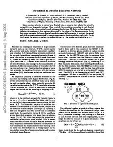
and we can recast the equation for S as g(x? ) = 0. The 3D phase diagram is displayed in Fig. 4 for c3 p < 1. Under the surface there is no percolation (S = 0), whereas above the surface we have S > 0. The blue surface at c3 p = 1 corresponds to continuous transitions, the pink surface at c3 p < 1 represents discontinuous transitions.
FIG. 4: (Color online) The phase diagram of the three layer multiplex with Poisson multidegree distribution parametrized by c1 , c2 , c3 . Below the plotted surface we have S = 0, above the surface we have S > 0.
Fig. 5 displays a section of the same phase diagram at c3 p = 1. This section is quite relevant, as it entirely contains the line of tricritical points, plotted as a dot-dashed blue line. This√line starts at point U given by c1 p = 0, c2 p = 1/ 6, c3 p = 1 and terminates at a multicritical point Q determined by the conditions g(0) = g 0 (0) = g 00 (0) = g 000 (0) = 0 given by c1Q p = 0.892550, c2Q p = 0.158562, c3Q p = 1 (see Appendix for further details). The tricritical line is determined by 0 00 the condition g(0) = 0 and is given by p= g (0) = g (0) 1 2 1 1 2 c p = 6 [−3c p + 6 + 9(c p) ], c3 p = 1, with c1 p < c1Q p.
7 At c1 p > c1Q p, the nature of the transition changes, as the relatively higher fraction of single edges drives the system into a behavior where the MCGC is mainly characterized by nodes connected by different paths on each layer (as in the case of non overlapping layers [30]). Therefore, the solid red line beyond point Q represents the locus of points characterized by a discontinuous phase transition of the percolating phase into a critical S = 0 phase. U
0.4
c2 p
T
0.2
II
Q I
0.0
E 0
1 c1 p
2
FIG. 5: (Color online) Section of the phase diagram of the three layer multiplex with Poisson multidegree distribution at c3 p = 1. A line of tricritical points (dot-dashed blue) encounters the line of discontinuous phase transitions (solid red) at the multicritical point Q.
To further characterize these critical phenomena, it is also interesting to examine sections at fixed c2 p (Fig. 6), which essentially governs the fraction of double edges in the multiplex network. We can identify three characteristic topologies as c2 p varies, exemplified by the lines (1), (2) and (3) of Fig. 6. The two discriminating cases are characterized by (i) the multicritical point Q, and (ii) the end point U . At small values of c2 p, the MCGC can collapse either continuously or discontinuously, depending on the relative abundance of single and triple edges. If c3 /c1 is smaller than the slope of the segment OE, random damage causes a discontinuous transition, whereas along the c1 p = 0 line, for example, we recover the continuous phase transition of classical percolation as the three Poisson networks are coincident. The line of second order critical points (dashed black) is determined by the condition g(0) = g 0 (0) = 0, which implies c3 p = 1. Similarly to the two layer case, the continuous transition constitutes the classical percolation scenario and is entirely driven by the subnetwork of triple edges. This line ends as it encounters the line of discontinuous transitions at a point which depends on the value of c2 p. Quite interestingly, the line of first order hybrid transitions extends into the region c3 p > 1 and ends in a critical point C defined by g(x? ) = g 0 (x? ) = g 00 (x? ) = 0 with x? > 0. Indeed there
is a region of phase space such that if we fix c1 , c2 and c3 and we raise the value of p, we first cross a second order transition point as S continuously grows to a small finite value, then we cross an additional discontinuous phase transition and S jumps from a small finite value to a larger value. This discontinuous transition separates a percolating phase (driven by nodes connected by non-coincident paths) from a classical percolating phase (driven by coincident paths formed by triple edges). In the second characteristic topology, occurring for c2U < c2 < c2Q , the critical line and the line of discontinuous transitions match at a tricritical point T . The line of tricritical points ends at the multicritical point Q. The second order critical √ line, instead, disappears at the point U . For c2 p > 1/ 6, the third topology is only characterized by a line of discontinuous transitions driven by the low overlap behavior (line (3)). In Fig. 7, we plot the behavior of the function g(x) at the points U , Q and one of the critical points C of the phase diagram. As is customary in the analysis of critical phenomena, the exponent β determines the critical behavior of S in the vicinity of a phase transition occurring at a critical occupation probability pc : S − Sc ∝ (p − pc )β as p → pc . The values of β can be calculated at every critical point by an appropriate expansion of the equation (28), as explained in detail in the Appendix. We find β = 1 at the second order transition points, β = 1/2 at the tricritical points, β = 1/3 at the multicritical point Q and β = 1/3 at the critical points C. This implies that the critical points C are in the same universality class as the critical points observed in heterogeneous k-core percolation on Poisson networks [28, 29]. As in the two layer case, this phase diagram shows that the multiplex becomes more resilient by increasing the fraction of triple edges. However, it also shows that by raising the ratio c2 /c1 the phase transition may become discontinuous. For example, if we consider Fig. 6, it emerges that at fixed c1 p one may encounter a discontinuous transition by varying the parameter c3 p. This occurs if the relative fraction of double edges c2 p is large enough. This suggests that network design must take into consideration all the relevant layers, otherwise network failure might evolve towards a catastrophic regime.
V.
CONCLUSIONS
In this paper we have presented a general framework for studying the emergence of a MCGC in multiplex network with overlap. We show that the presence of a critical value of edge overlap in a duplex can both change the order of the phase transition from hybrid first order to second order, and improve the robustness of the system. We also show that in multiplexes with more than two layers the observed critical phenomena become remarkably complex, including the presence of high order
8
Q
U T
E
II
c3 p
1.0
C
0.5 (3)
(2)
(1)
I
0.0
O
0
1
2
3
1
c p FIG. 6: (Color online) Phase diagram of the three layer multiplex with Poisson multidegree distribution at fixed c2 p. The dashed black line is the line of second order transitions (classical percolation). The red full lines represent first order hybrid transitions at different values of c2 p. Lines (1-3) refer to c2 p = 0, 0.3 and 0.8, respectively.
multicritical points. On one hand, there may occur first order phase transitions between percolating phases with different strengths. On the other, it emerges that overlap of edges which do not involve all the layers can also change a continuous phase transition to a discontinuous one, making system reliability less predictable. This is a feature which may be relevant in the design of large scale infrastructures. Here we stress that in real multiplexes— such as in online games [12], social networks [40] and epidemiology [37]—the presence of link overlap is the norm rather than the exception. Therefore, this work represents an important step for characterizing the robustness properties of real multiplexes, and it is also likely to have an impact on the dynamic processes occurring on multiplex systems. Note: During the evaluation of this manuscript, we came to know about two papers where percolation on 2-layer Poisson graphs with overlap is studied [42, 43]. D. C., J. Z. and J. G. acknowledge funding from Science Foundation Ireland (11/PI/1026) and the FETProactive project PLEXMATH and E. L. acknowledges funding from James Martin 21st Century Foundation Reference no: LC1213-006.
0.003 Appendix A: Calculation of the critical points in the three layer Poisson multiplex
g(x)
U Q
C
0.000 −0.001 0.0
0.2 x
0.4
FIG. 7: (Color online) Behavior of the function g(x) at the points U , Q, C and E. The point Q is characterized by the conditions g(0) = g 0 (0) = g 00 (0) = g 000 (0) = 0. The points C are characterized by the conditions g(x? ) = g 0 (x? ) = g 00 (x? ) = 0 with x? > 0.
We now calculate the critical points and exponents of the 3-layer Poisson multiplex with hk 100 i = hk 001 i = hk 010 i = c1 , hk 110 i = hk 101 i = hk 011 i = c2 and hk 111 i = c3 . Let x? > 0 be a solution of equation g(x) = 0 where the function g is defined in (29). In order to calculate the position of a continuous phase transition we expand g(x? ) for x? = � � 1 finding 1 g(x? ) = g 0 (0)� + g 00 (0)�2 + 2 1 1 + g 000 (0)�3 + g 0000 (0)�4 + O(�5 ), (A1) 3! 4! with
g 0 (0) g 00 (0) g 000 (0) g 0000 (0)
= = = =
1 − c3 p 3(c1 p + c2 p + c3 p)2 − 3(2c1 p + 3c2 p + c3 p)2 − (3c1 p + 3c2 p + c3 p)2 −3(c1 p + c2 p + c3 p)3 + 3(2c1 p + 3c2 p + c3 p)3 − (3c1 p + 3c2 p + c3 p)3 3(c1 p + c2 p + c3 p)4 − 3(2c1 p + 3c2 p + c3 p)4 − (3c1 p + 3c2 p + c3 p)4 .
The set of second order critical points are determined by the condition g 0 (0) = 0 and g 00 (0) > 0 with the additional condition that a first order phase transition has not already occurred in the multiplex. These conditions imply
(A2)
c3 p = 1 and determine all the points in region I of Fig. 6 in the main text. Close to these transition points, for p ' pc = 1/c3 , we have g 00 (0) > 0 therefore, by using the
9 expansion of g(x) given by Eq. (A1) we get � x? = � ∝ p − 1/c3 ,
(A3)
implying S ∝ p − 1/c3
�β
(A4)
with β = 1. The line of tricritical points is determined by the conditions g 0 (0) = g 00 (0) = 0 and g 000 (0) > 0 yielding √ �1/3 √ �1/3 + 3+2 2 3+ 3−2 2 c p < 6 i p 1h 2 1 c p = −3c p + 6 + 9(c1 p)2 6 c3 p = 1.
with β = 1/3. Regarding the critical points C occurring at xc > 0, we have the conditions g(xc ) = g 0 (xc ) = g 00 (xc ) = 0. Let us define the following auxiliary function Φ(y 1 , y 2 , y 3 ) (as throughout the paper, α is a layer index, not an exponent, in variable y α ): Φ(y 1 , y 2 , y 3 ) = 1 − 3e−(y
1
+2y 2 +y 3 )
1
2
+ 3e−(2y
1
+3y 2 +y 3 )
3
−e−(3y +3y +y ) . (A11) Using function Φ, we can rewrite g(x) and its derivatives in the following way:
1
(A5)
Close to these transition points, for p ' pc = 1/c3 , we have g 000 (0) > 0 therefore, by using the expansion of g(x) given by Eq. (A1) we get x? = � ∝ p − 1/c3
�1/2
,
�β
(A7)
,
X
�β
(A10)
X ij
X i
+
2
ij
ij
∂2Φ . ∂y i ∂y j
(A13)
(A14)
ci cj
(A15)
1 ∂Φ = ∂y i pc
(A16)
∂2Φ =0 ∂y i ∂y j
(A17)
Now let us expand equation (A12) by imposing S = Sc +ξ for ξ → 0 and p = pc + δ for δ → 0. Substituting the expansion of Φ
Φ(c1 (Sc + ξ), c2 (Sc + ξ), c3 (Sc + ξ)) = Φ(c1 Sc , c2 Sc , c3 Sc ) + 1X
ci
i
(A9)
implying S ∝ p − 1/c3
ci cj
i
∂Φ ∂y i
Sc = Φ(c1 Sc , c2 Sc , c3 Sc ) pc
Close to this transition point, for p ' pc = 1/c3 , we have g 0000 (0) > 0. Therefore, by using the expansion of g(x) given by Eq. (A1), we get x = � ∝ p − 1/c
X
ci
So, the conditions g(xc ) = g 0 (xc ) = g 00 (xc ) = 0 defining a point C imply:
√ �1/3 √ �1/3 3+ 3−2 2 + 3+2 2 c1 = = 0.89255... c3 6 √ �1/3 √ �1/3 −2 + 4 − 2 2 + 4+2 2 c2 = = 0.158562.... 3 c 6 p = 1/c3 . (A8)
� 3 1/3
X
g 00 (x) = −p2
with β = 1/2. The multicritical point Q is determined by the conditions g 0 (0) = g 00 (0) = g 000 (0) = 0 yielding
?
g 0 (x) = 1 − p
(A6)
implying S ∝ p − 1/c3
S − Φ(c1 S, c2 S, c3 S) p (A12)
g(x) = x − Φ(c1 px, c2 px, c3 px) =
ci cj
ci
∂Φ ξ ∂y i
∂3Φ ∂2Φ 2 1 X i j k cc c ξ + ξ 3 + O(ξ 4 ), (A18) i j i ∂y ∂y 6 ∂y ∂y j ∂y k ijk
10 and applying the conditions above, we get � � ξ Sc 3 4 + + K3 ξ + O(ξ ) . (A19) 0 = Sc + ξ − (pc + δ) pc pc
Hence, we have β = 1/3.
From which it yields ξ ∼ δ 1/3 .
(A20)
[1] R. Albert and A.-L. Barabasi, Reviews of Modern Physics 74, 47 (2002). [2] M. E. J. Newman, SIAM Review 45, 167 (2003). [3] S. Boccaletti, V. Latora, Y. Moreno, M. Chavez and D.U. Hwang, Physics Reports 424, 175 (2006). [4] S. N. Dorogovtsev, A. Goltsev and J. F. F. Mendes, Rev. Mod. Phys. 80, 1275 (2008). [5] A. Barrat, M. Barth´elemy, A. Vespignani Dynamical Processes on complex Networks (Cambridge University Press, Cambridge, 2008). [6] S. V. Buldyrev, R. Parshani, G. Paul, H. E. Stanley and S. Havlin, Nature 464, 1025 (2010). [7] S. M. Rinaldi, J. P. Peerenboom, and T. K. Kelly, IEEE Control Syst. Mag. 21, 11 (2001). [8] M. Kurant and P. Thiran, Phys. Rev. Lett. 96, 138701 (2006). [9] V. Rosato, L. Issacharoff, F. Tiriticco, S. Meloni, S. D. Porcellinis, and R. Setola, International Journal of Critical Infrastructures 4, 63 (2008). [10] R. G. Morris, M. Barth´elemy, Phys. Rev. Lett. 109, 128703 (2012). [11] A. Cardillo, J. G´ omez-Garde˜ nes, M. Zanin, M. Romance, D. Papo, F. del Pozo and S. Boccaletti, Sci. Rep. 3, 1344 (2013). [12] M. Szell, R. Lambiotte, S. Thurner, PNAS, 107, 13636 (2010). [13] J. Doges, H. Schultz, N. Marwan, Y. Zou and J. Kurths, Eur. Phys. J. B 84, 635 (2011). [14] E. Bullmore and O. Sporns, Nat Rev Neurosci 10, 186 (2009). [15] P. J. Mucha, T. Richardson, K. Macon, M. A Porter, J.-P. Onnela, Science, 328,876 (2010). [16] L. Due˜ nas-Osorio and A. Kwasinski, Earthquake Spectra 28, S581 (2012). [17] I. Hernandez-Fajardo and L. Due˜ nas-Osorio, Earthquake Spectra 27, 23 (2011). [18] A. Halu, R. J. Mondragon, P. Panzarasa and G. Bianconi, PLoS ONE 8(10): e78293 (2013). [19] O. Woolley-Meza, C. Thiemann, D. Grady, J. J. Lee, H. Seebens, B. Blasius, and D. Brockmann, The European Physical Journal B - Condensed Matter and Complex Systems 84, 589 (2011). [20] V. Nicosia, G. Bianconi, V. Latora, and M. Barthelemy, Phys. Rev. Lett. 111, 058701 (2013). [21] J. Y. Kim, K.-I. Goh, Phys. Rev. Lett. 111, 058702
(2013). [22] G. Bianconi, Phys. Rev. E 87, 062806 (2013). [23] M. De Domenico, et al., arXiv:1306.0519 (2013). [24] R. Parshani, S. V. Buldyrev and S. Havlin, Phys. Rev. Lett. 105, 048701 (2010). [25] J. Gao, S. V. Buldyrev, S. Havlin, H. E. Stanley, Phys. Rev. Lett. 107, 195701 (2011). [26] J. Gao, S.V. Buldyrev, H.E. Stanley, S. Havlin, Nature Physics 8, 40 (2012). [27] R. Parshani, C. Rozenblat, D. Ietri, C. Ducruet, and S. Havlin, EPL (Europhysics Letters) 92, 68002 (2010). [28] G. J. Baxter, S. N. Dorogovtsev, A. V. Goltsev and J. F. F. Mendes, Phys. Rev. E 83, 051134 (2011). [29] D. Cellai, A. Lawlor, K. A. Dawson, and J. P. Gleeson, Physical Review E 87, 022134 (2013). [30] G. J. Baxter, S. N. Dorogovtsev, A. V. Goltsev and J. F. F. Mendes, Phys. Rev. Lett. 109, 248701 (2012). [31] S.-W. Son, G. Bizhani, C. Christensen, P. Grassberger and M. Paczuski, EPL 97 16006 (2012). [32] S. Watanabe and Y. Kabashima, ArXiv:1308.1210 (2013). [33] B´ela Bollob´ as, Random graphs 73, Cambridge university press (2001). [34] C. D. Brummitt, R. M. D’Souza, and E.A. Leicht, PNAS 109, 12 E680. [35] K. Zhao and G. Bianconi, J. Stat. Mech. P05005 (2013). [36] S. G´ omez, A. D´ıaz-Guilera, J. G´ omez-Garde˜ nes, C. J. P´erez-Vicente, Y. Moreno and A. Arenas, Phys. Rev. Lett. 110, 028701 (2013). [37] S. Funk and V. A. A. Jansen, Physical Review E 81, 036118 (2010). ´ Serrano and M. Bogu˜ [38] A. Saumell-Mendiola, M. A. na ´, Phys. Rev. E 86, 026106 (2012). [39] J. Gomez-Garde˜ nes, I. Reinares, A. Arenas and L. M. Floria, Sci. Rep. 2, 620 (2012). [40] E. Cozzo, R. A. Ba˜ nos, S. Meloni and Y. Moreno, Phys. Rev. E 88, 050801 (2013). [41] M. Mezard and A. Montanari, Information, physics and computation (Oxford University Press, Oxford,2009). [42] M. Li, R.-R. Liu, C.-X. Jia, and B.-H. Wang, New Journal of Physics 15, 093013 (2013). [43] Y. Hu, D. Zhou, R. Zhang, Z. Han, and S. Havlin, Phys. Rev. E 88, 052805 (2013).