Mar 3, 2011 - AbstractâIEEE 802.11 MAC (Medium Access Control) algorithms is unable to ... Qualnet 5.0 Simulator, which is popular simulation software for wireless networks ... instead, 802.11e supports service differentiation by assigning data traffic .... networks to improve their design, operation and management.
R.S.Uppal et al. / International Journal on Computer Science and Engineering (IJCSE)
Performance and Evaluation of IEEE 802.11e using QUALNET Prof. R.S.Uppal Department of Electronics and Communication Engineering Baba Banda Singh Bahadur Engineering College, Fatehgarh Sahib, Punjab, India
Shubhla Puri Department of Electronics and Communication Engineering GGS College of Modern Technology, Kharar, Punjab, India Abstract—IEEE 802.11 MAC (Medium Access Control) algorithms is unable to support modern multimedia applications which require certain level of quality of service (QoS) guarantees in terms of consistent, in time and reliable data transfer. Therefore IEEE 802.11e was introduced to support real time applications. The access mechanism of 802.11e, referred to as Enhanced Distributed Channel Access (EDCA), assigns different types of data traffic with different priorities based on the QoS requirements of the traffic, and for each priority, uses a different set of medium access parameters to introduce QoS support. This paper presents the performance and evaluation of IEEE 802.11e EDCA simulation model in Qualnet 5.0 Simulator, which is popular simulation software for wireless networks I.
INTRODUCTION TO IEEE 802.11E
IEEE 802.11 WLAN [1] has emerged as a prevailing technology for the broadband wireless access. The MAC layer defines two protocols: Distributed Coordination Function (DCF) and the Point Coordination Function (PCF), based on distributed channel access and optional channel access mechanism. But they do not provide a service differentiation mechanism to guarantee a lower bound on throughput or an upper bound on delay. Thus the 802.11 task group E was formed to develop 802.11e MAC protocol. All types of data traffic are not treated equally as it is done in 802.11 standard, instead, 802.11e supports service differentiation by assigning data traffic with different priorities based on their QoS requirements. The IEEE 802.11e [2] MAC defines HCF (Hybrid coordination Function), based on both centrally-controlled and contention-based channel accesses. The distributed, contention-based channel access mechanism of HCF is called Enhanced Distributed Channel Access (EDCA), and the centrally controlled, contention-free channel access mechanism is called HCF Controlled Channel Access (HCCA). Both EDCA and HCCA defines Access Categories (AC). II.
ENHANCED DISTRIBUTION COORDINATION FUNCTION
The EDCF is a contention-based channel access mechanism which is designed to provide differentiated, distributed channel accesses for frames with different priorities by enhancing the DCF. EDCF introduces the concept of Access Categories (ACs) to realize QoS support. Every station maintains four transmit queues one for each AC. The four Access Categories are named AC_BK, AC_BE, AC_VI and AC_VO, for Background, Best Effort, Video and Voice data traffic, respectively, where AC_BK has the lowest and AC_VO has the highest priority. The assigning of the priorities is the higher layer implementation issue. At the MAC layer, a frame with a particular User Priority is further mapped to an AC [3].
ISSN : 0975-3397
Vol. 3 No. 3 Mar 2011
1327
R.S.Uppal et al. / International Journal on Computer Science and Engineering (IJCSE)
TABLE I.
USERS PRIORITY TO ACCESS CATEGORY (AC) MAPPINGS
Priority
User Priority (UP)
Access Category (AC)
Designation
Lowest
1
AC_BK
Background
-
2
AC_BK
Background
-
0
AC_BE
Best Effort
-
3
AC_BE
Best Effort
-
4
AC_VI
Video
-
5
AC_VI
Video
-
6
AC_VO
Voice
Highest
7
AC_VO
Voice
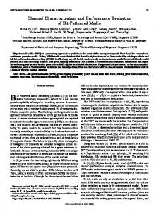
Each AC has its own MAC queue and backoff counter [4]. An AC begin decrementing its backoff counter once the medium has been idle for a period of time defined by the corresponding AC, called the Arbitration InterFrame Space (AIFS). A higher-priority AC will have a shorter AIFS than a lower-priority AC. After waiting for AIFS, each backoff sets a counter to a random number drawn from the interval [1, CW+1]. The minimum size (CWmin [AC]) of the CW is a parameter dependent on the AC. The values of AIFS, CWmin[AC], and CWmax[AC], which are referred to as the EDCF parameters, are announced by the AP via beacon frames [5]. The AP can adapt these parameters dynamically depending on network conditions. These parameters can be used in order to differentiate the channel access among different priority traffic. The IEEE 802.11e defines a transmission opportunity (TXOP) as the interval of time when a particular STA (station) has the right to initiate transmissions. Along with the other parameters of EDCF, the AP also determines and announces the limit of an EDCF TXOP interval for each AC, i.e., TXOPLimit[AC], in beacon frames.
Figure 1.
III.
Four ACs, each with its own queue, AIFS, CW and Backoff
HYBRID COORDINATION FUNCTION CONTROLLED CHANNEL ACCESS
HCCA [6] uses another approach to guarantee QoS. Instead of waiting for idle time for transmission and using a back-off mechanism, it relies on a centralized control in the access point (functioning as the HC, Hybrid Coordinator) that can guarantee the time and duration of the transmission for each of the connected stations. Every station that would like to join the network must request permission from the central access point. This request includes a traffic specification that details the QoS required by the station. The access point then determines if it can support the requested QoS specifications and admits or denies the station. The access point maintains a centralized schedule that is based on the all of its registered stations’ QoS requirements. The access point then notifies each station when it will have access to the wireless medium. Since this process is managed
ISSN : 0975-3397
Vol. 3 No. 3 Mar 2011
1328
R.S.Uppal et al. / International Journal on Computer Science and Engineering (IJCSE)
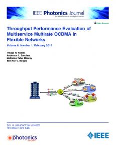
from a central location, it is guaranteed that the access will be contention-free. As everything is predetermined upon registration, HCCA is able to guarantee bandwidth, jitter and latency, which is otherwise challenging in a mixed data and multimedia environment. The HCCA is a continuation of the PCF’s polling scheme. As in PCF, together a Contention Period (CP) and Contention Free Period (CFP) form a superframe. During the CP, access to the wireless medium is managed using EDCF rules. During the CFP, the starting time and maximum duration of each TXOP is specified by the HC, using the QoS CF-Poll frames. Stations will not attempt to get medium access on its own during the CFP, so only the HC can grant TXOPs by sending QoS CF-Poll frames. The CFP ends after the time announced in the beacon frame or by a CF-End frame from the HC. If a station receives a CF-Poll, it is expected to commence data transmission within a Short Inter-Frame Space (SIFS) period, which is smaller than a DIFS. If it does not, the HC can resume control after a PCF Inter-Frame Space (PIFS) time and allocate a new CF-Poll to another station.
Figure 2. 80.11e superframe
An important difference between PCF and HCF is that the HC has priority over all other stations in the WLAN. Since the PIFS is shorter than DIFS and all AIFS, the HC does not have to contend for control of the wireless medium and can initiate HCF access at any time. Thus, stations can be guaranteed predictable transmission opportunity times. However, there are still some problems with the HCCA implementation. A major problem is that HCCA lacks the ability to work with a neighbor legacy network. Since the HCCA AP gains the highest priority medium access over any legacy network during both the CFP and CP, it will interfere with a legacy network that does not support HCCA. IV.
PROBLEM FORMULATION
In this section the performance of IEEE 802.11e is evaluated on the basis of its QoS requirements, using the EDCA model implemented in Qualnet 5.0. QualNet [7] is a comprehensive suite of tools for modeling large wired and wireless networks. It uses simulation and emulation to predict the behavior and performance of networks to improve their design, operation and management. The basic network topology consists of an AP and varying number of stations depending on the simulation scenario. All communications take place between the stations and the AP, i.e., there is no direct communication between stations. All stations are stationary, and transmission powers are set such that all stations are within each other’s transmission ranges. The various other parameters are set as follows: Propagation Model:
Two-ray pathloss
Shadowing Model:
Constant
Radio Type:
802.11b Radio
MAC Type:
802.11e
Antenna Type:
Omni directional
Routing Protocol:
AODV
Traffic Type:
CBR
The QoS requirements vary from application to application and can be classified as the following dimensions: throughput, delay, jitter and data loss. Throughput is the amount of data transferred in a given amount of time, usually expressed in bits per second (bps). It is directly proportional to the available bandwidth/capacity. The throughput required by an application depends on the application characteristics. For example, it depends on various factors like the number of nodes present in the network, number of frames sent, frame size and so on. To ensure that network is working with maximum throughput, an optimum point should be obtained. Maximum
ISSN : 0975-3397
Vol. 3 No. 3 Mar 2011
1329
R.S.Uppal et al. / International Journal on Computer Science and Engineering (IJCSE)
throughput is achieved by controlling the input data rate. The total throughput is defined as the ratio of transmitted data to the transmission cycle duration. Another important measurement is the end-to-end delay, which is the total delay from the time the application at the sender side generates a packet to the time the application at the receiver side receives it. It is the most critical parameter for interactive real-time multimedia applications such as Internet telephony, videoconferencing, VR (Virtual Reality) environments, and multiplayer network games. An another form of delay, which is defined as jitter is the variation in delays, and is of high importance particularly in constant bit rate multimedia applications. A. Number of Nodes The basic network topology consists of 10 nodes/stations. The number of nodes is increased from 10 to 50. At each step, throughput, end-to-end delay and jitter is calculated using the simulator, keeping the data rate constant. “Table II” shows the numeric values of the above said parameters: TABLE II.
NUMBER OF NODES THROUGHPUT, DELAY,JITTER
No. of Nodes
Throughput (kbps)
Delay (ms)
Jitter (ms)
10
4.345
30.6373
12.8591
20
4.227
35.4584
12.1153
30
3.698
54.4953
13.407
40
3.68
94.5431
16.702
50
3.543
90.0966
29.0388
“Table II” shows the decrease in throughput and the rapid increase in delay and jiiter. This is because of the fact as the number of nodes increases, the number of collisions during data transmission increases, thus resulting in the degraded performance by the network. Using “Fig.3” graphical representation is given. 100 90 80 70 60 50 40 30 20 10 0
Throughput (kbps) Delay (ms) Jitter (ms)
10
20
30
40
50
Number of nodes
Figure 3. Graph between no. of nodes and throughput, delay and jitter
B. Frame rate The frame rate depicts the number of frames/data items to be sent, keeping the frame size constant. Initially the 100 frames are sent, and then it is gradually increased to 500 frames. The table shows the numeric values of throughput, delay and jitter and the graph gives its comparative study. TABLE III.
ISSN : 0975-3397
FRAME RATE, THROUGHPUT, DELAY,JITTER
Frame Rate
Throughput (kbps)
Delay (ms)
Jitter (ms)
100
4.345
30.6373
12.8591
200
4.345
30.6373
12.8591
300
4.345
30.6373
12.8591
400
4.345
30.6373
12.8591
500
4.345
30.6373
12.8591
Vol. 3 No. 3 Mar 2011
1330
R.S.Uppal et al. / International Journal on Computer Science and Engineering (IJCSE)
The graph in “Fig.4” shows consistent throughput of 4345bps, delay (30.6373ms) and jitter (12.8591ms) irrespective of the change in frame rate. This happened because the data is transmitted at constant bit rate flow between the nodes. 35 30 25 Throughput (kbps)
20
Delay (ms) 15
Jitter (ms)
10 5 0 100
200
300
400
500
Frame rate
Figure 4. Graph between frame rate and throughput, delay and jitter
C. Frame Size Frame size depicts the number of bytes per frame. The simulation was done by changing the frame size from 512 bytes to 2560 bytes, keeping the frame/data rate constant for CBR. The following table shows the rapid linear increase in the throughput and delay with an increase in frame size. But the jitter remains constant till frames of 1536 bytes and then increases slowly. TABLE IV.
FRAME SIZE, THROUGHPUT, DELAY,JITTER
Frame Size (bytes)
Throughput (kbps)
Delay (ms)
Jitter (ms)
512
4.345
30.6373
12.8591
1024
8.69
38.8293
12.8591
1536
13.035
47.0213
12.8591
2048
17.38
63.3356
13.874
2560
21.725
71.0193
13.4879
The graph in “Fig.5” gives a pictorial view of the parameters when the bytes per frame are increased linearly. 80 70 60 50
Throughput (kbps)
40
Delay (ms)
30
Jitter (ms)
20 10 0 512
1024
1536
2048
2560
Frame size (bytes)
Figure 5. Graph between frame size and throughput, delay and jitter
D. Traffic Sources The traffic source between the nodes for the simulation purpose is CBR (constant bit rate). In CBR frames, the amount of output data per time segment remains constant. i.e. it does not vary. CBR is useful for streaming multimedia content on limited capacity channels. Since it is the maximum bit rate that matters, not the average, so CBR would be used to take advantage of all of the capacity. As the traffic sources, i.e the number of CBR connections are increased to 5 sources, the “Table V” gives the throughput, delay and jitter values.
ISSN : 0975-3397
Vol. 3 No. 3 Mar 2011
1331
R.S.Uppal et al. / International Journal on Computer Science and Engineering (IJCSE)
TABLE V.
CBR CONNECTIONS, THROUGHPUT, DELAY,JITTER
CBR connections
Throughput (kbps)
Delay (ms)
Jitter (ms)
1
4.345
32.7549
11.3028
2
4.227
59.7195
18.0564
3
4.177
82.7976
26.6033
4
3.848
90.384
25.0158
5
3.3898
146.374
24.7726
The graph in “Fig.6” shows the changes in throughput, delay and jitter. Throughput decreases and the increase in delay is massive. The value of jitter increase as the traffic sources are increased and then after attaining a peak value it stabilizes 160 140 120 100
Throughput (kbps)
80
Delay (ms)
60
Jitter (ms)
40 20 0 1
2
3
4
5
CBR connections
Figure 6. Graph between CBR connections and throughput, delay and jitter
V.
CONCLUSION
This paper depicts the performance for QoS provisioning in 802.11 wireless networks in terms of metrics like throughput, end-to-end delay and jitter. It can be concluded that these parameters are highly influenced by the number of nodes present in the network and the traffic sources for constant bit rate transmission. For the better performance of the network it is required that jitter and delay should be less and throughput should be high. The higher throughput can be achieved by having an optimum number of nodes (like 30 in this case) and higher frame rate. The lower value of delay and jitter can be achieved by frame size of optimum level. REFERENCES [1] [2] [3] [4] [5] [6]
IEEE Std. 802.11, Part 11: Wireless LAN Medium Access Control (MAC) and Physical Layer (PHY) Specifications. 1999. IEEE 802.11e/D13.0, Draft Supplement to Part 11: Wireless LAN Medium Access Control (MAC) and Physical Layer (PHY) Specifications: Medium Access Control (MAC) Quality of Service (QoS) Enhancements. January 2005. Bilal Rauf, M Faisal Amjad, Kabeer Ahmed, Natinal University of Sciences and Technology,Pakistan “ Performance Evaluation of IEEE 802.11 DCF in comparison with IEEE 802.11e EDCA”. Zhen-ning Kong, Danny H. K. Tsang, Brahim Bensaou, and Deyun Gao "Performance Analysis of IEEE 802.11e Contention-Based Channel Access", IEEE Journal on Selected Areas in Communications, Vol. 22, No. 10, December 2004. Sunghyun Choi, Javier del Prado, Sai Shankar N, Stefan Mangold, “IEEE802.11e Contention-Based Channel Access (EDCF) Performance Evaluation”. Qiang Ni, National University of Ireland, “Performance Analysis and Enhancements for IEEE 802.11e Wireless Networks”, IEEE Network, August 2005. Scalable Networks Technologies http://www.scalable-networks.com.
ISSN : 0975-3397
Vol. 3 No. 3 Mar 2011
1332