Space Propulsion 2012, 7-10 May 2012, Bordeaux, France.
Performance Characterization of a 100-kW-class Applied-Field MPD thruster Riccardo Albertoni1, Fabrizio Paganucci2, Paola Rossetti3 and Mariano Andrenucci4 Alta S.p.A., Via A. Gherardesca, 5 - 56121, Pisa, Italy
[email protected] SP2012 2350633
An experimental investigation of a pulsed, quasi-steady, 100-kW class applied-field magnetoplasmadynamic (MPD) thruster is discussed. Measurements were obtained with argon propellant for a variety of currents, mass flow rates and magnetic field strengths in a power range between 20 and 250 kW. Tests were carried out in Alta’s IV-10 vacuum facility. With a volume of about 200 m3 , IV-10 allowed for a current-pulse duration up to 1 s maintaining a maximum back-pressure lower than 3 · 10−4 mbar during the shot as well as for the minimization of the environmental interaction with the plume. Although the shot duration was still too short to achieve steady-state thermal conditions, it allows for direct, time-resolved thrust measurements. To this purpose a new single-axis thrust stand was designed to improve the full scale and the frequency response of the existing thrust stands commonly employed for high power devices. A maximum thrust efficiency of about 30% was obtained at 200 kW for an applied magnetic field of 120 mT and a mass flow rate of 60 mg/s. At 100 kW, for the same mass flow rate and magnetic field, a thrust efficiency slightly higher than 20% and a specific impulse of about 2500 s were reached. These results appear very promising since the thruster performance parameters (specific impulse, thrust efficiency and power-to-thrust ratio) are among the highest ever measured for argon-fed MPD thrusters in the power range investigated.
I.
Introduction
Magnetoplasmadynamic (MPD) thrusters represent a valuable option for thrust-demanding missions requiring a significant ∆V such as manned mission precursors to Mars or automatic missions to gas giants, outer planets or to Kuiper-belt objects [1,2] . However, the performance and lifetime demonstrated so far with gaseous propellants are at best marginal for these missions. Efficiencies of up to 25% at 1700 s specific impulse have been achieved with argon propellant in a steady-state applied-field MPD thruster at about 60 kW [3] while, in multi-megawatt quasi-steady self-field thrusters, efficiencies as high as 30% at specific impulses up to 2300 s have been attained using argon [4] . Despite more than 50 years of development, MPD thrusters are far from being a mature technology entailing a slow but constant de1 PhD
Student, Universit` a degli Studi di Pisa Professor, Universit` a degli Studi di Pisa 3 Project Manager, Alta S.p.A. 4 Full Professor, Universit` a degli Studi di Pisa 2 Associate
1 of 8
cline of interest in such a technology. This is due to a variety of shortcomings that have hampered its development, such as cathode erosion, manifestation of an unstable regime beyond a critical operative point as well as lack of high levels of electric power in space. In addition, ground testing is particularly challenging due to the lack of vacuum chambers capable of maintaining back-pressure levels as low as 10−4 mbar to not influence the thruster performance [5] . Nevertheless, MPD thrusters, with their simple and compact design, still basically remain the only possible option among electric-propulsion concepts for future interplanetary missions. Near term, less-ambitious missions, such as LEO to GEO transfer of heavy satellites, may take advantage of the so called applied-field MPD thruster. This type of thruster operates at power levels from tens to few hundreds kW compensating the reduction in the self-induced body force with the application of an external magnetic field arranged in a nozzle fashion toward the exit. Moreover, in order to benefit from the advantages of such a technology on
Space Propulsion 2012, 7-10 May 2012, Bordeaux, France.
today’s power-limited spacecrafts, MPD thrusters can be operated in quasi-steady mode with top-flat current pulses long enough to allow the discharge reaching stationary conditions. This approach was used during most of the MPD spaceflight tests carried out so far: MS-T4 (1981), SEPAC (1983) and SFU (1995) missions [6–8] . In this paper the results of a systematic test campaign on pulsed, quasi-steady applied-field MPD thruster operating with argon are presented and discussed. The pulse duration has been increased to 0.5 s to allow for direct thrust measurements as well as for a better performance comparison with the existing steady-state devices.
II. II.A.
Experimental Apparatus
Thruster
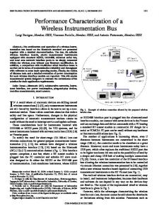
The thruster used in the following experiment (Fig.1) was designed after the Russian ”Ageyev-type” highcurrent plasma accelerator with a central multichannel hollow cathode and a coaxial flared anode [9] . The use of hollow cathodes was shown to increase
Figure 1. Schematic of the 100 kW AF-MPD Thruster
the thrust efficiency with respect to solid rod cathodes [10,11] . However, at typical current levels of 103 A, single channel hollow cathodes (ScHc) require large channel diameters to guarantee a limited erosion rate; typically a current density lower than 1 · 106 A/m2 [12] is suggested. In this conditions the mass flow rates necessary to ensure the so called normal regime [13] may not fulfill the requirements of the thruster. With their capability of sustaining high current densities with a limited gas flow consumption [14] , multi-channel hollow cathodes (McHc) are the most promising options among elementary emitters for high-power applications. Despite such favorable features, few studies have been presented
2 of 8
so far on gas-fed MPD thrusters operating with McHc [15,16] . In the present design, a molybdenum alloy (TZM) cathode with an inner diameter of 40 mm and a wall thickness of 2 mm was adopted. The inside of the cathode was tightly packed with 330 W-La rods of 2 mm diameter and 40 mm length each. The open cross section after filling, Av , was about 220 mm2 leading to a packing porosity of approximately 17%. A slightly divergent (∼ 20 deg) copper anode having a minimum diameter of 100 mm was used for a maximum anode-to-cathode radius ratio, ¯ ≡ Ra /Rc , of about 3. The applied magnetic field R was provided by a 430 turns coaxial solenoid capable of generating a magnetic field strength up to 130 mT with a current of about 60 A. The solenoid was designed to minimize the total mass (∼ 5 kg) and the thermal power losses (< 5 kW ) at the nominal magnetic field of 80 mT as measured on the thruster centerline at the cathode tip. In this condition the applied magnetic field strength was of the same order of magnitude of the self-induced one, namely ¯ ≡ Ba /Bsf ' 4 − 6. B II.B.
Test Facility
The measurements reported in this paper were conducted in the IV-10 facility at Alta. The chamber consists of a cylindrical stainless steel section of 6 m with an inner free diameter of about 6 m. The pumping system currently installed consists of eight pumps and five cold panels capable of an ultimate vacuum level lower than 2 · 10−7 mbar and a pumping rate of about 300,000 l/s of xenon. The pressure is monitored by three Leybold-Inficon ITR90 Pirani/Bayard sensors placed symmetrically on opposite sides of the vessel. The vacuum chamber operated at a base pressure of 1.4 · 10−5 mbar and approximately 2.2 · 10−4 mbar during the thruster operation. After each pulse a minimum of 10 minutes was required for a complete recovery of the base pressure. High-purity, grade 4.8, argon was used as propellant. The gas feeding system consisted of a 8.5 l main reservoir positioned inside the vacuum chamber to prevent air contamination. This system was designed to guarantee a top-flat gas pulse of about 10 seconds. Prior to each shot, the reservoir was filled with argon up to a given pressure corresponding to the desired mass flow rate (225-380 mbar for 60 mg/s and 120 mg/s, respectively). The propellant was injected through the cathode by means of a fast acting solenoid valve (FAV). The time delay between the opening of the FAV and the achievement of a top-flat gas signal was recorded during the calibration procedure [17] and used to trigger the discharge process. The procedure allows the mass
Space Propulsion 2012, 7-10 May 2012, Bordeaux, France.
III.
flow rate to be measured with an overall uncertainty within ±5% of the value. The quasi-steady current pulse to the thruster was provided by a bank of four Maxwell Technologies BMOD-0165 supercapacitors (SCs) in series. Prior to each firing, a dedicated power supply charged the SCs to the voltage value corresponding to an estimated discharge current. The relationship between the charging voltage and the discharge current was preliminary estimated on the basis of previous test campaigns and refined by a dedicated test session. A pulse forming network (PFN) was used as thruster ignitor. The PFN, isolated from the SCs bank via high-currents Semikron SKN-240 diodes, consists in a bank of 180 capacitors and inductances allowing to store energy at a rate of 600 J/s from a HVL Series 311-6203 charging unit. The initiation of the gas breakdown was controlled by the closure of a mercury vapor ignitor. Finally, a customized 240 kW DC power supply was used to provide the current pulse to the solenoid. II.C.
III.A.
Results and Discussion
Data Reduction
Three non-sequential measurements for each operating condition were performed in order to asses the repeatability of the data. For each data point the standard deviation of the sample mean was obtained over an automatically-defined time window. Typical measured arc current and voltage signals along with the considered time window are shown in Figure 2 and Figure 3. The thruster performance was evaluated through the experimental determination of the thrust T . The thrust efficiency was determined as the ratio of directed thrust power to the discharge power P (neglecting the solenoid) as ηT = T 2 / (2mP ˙ ). Error bars account for both the standard deviation and the measurement uncertainty. Where not explicitly indicated, the dimensions of the symbols used are larger than the related error.
Performance Diagnostics
The thrust measurements were recorded using a single axis, double-pendulum thrust stand mounted on a tilting platform to guarantee a proper leveling during the calibration. An electromagnetic calibrator was used to generate a reference force when requested in order to check the response of the thrust stand prior to each firing. The sensing elements are based on high-precision optical stain gages measuring the strain on the flexural elements. The thrust stand frequency response was 15 Hz for a maximum thruster mass of 25 kg. For the performance measurements, thruster operation was monitored in real time by a Tektronix TDS224 digital oscilloscope. The monitored properties include the solenoid current, discharge current and voltage along with the thrust. The terminal voltage was evaluated by independently measuring the cathode-to-GND and the anode-to-GND voltages via Tektronix P5100 voltage probes connected to the feedthrough terminals at the vacuum chamber header. The voltage drop was than obtained by subtracting one signal from the other. The discharge current was measured using a single LEM LT-4000S probe at the cathode cable. The error associated with the DC voltage measurements is ±2% and ±1% for the current measurements. Thrust, specific impulse and thrust efficiency measurement uncertainties were found by accounting for all aforementioned errors resulting in ±5%, ±7% and ±11% relative error, respectively.
Terminal Voltage, V
Figure 2. (Color online) Typical filtered current signals
150
100
50
0 200
400
600
800
1000
1200
1400
Time, ms Figure 3. (Color online) Typical filtered voltage signals
3 of 8
Space Propulsion 2012, 7-10 May 2012, Bordeaux, France.
III.B.
Performance Data
Values of current and voltage for different mass flow rates and applied induction fields are reported in the electrical characteristics of Fig.4, Fig.5 and Fig.6. The V-I data are in good agreement with other experimental observation reported in the literature as far as concerns the increase in terminal voltage with the magnetic field strength. This result is widely known and frequently reported as the magnetic field affects the radial electron mobility toward the anode. The electron mobility in the confining ExB electron drift is provided mainly by the electronneutral collisions entailing an increase in frictional dissipation. For a given magnetic field strength, the terminal voltage was found to be almost constant for a wide range of arc currents (500-2500 A) implying a reduction in the overall load resistance, as shown in Fig.7. Similar results were also reported by Myers [18–20] in an extensive series of experiments on a 100-kW class steady-state thruster as well as by Wegemann [21] and Winter [22] during the testing of the ZT-3, steady-state, thruster.
Figure 5. Electrical characteristics, 80 mg/s
140
Terminal Voltage, V
120 100 80 60 40 20 0 0
50 mT 80 mT 100 mT 120 mT
500
1000 1500 2000 Current, A
Figure 6. Electrical characteristics, 120 mg/s
2500
much like in self-field MPD thrusters [23] . This behavior might be tied with an increased erosion at high currents and, thus, to a higher electron density in the discharge chamber. Nevertheless, it is possible to hypothesize that the evaporated mass was only slightly ionized since, for a given discharge current, a remarkable increase in thrust would be expected in fully ionized conditions. As will be discussed later in detail, no noticeable deviation from a linear trend was actually observed at high current levels. A typical trace of the calibration signal and thrust measurement over time for different levels of the magnetic field strength is shown in Figure 8. The calibration signal was intentionally shifted to allow for a better comparison with the experimental data. It has to be underlined that the thrust signals reported in Figure 8 do not correspond to a constant discharge current since the current delivered by the SCs bank depends upon the load resistance which, in turn, depends on the applied magnetic
3000
Figure 4. Electrical characteristics, 60 mg/s
This trend may indicate that the full ionization regime was not achieved. Under full ionization conditions, the propellant is exhausted at a velocity close to the so called critical ionization velocity (CIV) and it is only after the full ionization condition that the thruster comply with the typical V ∼ I 3 law. For a self-field device, the discharge current correspondp ˙ i /b, ing to the full ionization is given by If i = mε where b is the electromagnetic thrust coefficient. Unfortunately, no such scaling relation exists for applied-field thrusters and thus no estimations can be made to prove the hypothesis of a partially ionized propellant. As regards the terminal voltage at 80 mg/s, the results are somehow unexpected since previous experimental data showed that the voltage drop increases linearly with increasing current
4 of 8
Space Propulsion 2012, 7-10 May 2012, Bordeaux, France.
Figure 7. Load resistance vs discharge current, 120 mg/s
Figure 9. Thrust measurement signal
field strength as well as on the mass flow rate. The T-I curves reported in Figure 10, 11 and 12 show the effectiveness of the applied magnetic field in increasing the thrust for a given discharge current. The thrust increases almost linearly with the discharge current for all the applied magnetic field strengths. This result indicates that the most important contribution to the thrust is the so called ”swirl acceleration” which is expected to scale with IBA at the examined power levels. The thrustto-power ratio, depicted in Figure 13, shows that the thrust efficiency increases much slower than the specific impulse for increasing discharge current indicating that a larger fraction of the total arc power is lost to the electrodes. Moreover, the results suggest that at high current levels the specific thrust levels off at about 10 mN/kW independently from mass flow rate and magnetic field strength. As the power supply mass for a given thrust scales as mP ∼ (T /P )−1 , the results show that it may not be worthwhile to adopt high current levels since it
Figure 10. Thrust vs discharge current, 60 mg/s
may yield to a high power supply mass without significant improvements in thrust efficiency. The specific impulse and the thrust efficiency are shown in Figure 14 and Figure 15. The results show that both the specific impulse and the thrust efficiency increase almost linearly with the arc power. In additions, the performance increase is more sensitive when the mass flow rate is lower. This trend is reasonable since the back-EMF voltage scales as 2 IBA /m. ˙ As shown in Figure 16, the thrust efficiency increases linearly with the specific impulse and is mildly dependent on mass flow rates for a given Isp . III.C.
Cathode Operation
The post-test visual inspection performed after few hundred ignitions (' 500) revealed that the erosion was mainly localized at the main tube annulus. Moreover, the cathode external surface showed current paths twisted in a helical fashion all along the
Figure 8. Thrust calibration signal
5 of 8
Space Propulsion 2012, 7-10 May 2012, Bordeaux, France.
35
5
Thrust−to−Power, mN/kW
80 mT
Thrust, N
4 3 2 1 0 0
500
1000 1500 2000 Current, A
2500
25 20 15 10 5 0 0
3000
1000 1500 2000 Current, A
2500
3000
5000
5 50 mT 120 mT
4000 Specific Impulse, s
4 Thrust, N
500
Figure 13. Thrust-to-power ratio vs discharge current
Figure 11. Thrust vs discharge current, 80 mg/s
3 2
60 mg/s − 120 mT 120 mg/s − 50 mT 60 mg/s − 50 mT 80 mg/s − 80 mT
3000 2000 1000
1 0 0
60 mg/s − 120 mT 120 mg/s − 50 mT 60 mg/s − 50 mT 80 mg/s − 80 mT
30
500
1000 1500 2000 Current, A
2500
0 0
3000
50
100 150 Arc Power, kW
200
250
Figure 12. Thrust vs discharge current, 120 mg/s
Figure 14. Specific impulse vs discharge current
cathode length indicating that the hollow cathode condition was not fully achieved. High-speed photography displayed a preference for attachment on the outer surface lasting for at least 100 ms from the initial breakdown for most operating conditions. As shown in Figure 17, after 400 ms the current seems to attach mostly to the frontal cavities as expected during the hollow cathode operation. No significant variations of the terminal voltage were detected as a consequence of the different cathode operative modes. Nevertheless, Figure 17 revealed that the number of ignited channels increases with the discharge current undergoing a self-adaptation of the cathode cross section to the variable current requirements. However, inactive channels were observed at all the tested conditions suggesting an oversizing of the cathode open cross section. Numerical analysis indicated that the cathode approached an equilibrium temperature of about 2900 K after τeq ' 10 s from the initial breakdown. Since the discharge characteristic time τd ¿ τeq , the cathode bulk re-
mained cold (< 1000 K) so that the thermionic current was at no point a significant fraction of the total discharge current. The current conduction was probably achieved through locally constricted arc (hot spots) even though it was not possible to resolve this phenomenon by the present experiments. Tracks of erosion craters left by spots (surface pitting) were found mainly at the cathode tip. Some qualitative precedent for this finding is provided by Schrade [25] . In addition, it is worthwhile to note that no signs of localized arc attachment or spotty current patterns were observed at the anode surface for all the operative conditions investigated.
IV.
Conclusions
An experimental investigation of a quasi-steady, applied field MPD thruster is described. The results acquired in these experiments have been achieved extending the current pulse duration to 500 ms allowing for a time-resolved thrust measurement. The
6 of 8
Space Propulsion 2012, 7-10 May 2012, Bordeaux, France.
0.5
Thrust Efficiency
0.4
60 mg/s − 120 mT 120 mg/s − 50 mT 60 mg/s − 50 mT 80 mg/s − 80 mT
0.3 (a) t ' 100 ms, I ' 500 A
0.2
(b) t ' 400 ms, I ' 500 A
0.1 0 0
50
100 150 Arc Power, kW
200
250
Figure 15. Thrust efficiency vs discharge current
(c) t ' 100 ms, I ' 1500 A
(e) t ' 100 ms, I ' 2500 A Figure 17. 80 mT
Figure 16. Specific impulse vs thrust efficiency
(d) t ' 400 ms, I ' 1500 A
(f) t ' 400 ms, I ' 2500 A
Thruster front view - m ˙ = 80 mg/s, BA =
Acknowledgments This work was supported by the European Commission in the framework of the HiPER program under the Grant Agreement 218859. The authors wish to acknowledge the skillful laboratory assistance of G. Cifali and C. Tellini.
present results indicate that the thrust is a linear function of IBA suggesting the predominance of the swirl acceleration mechanism in the thrust generation. At 100 kW, a maximum thrust efficiency of about 20% was measured with 60 mg/s of argon and 120 mT whereas at 170 kW a thrust efficiency slightly lower than 30% was reached for a mass flow rate and a magnetic field strength of 120 mg/s and 120 mT, respectively. From the technological point of view, the extended pulse duration highlighted the need of a refractory-metal cathode body since localized arc attachments turned out to be critical in the operative range tested. Although the anode power deposition has been long identified as the main power dissipation mechanism in AFMPD thrusters, no signs of anode erosion or spotty current patterns were found during the test campaign.
References
7 of 8
1
Jones, R. M., ”Comparison of Potential Electric Propulsion Systems for Orbit Transfer,” Journal of Spacecraft and Rockets, Vol. 21, No. 1, 1984, pp. 88-95.
2
Frisbee, R. H., Hofmann, R. J., ”Electric Propulsion Options for Mars Cargo Missions,” AIAA Paper 96-3173, June 1993.
3
Myers, R. M.,”Applied-field MPD Thruster Performance with Hydrogen and Argon Propellants,”Journal of Propulsion and Power, Vol. 9, No. 5, pp. 781-784.
4
Choueiri, E. Y., Ziemer, J. K., ”Quasi-Steady
Space Propulsion 2012, 7-10 May 2012, Bordeaux, France.
Magneto-plasma-dynamic Thruster Performance Database”, AIAA Paper 98-3472, July 1998.
18
5
Sovey, J. S., Vetrone, R. H., ”Test Facilities for High-Power Electric Propulsion,” Journal of Propulsion and Power, Vol. 10, No. 1, 1994, pp. 18-24.
19
6
Kuriki, K., ”The MPD Thruster Test on the Space Shuttle,” Journal of Spacecraft and Rockets, Vol. 16, No. 5, 1979, pp. 326-332.
7
Nakamura, Y., ”Electric Propulsion Works in Japan,” Acta Astronautica, Vol. 16, No. 1, 1987, pp. 367-378.
8
Toki, K., Shimizu, Y.,”Application of MPD Thruster Systems to Interplanetary Missions,” Journal of Propulsion and Power, Vol. 2, No. 6, 1986, pp. 508-512.
9
Ageyev, V. P., Ostrovsky, V. G., ”High-Current Stationary Plasma Accelerator of High Power”, IEPC Paper 93-117, September 1993.
Myers, R. M., ”Applied-Field Geometry Effects,” AIAA Paper 91-2342, June 1991. Myers, R. M., ”Scaling of 100 kW Class Applied Field MPD Thrusters,” AIAA Paper 92-3462, July 1992.
20
Myers, R. M., Soulas, G. S., ”Anode Power Deposition in Applied-Field MPD Thrusters”, AIAA Paper 92-3463, July 1992.
21
Wegemann, T., Auweter-Kurtz, M., ”Experimental Comparison of Steady State Nozzle Type and Cylindrical MPD Thrusters at High Current Levels,” IEPC Paper 93-122, September 1993.
22
Winter, M., Auweter-Kurtz, M., ”Experimental and Numerical Investigation of Steady State MPD Thrusters,” IEPC Paper 97-113, August 1997.
23
Paganucci, F., Rossetti, P., ”Performance of an Applied-Field MPD Thruster with a Pre-Ionization Chamber”, IEPC Paper 03-302, September 2003.
10
Kimura, I., Arakawa, Y., ”Effect of Applied Magnetic Fields on Physical Processes in an MPD Arcjet,” AIAA Journal, Vol. 15, No. 5, pp. 721724.
24
Maecker, H., ”Plasmastr¨omungen in lichtb¨ogen infolge eigenmagnetischer kompression,” Zeitschrift f¨ ur Physik, Bd. 141, pp. 128-216.
25
Schrade, H., Auweter-Kurtz, M., ”Cathode Phenomena in Plasma Thrusters,” AIAA Paper 871096, May 1987.
11
Babkin, G. V., Mikhalev, V. G.,”Experimental Investigation of the Plasma in a Multichannel Cathode,” Journal of Applied Mechanics and Technical Physics, Vol. 17, No. 6, pp. 767-770.
12
Tsydypov, B. D., ”On Optimization of Thermal Modes of High-Current Thermal Emission Cathodes,” Thermophysics and Aeromechanics, Vol. 14, No. 2, pp.257-263.
13
Ferreira, C. M., Delcroix, J. L., ”Theory of the Hollow Cathode Arc,” Journal of Applied Physics, Vol. 49, No. 4, pp. 2380-2395.
14
Delcroix, J. L., Minoo, H., ”Gas Fed Multichannel Hollow Cathode Arcs,” Review of Scientific Instruments, Vol. 40, No. 12, pp. 1555-1563.
15
Moeller, R. C., Polk, J. E., ”Preliminary Characterization of an MPD Thruster with Extended Anode and Multichannel Hollow Cathode,” AIAA Paper 05-4247, July 207.
16
Tikhonov, V. B., Semenikhin, S. A., ”Research of Plasma Accelerator Processes in the Self-field and Applied Magnetic Field Thrusters,” IEPC Paper 93-076, September 1993.
17
Andrenucci, M., Paganucci, F., ”Scale and Geometric Effects on the Performance of MPD Thrusters,” AIAA Paper 92-3159, July 1992. 8 of 8