2012 IEEE Wireless Communications and Networking Conference: MAC and Cross-Layer Design
Performance Comparison of Downlink User Multiplexing Schemes in IEEE 802.11ac: Multi-User MIMO vs. Frame Aggregation Jiyoung Cha, Hu Jin*, Bang Chul Jung**, Dan Keun Sung Department of EE, KAIST, Republic of Korea *Department of ECE, University of British Columbia, Canada **Department of ICE, Gyeongsang National University, Republic of Korea Email:
[email protected],
[email protected],
[email protected],
[email protected]
Abstract—IEEE 802.11ac standard has newly adopted a downlink multi-user multiple-input and multiple-output (DL-MUMIMO) scheme. For user multiplexing in downlink WLAN, we can also use a frame aggregation scheme for multiplexing multiple users’ data with space-time block coding (STBC) for achieving spatial diversity. We compare the performance of the two downlink user multiplexing schemes: multi-user MIMO and frame aggregation in IEEE 802.11ac. If each user’s encoded data stream has a similar length, the multi-user MIMO scheme yields better average throughput than the frame aggregation scheme. On the other hand, if each user’s encoded data stream has a different length, the frame aggregation scheme outperforms the multi-user MIMO scheme in terms of average throughput. In a fast-varying channel, the multi-user MIMO scheme yields worse throughput due to the channel feedback overhead, compared to that with the frame aggregation scheme. We also observe that the multi-user frame aggregation scheme with STBC always outperforms a single-user transmission scheme with STBC in terms of average throughput due to enhanced MAC layer efficiency through frame aggregation.
I. I NTRODUCTION Recently, a new amendment for WLAN standard IEEE 802.11ac [1] has been under development, which aims to provide at least one Gbps for multi-station throughput and at least 500 Mbps for a maximum single link throughput. For this purpose, the standard has been extended with new features, such as wider RF bandwidth (up to 160 MHz), up to 8 MIMO spatial streams, and high-density modulation with up to 256 QAM and also has adopted a downlink multi-user multiple-input and multiple-output (DL-MU-MIMO) scheme. The DL-MU-MIMO scheme enables an access point (AP) to simultaneously transmit multiple data streams for multiple stations (STAs) by taking advantage of a multiplexing gain through spatial division multiplexing. In this scheme, independent data streams for multiple users are multiplexed in a single physical layer convergence procedure (PLCP) protocol data unit (PPDU) where each data stream is encoded with each corresponding user’s data rate, which is determined by the channel gain in the AP-receiver link. Another MIMO transmission scheme that can support multiple users’ data streams in a single PPDU in downlink is to aggregate the multiple users’ data streams in series and
978-1-4673-0437-5/12/$31.00 ©2012 IEEE
transmit the aggregated frame with Space-Time Block Coding (STBC) through multiple transmit antennas. This scheme takes advantage of a diversity gain instead of a multiplexing gain by transmitting the same data through multiple transmit antennas. This scheme is here called the DL MU frame aggregation (DLMU-FA) scheme with STBC. The WLAN standard specifies two frame aggregation (FA) schemes: an aggregate medium access control (MAC) service data unit (A-MSDU) and an aggregate medium access control (MAC) protocol data unit (A-MPDU). However, these schemes can be applied to only the frames destined to a single user because the aggregation is performed in MAC layer. Singh et al. [3] proposed an aggregate physical service data unit (A-PSDU) scheme which allows frame aggregation to multiple destinations by encoding each frame with different data rates. In this scheme, multiple PSDUs are aggregated in series with delimiting physical signaling filed, HT-SIG field, in front of every PSDU. They also proposed the structure of HT-SIG field, which delivers the required information at the receivers for distinguishing and decoding their own data stream in several subfields, including the length, and modulation and coding scheme. Previously, several MU-MIMO schemes in WLAN have been investigated in many studies. Jin et al. proposed to use an MU-MIMO scheme as a collision mitigation scheme in uplink [4] and compared the performance with that of a single-user (SU) MIMO scheme [5]. In downlink, Gong et al. [6] proposed a new carrier sense multiple access/collision avoidance (CSMA/CA) MAC protocol for DL-MU-MIMO with three response mechanisms for MAC layer efficiency, and Florian et al. [7] investigated the capacity of DL-MU-MIMO channels with codebook-based limited feedback. However, these studies did not consider a tradeoff among downlink multi-user transmission schemes available in a given condition (e.g. the number of transmit antennas and the number of users supported in one transmission) in a practical system based on IEEE 802.11ac. In this paper, we investigate a tradeoff problem between the DL-MU-MIMO scheme and DL-MU-FA scheme with STBC in IEEE 802.11ac system. Since a frame aggregation for
1524
h11 h21
2
User 2
1
hN
AP
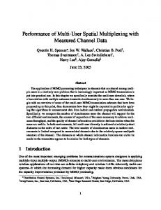
fairness in the comparison of the three transmission schemes, we consider an AP with two transmit antennas and two receivers with one antenna for each. For a larger number of transmit and receive antennas and more receivers with a proper STBC scheme, the similar analysis of this paper can be applied. In the following subsections, we describe the details of the three transmission schemes available in the system described above which are the DL-MU-MIMO scheme, the DL-FA scheme with STBC, and the DL-SU scheme with STBC.
User 1
1
. . .
. . .
. . .
hNM M
User N
Fig. 1.
System model
A. DL-MU-MIMO scheme multiple destinations has not been specified yet in the standard, we use the A-PSDU aggregation frame structure proposed in [3]. We also study the performance of a downlink single-user transmission scheme with STBC, called the DL-SU scheme with STBC, for comparison, which supports one user in each transmission. The rest of this paper is organized as follows: In Section II, we describe three transmission schemes: a DL-MU-MIMO scheme, a DL-MU-FA scheme with STBC, and a DL-SU scheme with STBC. In Section III, based on the analysis of single-link ergodic capacity for each scheme, we analyze the performance of each scheme in terms of average system throughput. In Section IV, we show the performance comparisons of the schemes. Finally, we make conclusions in Section V. II. S YSTEM M ODEL Fig. 1 shows the system model where we consider an AP with M antennas transmits data streams to N users in downlink. Although each user may have multiple antennas, we assume each user has one antenna in this paper. In this system model, channel matrix H can be written as H = [h1 T , h2 T , · · · , hN T ]T ,
(1)
where [·]T is the matrix transpose and hi = (hi1 , hi2 , · · · hiM ) represents the channel gains from M antennas of the AP to the i-th receiver antenna. We assume Rayleigh fading where each channel coefficient hij (j = 1, 2, · · · , M ) is an independent, zero-mean, complex Gaussian random variable with a variance of 2σi2 , which depends on the distance between the transmitter and the receiver. Since each receiver may be located at a different distance from the AP, each value of σi2 may be different. The signal received at the receiver side y = (y1 , y2 , · · · yN )T is y = Hx + n,
The DL-MU-MIMO scheme has been adopted in IEEE 802.11ac, by which the AP can transmit multiple users’ data streams at the same time using a MIMO transmission. With an appropriate MIMO technology, a multiplexing gain can be obtained by creating multiple parallel links from AP to multiple users. In downlink, since the receivers cannot share the received channel coefficients at each antenna, the transmitter should apply precoding to the transmitted symbols. Through precoding, multiple users’ data streams can be multiplexed in one PPDU at the transmitter, and the inter-user interference can be canceled out at the receiver, and, thus, multiple parallel links, AP to multiple users, can be generated. Fig. 2(a) shows the procedure for creating a DL-MU-MIMO PPDU. Each user’s PSDU is encoded independently with its own data rate before it is multiplexed with other PSDUs through precoding, and the resulting multiplexed frame is attached to a single PHY header. Each receiver can decode its own data stream using the information, such as the data rate and the relative position of each user’s data stream delivered in the PHY header as specified in the standard IEEE 802.11ac. As shown in Fig. 2(a), if the time required for transmitting each user’s payload encoded with each user’s data rate, called the PSDU-TXTIME of each user, is different from each other, part of link capacity is wasted when they are transmitted at the same time in a single PPDU, because the transmission time of the resulting multiplexed PSDU is determined by the maximum of all the users’ PSDU-TXTIME values. In other words, the resulting multiplexing gain is reduced. Moreover, for the precoding at the transmitter, the standard requires the receivers to feedback the beamforming feedback matrix obtained from the measured channel coefficients in a compressed form of a sequence of angles, while the STBC scheme does not require the feedback of channel state information from receivers. This feedback is another overhead for the DL-MU-MIMO scheme.
(2)
where x = (x1 , x2 , · · · xM )T denotes the transmitted symbol from the M transmit antennas of the AP and n is a complex Gaussian vector where each component has a zero mean and a variance of N0 . The IEEE 802.11ac standard supports STBC using the Alamouti’s code [1], which is designed only in the case that two transmit antennas are used to transmit one data stream. For
B. DL-FA scheme with STBC An AP can support to transmit a single PPDU to multiple destinations simultaneously through a DL-MU-FA scheme with STBC which aggregates the multiple users’ data streams in series and then transmits the aggregated frame with STBC using multiple transmit antennas. Through transmitting the same data with multiple transmit antennas, the DL-MU-FA
1525
user A
Payload
comparison, we consider a scheme where the AP transmits each user’s data in different PPDUs, each of which needs separate channel access, and, thus, this scheme has additional MAC overhead of channel access for every user, as shown in Fig. 2(c). It also uses STBC with multiple transmit antennas to obtain a diversity gain.
user B encoding
user A
PSDU
user B
PSDU-TXTIME of user A
precoding
Wasted! user A
PPDU TX
from user A
from user B
ACK
ACK
III. P ERFORMANCE A NALYSIS In order to compare the performance of the three transmission schemes described in Section II, we first analyze the ergodic capacity of a single link for each scheme, and using this result, we analyze the average throughput based on the specification of IEEE 802.11ac.
PH user B CH. Access
time
PSDU-TXTIME of user B
SIFS
SIFS
(a) DL-MU-MIMO scheme
Payload
user A
A. Ergodic Capacity The ergodic capacity of a single AP-receiver link depends on the physical layer technologies, 1) MIMO precoding for the DL-MU-MIMO scheme, 2) STBC for the DL-MU-FA scheme and the DL-SU scheme. We analyze the ergodic capacity for those two base technologies. For the DL-MU-MIMO scheme, the transmitter should apply precoding to the transmitted symbols, and the received signal can be rewritten as
user B
encoding user A
PSDU
user B
aggregation
PPDU TX
PH
user A
CH. Access
from user A
from user B
ACK
user B
ACK time
PD
SIFS
SIFS
(b) DL-FA scheme with STBC
Payload
user A
y = Hx + n = HW s + n,
where W = [w1 , w2 , · · · , wN ] is the precoding matrix, and s = (s1 s2 · · · sN )T denotes the N users’ data symbols. wi = (wi1 , wi2 , · · · wiM )T is the i-th column vector of the precoding matrix. We use a zero forcing (ZF) precoder, which uses the pseudoinverse of H, H † , to cancel out the inter-user interference at the receiver, where
user B
encoding
PSDU
user A
user B
from user B
from user A PPDU TX
PH
CH. Access
user A
ACK SIFS
PH
user B
CH. Access
ACK SIFS
time
V = [v 1 , v 2 , · · · , v N ] = H † = H H (HH H )−1 . Then, we define the precoding matrix W as a column-wise normalized V matrix [8] as
(c) DL-SU scheme with STBC Fig. 2.
(3)
Transmission procedure of the three schemes
scheme with STBC can achieve higher link capacity with a diversity gain. Fig. 2(b) shows how to create a PPDU in the DL-MU-FA scheme with STBC. Since the IEEE 802.11ac does not specify a frame aggregation scheme for multiple destinations, we use the A-PSDU model proposed in [3]. Each STA’s PSDU is encoded independently with its own data rate which is higher than that for the DL-MU-MIMO scheme. When PSDUs are aggregated in a PPDU, the Physical layer Delimiter (PD), HTSIG in [3], needs to be attached in front of each PSDU to distinguish and provide information for decoding each frame to the receivers. Since all the receivers need to know the PDs, they are encoded with the lowest MCS level. The presence of PDs and the lowest coding rate can be an additional overhead for this scheme.
W = [w1 , w2 , · · · , wN ] v v v 1 2 N = √ ,√ ··· , √ H H H [V V ]11 [V V ]22 [V V ]N N [ v1 v2 = √ ,√ , H −1 [(HH ) ]11 [(HH H )−1 ]22 ] vN ··· , √ , [(HH H )−1 ]N N (4) where [A]ii is the element of a matrix A in the i-th row and the i-th column. Using the fact that hi v i = 1, and hi v j = 0 for j ̸= i, the received signal at receiver i can be written as ∑ y i = hi wi si + hi wj sj + ni j̸=i
C. DL-SU scheme with STBC
si
Different from the above two MU transmission schemes, an AP can transmit a PPDU to only a single user at a time. For
1526
=√ + ni . [(HH H )−1 ]ii
(5)
12
B. Average Throughput Ergodic capacity (bits/s/Hz)
10
We define the average throughput as
8
6
4
2
MIMO precoding STBC
0 -5
0
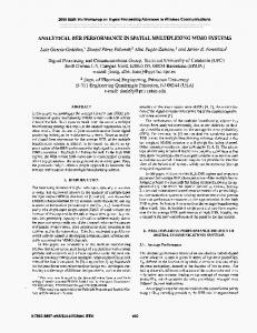
Fig. 3.
5
10 15 20 Average received SNR (dB)
25
30
Ergodic capacity of a single link
Therefore, the average received SNR at the i-th user is expressed as γi =
E[|si |2 ] γ0 = , H −1 [(HH ) ]ii N0 [(HH H )−1 ]ii
(6)
where γ0 is defined as E[|si |2 ]/N0 . The term 1/[(HH H )−1 ]ii has a Chi-square distribution with 2(M − N + 1) degrees-offreedom (DoFs) and variance σi2 [5]. For STBC, we use Alamouti scheme as defined in IEEE 802.11ac, which uses the following space-time block code, ( ) s1 −s∗2 . s2 s∗1 Assuming that two timely consecutive channel gains of a link from the j-th AP antenna to the i-th user are identical, in other words hij = hij [t] = hij [t + 1] (i, j = 1, 2), we can prove that the received SNR at i-th user is (|hii | + |hij | )E[|si | ] = (|hii |2 + |hij |2 )γ0 , N0 2
γi =
sum of payload size for all destination users , E[time for transmission(s) for all destination users] (9) where the destination users represent the users to which the AP transmits data for an MU transmission. The total transmission time is the time duration from the instant that the AP starts a channel access algorithm to the instant that the AP receives acknowledgement (ACK) frames from all the destination users. The IEEE 802.11 MAC exploits the CSMA/CA with binary exponential backoff algorithm for channel access. In this algorithm, a transmitting STA performs random backoff after the channel is idle during DCF interframe space (DIFS) period. The backoff counter value is selected in the interval of (0, CW − 1), where CW is the contention window size and is initially set to a minimum value CWmin . After the random backoff procedure is over, the STA transmits its data. If a collision occurs during the transmission, the STA performs the same procedure again with an increased CW value. In this paper, to focus on the performance of the three transmission schemes in the PHY layer, we consider there are a small number of STAs so that collisions do not occur and, thus, STAs always perform the backoff algorithm with the CWmin value. Therefore, the average channel access time, TCA , can be approximated as S=
2
2
(7)
where t is a time instance and the term (|hii |2 + |hij |2 ) has a Chi-square distribution with 4 DoFs and variance σi2 . We can obtain the ergodic capacity (bits/s/Hz) of a single AP-receiver link for both base technologies which is given as [5] ∫ ∞ Ci = log2 (1 + γi )fK (γi )dγi , 0 ( ) ( ) K log2 (e) exp γ1i ∑ 1 k = γ Γ −K + k, , (8) i γi γi K k=1
where fK (γi ) is the probability density function of γi , γi is the average received SNR per spatial stream which is given as 2σi2 γ0 , K is the DoFs of γi , and Γ(·, ·) is the complementary incomplete gamma function. Fig. 3 shows the single link ergodic capacity of the two base technologies, the MIMO precoding and the STBC, for varying γi in the case of an AP with two transmit antennas and two users with one receive antenna for each. We use this result as maximum achievable spectral efficiency to calculate the average throughput of each scheme in Subsection III-B.
TCA ≈ TDIF S + E[backoff counter] × TSLOT CWmin = TDIF S + × TSLOT , 2
(10)
where TDIF S is DIFS time period and TSLOT is the slot time. As mentioned in Subsection II-A, the DL-MU-MIMO scheme requires the compressed beamforming matrix feedback from receivers, and the standard specifies a sequence of the compressed beamforming matrix feedbacks from multiple users. Since this overhead is not negligible, 1000 bits for 20MHz except PHY header, the period of feedback is an important factor in the performance of the DL-MU-MIMO scheme and it depends on how fast the channel varies. We model this feedback period, PCH , as the number of transmissions during which the feedback does not need to be updated. For example, if the channel coefficients stay in the same values during the transmission of 10 DL-MU-MIMO PPDUs, and, thus, the feedback sequence is not required during this period, the value of PCH is 10. Therefore, the feedback overhead time per one DL-MU-MIMO transmission, TF B , is equal to 1/PCH times TF B,total , where TF B,total is the total time elapsed for an MU compressed beamforming matrix feedback sequence. The standard acknowledgement (ACK) procedure for the new MU-MIMO scheme in the IEEE 802.11ac is still in progress and, thus, we consider a simple ACK procedure assuming an error-free channel and using the fact that each user knows the position of its own data stream among all the multiplexed streams through the new PHY header format for the DL-MU-MIMO scheme in the standard. The same PHY
1527
header format can be used in the DL-MU-FA scheme with STBC. As shown in Fig. 2(a) and Fig. 2(b), a short interframe space (SIFS) period after the reception of an MU PPDU, the user, who received the data stream in the first position in the DL MU PPDU, transmits an ACK frame and another SIFS period after this transmission, the second user transmits an ACK. In the case of the DL-MU-MIMO scheme, the transmission time of multiplexed multiple users’ data streams is determined by the maximum value among the PSDU-TXTIME values of all the receiving users, defined in Subsection II-A. Therefore, the average throughput of the DL-MU-MIMO scheme is expressed as ∑N i=1 Li SM M = , TO,M M + maxi=1,··· ,N {(Li + Bover )/Ri,P re } (11)
where TO,M F S = TCA + TP H + N (TP D + TSIF S + TACK ). Ri,ST BC is the data rate using STBC for the i-th user and TP D denotes the PD transmission time. For the DL-SU scheme with STBC, we should take into account multiple transmissions to all the destination users of the above MU transmission schemes for fair comparison. Then, the average throughput for this scheme is expressed as ∑N i=1 Li SSS = , (13) ∑N TO,SS + i=1 {(Li + Bover )/Ri,ST BC } where TO,SS = N (TCA + TP H + TSIF S + TACK ). IV. N UMERICAL R ESULTS As mentioned in Section II, since IEEE 802.11ac supports STBC using the Alamouti’s code designed only for the two transmit antenna case, we consider the two-user case in downlink for fair comparison, where an AP has two transmit antennas and each user has one antenna. User A and user B have average received SNR values per spatial stream of γA and γB , respectively, and their payload sizes are denoted by LA and LB , respectively. Based on the analysis in Section III, we calculate the average throughput of the three transmission schemes, the DL-MU-MIMO scheme, the DL-MU-FA scheme
AND
TABLE I PHY LAYER
TDIF S TSIF S TSLOT TACK TP H Bover CWmin Feedback overhead Bandwidth
PARAMETERS
34 µs 16 µs 9 µs 64 µs 44 µs 16 bits 15 1000 bits 20 MHz
40
35
Average throughput (Mbps)
where TO,M M = TF B + TCA + TP H + N (TSIF S + TACK ). Li and Ri,P re represent the payload size and the data rate using MIMO precoding for the i-th user, respectively. N is the number of receiving users and TP H and TACK denote the transmission time of PHY header and an ACK frame, respectively. TSIF S is the SIFS period and Bover is the number of overhead bits in a PSDU. For the DL-MU-FA scheme with STBC, since each user’s PSDU is transmitted one after another, the transmission time of the aggregated PSDU is the sum of the PSDU-TXTIME of each receiver. Thus, the average throughput of this scheme, considering the PD overhead, is expressed as ∑N i=1 Li SM F S = , (12) ∑N TO,M F S + i=1 {(Li + Bover )/Ri,ST BC }
MAC
30
25
20
15 DL MU MIMO DL MU FA with STBC DL SU with STBC 10 -5
0
5 10 15 20 Average received SNR of user B (dB)
25
30
Fig. 4. Average throughput for varying γB when γA = 10dB, LA = LB = 1000bytes, and PCH = 30
with STBC, and the DL-SU scheme with STBC. Table I shows the MAC and PHY layer parameters used in numerical results, which are obtained from IEEE 802.11n [2] and IEEE 802.11ac specification [1]. Fig. 4 shows the average throughput for varying γB when γA is set to 10dB, LA and LB are set to 1000 bytes, and PCH is set to 30. For the DL-MU-MIMO scheme, when γB is less than the value of γA , the average throughput increases as the γB increases, and then it does not vary although γB varies when γB is greater than the value of γA . This is because when each user’s payload size has the same length, the lowest data rate, that is, the lowest average received SNR value of all receiving users determines the performance. In addition, when γB is equal to γA , the DL-MU-MIMO transmission scheme fully utilizes the two degrees-of-freedom, that is, the two parallel AP-receiver links are used for transmitting meaningful data during the whole transmission time, and the resulting average throughput at this point and around this point is higher than that for other schemes. Specifically, when γB is equal to γA , the average throughput of the DL-MU-MIMO scheme is 11.7 percent higher than that of the DL-MU-FA scheme with STBC and 41.7 percent higher than that of the DL-SU scheme with STBC. In other γB region, the DL-MU-FA scheme with STBC yields the best performance. The DL-SU scheme with STBC always yields worse performance than the DL-MUFA scheme with STBC, due to an additional channel access time of 67.5 µs, which is longer than the additional overhead of the DL-MU-FA scheme with STBC, 2TP D = 8µs. The performance difference between those two STBC schemes becomes larger as the data rate of user B increases. In other
1528
70
Average throughput (Mbps)
60
This is because in high SNR region, the ratio of the single link ergodic capacity of the STBC to that of the SM is even smaller than in low SNR region, as shown in Fig. 3, and, thus, the aggregated two link capacity of the DL-MU-MIMO scheme compensates for the waste and outperforms the DLMU-FA scheme with STBC.
DL MU FA with STBC DL SU with STBC DL MU MIMO (PCH=1) DL MU MIMO (PCH=10)
50
DL MU MIMO (PCH=30) DL MU MIMO (PCH=50)
40
V. C ONCLUSION
30
20
10 2 10
3
10 Payload size of user B (bytes)
4
10
Fig. 5. Average throughput for varying LB when LA = 1000bytes, γA = γB = 10dB, and PCH = 1, 10, 30, 50 γA = γB + 10dB 45
Average throughput (Mbps)
40
35
30
25
20
15
10 -5
DL MU MIMO DL MU FA with STBC 0
5 10 15 Average received SNR of user B (dB)
In this paper, we investigated a trade-off between the DLMU-MIMO scheme and the DL-MU-FA scheme with STBC which support downlink multi-user transmission by using MIMO technologies. In addition, the DL-SU scheme with STBC was also studied for comparison between the MU transmissions and SU transmissions. For comparison of the performance among the three schemes, we first analyzed the single-link ergodic capacity for the base technologies: spatial division multiplexing and STBC, and used these results to obtain the average throughput for each scheme. If each user’s encoded data stream has a similar length, the DL-MU-MIMO scheme yields better performance by fully utilizing multiple parallel links, while if there is a need for frequent feedback because of the fast-varying channel and the encoded data streams have different lengths, the DL-MU-FA scheme with STBC yields better performance. The DL-MU-FA scheme with STBC always outperforms the DL-SU scheme with STBC due to enhanced MAC layer efficiency through frame aggregation. ACKNOWLEDGMENT
20
Fig. 6. Average throughput for varying γB satisfying γA = γB + 10dB when LA = LB = 1000bytes, and PCH = 30
words, the transmission time decreases, which makes the effect of the overhead more dominant. Fig. 5 shows the average throughput for varying the payload size of user B, LB , when LA is set to 1000 bytes, γA and γB are set to 10dB, and PCH is set to 1, 10, 30, and 50. We can observe that the performance of the DL-MU-MIMO scheme has the best performance around the point, where LB = LA , except when PCH is equal to 1, where the average throughput is lower than that of the DL-SU scheme with STBC. As the PCH increases, the performance becomes better because the channel feedback overhead becomes smaller. When PCH is equal to 50, the average throughput of the DL-MU-MIMO scheme is 13 percent higher than that of the DL-MU-FA scheme with STBC and 43.5 percent higher than that of the DL-SU scheme with STBC. Fig. 6 shows the average throughput of both the DL-MUMIMO scheme and the DL-MU-FA scheme with STBC for varying γB , satisfying γA = γB + 10dB when LA and LB are set to 1000 bytes, and PCH is set to 30. In low SNR region, the DL FA scheme with STBC yields better performance because the link capacity of the DL-MU-MIMO scheme is wasted due to a difference between γA and γB . However, in high SNR region, the DL-MU-MIMO scheme yields better performance.
This research was supported by KAIST(Korea Advanced Institute of Science and Technology) under the Seed Money Project and was supported by the MKE(The Ministry of Knowledge Economy), Korea, under the ITRC(Information Technology Research Center) support program supervised by the NIPA(National IT Industry Promotion Agency) (NIPA2012-(C1090-1211-0011)). R EFERENCES [1] Wireless LAN Medium Access Control (MAC) and Physical Layer (PHY) Specifications: Enhancements for Very High Throughput for Operation in Bands below 6GHz, IEEE P802.11ac/D1.0 Std., Jan. 2011. [2] Wireless LAN Medium Access Control (MAC) and Physical Layer (PHY) Specifications: Enhancements for Higher Throughput, IEEE P802.11n Std., Sep. 2009. [3] M. Singh, et al., ”Wwise Proposal: High Throughput Extension to the 802.11 standard,” IEEE 802.11-04/886r6, 2005. [4] H. Jin, B. C. Jung, H. Y. Hwang, and D. K. Sung, A MIMO-based collision mitigation scheme in uplink WLANs, IEEE Commun. Lett., vol. 12, no. 6, pp. 417.419, June 2008. [5] H. Jin, B. C. Jung, H. Y. Hwang, and D. K. Sung, Performance comparison of uplink WLANs with single-user and multi-user MIMO schemes, in Proc. IEEE Wireless Communications and Networking Conference (WCNC), pp. 1854.1859, Mar. 31-Apr. 3 2008. [6] M.X. Gong, E. Perahia, R. Stacey, R. Want, and S. Mao, A CSMA/CA MAC protocol for multi-user MIMO wireless LANs, in Proc. IEEE GLOBECOM 2010, Miami, FL, Dec. 2010, pp.1.6. [7] F. Kaltenberger, M. Kountouris, D. Gesbert, and R. Knopp, On the tradeoff between feedback and capacity in measured MU-MIMO channels, IEEE Trans. Wireless Commun., vol. 8, no. 9, pp. 4866.4875, Sep. 2009. [8] J.Wang, Z. Liu, Y. Wang, and X. You, ”Performance of the zero forcing precoding MIMO broadcast systems with channel estimation errors,” Journal of Electronics (CHINA), Vol.24, No.4, pp. 490.495, July. 2007.
1529