invested vast effort in physical design related research, ... Several excellent reviews of physical design ... We present a complete design methodology by incor-.
Performance-Driven Soft-Macro Clustering and Placement by Preserving HDL Design Hierarchy Hsiao-Pin Su, Allen C.-H. Wu, and Youn-Long Lin Department of Computer Science, Tsing Hua University Hsinchu, Taiwan, 300, Republic of China Abstract In this paper, we present a performance-driven softmacro clustering and placement method which preserves HDL design hierarchy to guide the soft-macro placement process. We also present a complete chip design methodology by integrating the proposed method and a set of commercial EDA tools. Experiments on three industrial designs ranging from 75K to 230K gates demonstrate that the proposed soft-macro clustering and placement method improves critical-path delay on an average of 24%.
1 Introduction
Over the past decades, academia and industry have invested vast e�ort in physical design related research, including oorplanning, partitioning, placement, and routing. Several excellent reviews of physical design techniques are given by [1, 2, 3, 4]. By integrating various techniques, many design methods and software systems have been developed for chip designs. One of the most popular design methods uses schematics as the design entry, followed by oorplanning, placement, and routing to produce nal chip layouts. This design method is very e�ective and e�cient on small to medium-scaled designs. However, with the advent of deep-submicron technology, more and more devices can be packed into a very complex single chip. Due to the time-to-market pressure of designing complex chips and the maturity of synthesis tools, more and more integrated-circuit designers use an HDL-based synthesis approach to develop and manage large designs. Furthermore, as devices geometries shrink, a new set of design challenges, especially in electrical characteristics of circuits, are faced by integrated-circuit designers. This has led to a new research direction in design automation at synthesis and physical levels. Recently, several |||||||||||||{ This work was supported by the National Science Council of
R.O.C. under Grant NSC 87-2215-E-007-011 and NSC 87-2215E-007-017.
HDL design description
HDL Synthesis
Top module M1 M_11
HDL design description
M2
Floorplanning M_12 P&R
Preserving HDL design hierarchy for soft−macro placement?
A complete chip design methodology?
Back−annotation HM HM
Timing analysis SM OK
HM Final layout
Chip layout (a)
(b)
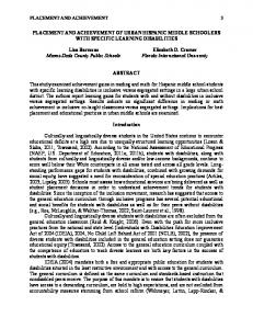
Figure 1:
A typical HDL-based method for macro-based designs: (a) the design ow, (b) problem description.
papers [5, 6, 7, 8] have addressed the challenges and considerations in physical designs targeted to deepsubmicron processes. In this paper, we propose a soft-macro clustering and placement technique which preserves the HDL design hierarchy to guide the soft-macro placement process. We present a complete design methodology by incorporating the proposed soft-macro clustering and placement technique for high-performance chip designs. Experiments on a number of industrial designs have been conducted to demonstrate the e�ectiveness of the proposed method. The rest of the paper is organized as follows. Section 2 describes the problem. Section 3 presents the proposed design ow. Section 4 gives experimental results. Finally, Section 5 draws concluding remarks.
2 Problem description
Figure 1(a) shows a typical HDL-based chip design
ow. It consists of ve steps: (1) HDL synthesis, (2)
oorplanning, (3) place and route, (4) back annotation, and (5) post-layout timing analysis. The input to the
design ow is a mixed RTL and gate-level HDL description in Verilog or VHDL. The HDL-based design speci cation is usually described as a set of hierarchical modules containing hard macros (e.g., prede ned blocks with xed size and IO-pin location) and soft macros (e.g., can be implemented with a exible layout style such as standard-cell style). In the rst step, a synthesizer converts an HDL design description into a hierarchical gate-level netlist by performing HDL compilation and a series of RTL and logic synthesis tasks. In the second step, a oorplanning procedure is invoked to determine the location of each macro on the layout plane. In the third step, a placement-and-routing procedure is used to perform detailed gate-level placement and routing. In the fourth step, the circuit parasitic information is extracted. Finally, a post-layout timing analysis procedure is performed to determine the most critical paths and their delays. If the timing does not satisfy the design requirement, a re nement iteration will proceed until the timing requirement is satis ed. The re nement procedure can be applied at di�erent design levels. For instance, we can re-synthesize certain modules or insert drivers along the critical paths to speed up the circuit timing. We can also adjust the oorplan or re-run a performance-driven oorplanning procedure guiding by the post-layout timing information. Furthermore, we can adjust the soft-macro placement or re-run the detailed placement and routing procedure. In general, an HDL-based design ow involves multilevel design tasks. Over the years, vast e�ort has been invested to improve the quality of design task at each design level. Very few studies have been conducted to investigate the interaction between di�erent design tasks. This motivates us to investigate how to develop a complete chip design methodology by integrating multi-level design tasks and exploiting the interaction between them. In this study, we focus on developing a complete design methodology which incorporates a soft-macro clustering and placement technique by preserving HDL design hierarchy. The main objectives of this research are twofold, as depicted in Figure 1(b). The rst one is how to utilize design structural hierarchy to guide soft-macro placement. Several recent studies [9, 10, 11, 12, 13, 14, 15] have demonstrated that considering the circuit structural properties during the placement process can improve the placement result. In this study, we investigate how to preserve HDL design hierarchy to improve the quality of softmacro placement. The second objective is to develop a complete design methodology incorporating the proposed soft-macro clustering and placement technique for high-performance chip designs.
3 The proposed design ow 3.1 Overview
Figure 2(a) depicts the proposed design ow which consists of nine steps: (1) HDL synthesis, (2) pre-layout timing analysis, (3) structural-tree construction, (4) soft-macro formation, (5) oorplanning and soft area extraction, (6) soft-macro placement, (7) place and
HDL design description
HDL synthesis Top Pre−layout timing analysis
SM1,2
SM4,5
Structural−tree construction Soft−macro formation
HM1 SM1
SM2
SM3
HM2 SM4
SM5
Floorplanning & soft area extraction Soft−macro placement
SM2
HM1
SM1 P&R SM3
SM4,5
HM2
Back−annotation Post−layout timing analysis
(b)
Chip layout
(a)
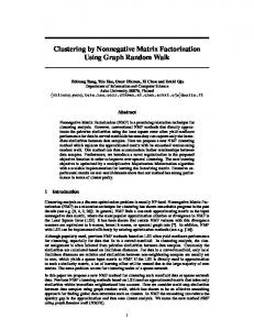
Figure 2:
The proposed method: (a) the design ow, (b) an example.
route, (8) back annotation, and (9) post-layout timing analysis. The input to the design ow is a mixed RTL and gate-level HDL description in Verilog. In the rst step, an HDL-based synthesizer converts the Verilog design description into a hierarchical gate-level netlist by performing HDL compilation and a series of RTL and logic synthesis tasks. In the second step, a timing analysis procedure is applied to perform unitdelay-based timing analysis of the design. A set of critical paths will be identi ed and used to guide the following macro-clustering, oorplanning, and placementand-routing procedures. In the third step, an HDL structural tree of the design is constructed to preserve the design hierarchy. In the fourth step, the system groups small subcircuits to form large macros and decomposes extremely large macros into smaller ones. In the fth step, we use a commercial oorplanner to perform macro oorplanning to determine the locations of hard macros and then extracts the available area for soft macros. In the sixth step, a soft-macro placement procedure is applied to determine the relative location of each soft macro on the layout plane. In the seventh to ninth steps, we use commercial tools to perform placement, routing, back annotation, and post-layout timing analysis. Figure 2(b) illustrates an example. In this example, the HDL design description is rst converted into a structural tree which contains two hard macros HM1 and HM2, and ve soft leaf-macros SM1-SM5. During soft-macro formation, four soft macros SM1, SM2, SM3, and SM4; 5 are formed. After the oorplanning process, a rectilinear area is extracted (dotted-line re-
gion in Figure 2(b)) for soft macros. A soft-macro placement procedure is then applied to determine the relative location of each soft macro based on the criticality and the connectivity between macros. After performing the placement and routing procedures, layout parasitic information is back-annotated and postlayout timing analysis is conducted to identify the most critical signal path, as depicted in Figure 2(b).
3.2 Structural-tree construction
The main objective of the structural-tree construction is to preserve the design structural information from an HDL design description for macro formation. Using an HDL-based design ow, the speci cation of a design is described as a mixed RTL/logic/gate-level description in HDLs such as VHDL and Verilog. An HDL description usually consists of a hierarchy of interconnected modules. During synthesis, each leaf module is synthesized into a gate-level circuit. The nal circuit of the design is a composition of all modules. In our approach, we use a commercial synthesis system to convert a Verilog design description into a hierarchical gate-level netlists. We use an HDL structural tree to represent the structural hierarchy of the Verilog design description. In an HDL structural tree, the root node represents the top design, and each intermediate node represents a module construct. Each leaf node represents a circuit block generated from a leaf module.
3.3 Soft-macro formation
The synthesized subcircuit of each leaf module is naturally a closely-connected cluster. However, a design may also contain extremely large modules containing tens of thousands of gates. This is undesirable in our approach because a large cluster is too rigid for the macro placement and may often result in poor placement results. Furthermore, a design may also contain a large number of small subcircuits. This is also undesirable because when each subcircuit is treated as a soft macro, the computational complexity of the macro-cell placement process will increase and may often result in longer inter-macro wiring. First, we determine the large-macro candidates which need to be decomposed into smaller ones. The selection of large-macro candidates is based on the size of the macros. We de ne the threshold value Mth of a large-macro candidate as: Mth = k � Savg ; cells where Savg is the average macro size ##Total Macros , #Total cells and #Macros are the total number of cells and the number of soft macros in the design, respectively. k is a user-de ned threshold parameter for controlling the size of the large-macro. If a macro is larger than Mth , then it is selected as a large-macro candidate. For each large macro, we use the partitioning method [14] to decompose large macros into smaller clusters. Then we use a clustering algorithm [16] to group small macros into large ones based on the size constraint, and the criticality and connectivity between
macros. Let G = fV; E g be the connected graph where V is the set of macro nodes and E the set of edges. An edge eij exists if there exists at least a signal ow between macros vi and vj . A weight is associated with each edge indicating the number of connections between two corresponding macros. We de ne the connectivity Connij , the criticality Critij , and the closeness Cij of two macros, vi and vj , as below. ( wi +wj ( ) � ( sis+thsj ); sis+thsj � 1; Connij = wi +wj ,2wij si +sj > 1; 0; sth (1) � s i +sj if Crit Path(vi , vj ) and sth � 1; Critij = 1; 0; else; (2) Cij = � Connij + Critij ; (3) where wi denotes the total connection weight of vi , wij denotes the total connection weight between vi and vj , si denotes the size of vi , sth is the upper bound on the size of a cluster set by the user, Crit Path(vi , vj ) denotes that there is a critical path traveling across vi and vj , and � and are two coe�cients set by the user. In order to eliminate small macros and prevent the formation of large clusters, the user can set the upper bound on the size of a cluster. When the size of a new macro formed by merging two macros is larger than the upper bound, the closeness value between these two macros is 0.
3.4 Soft-macro placement
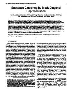
Prior to the soft-macro placement, a oorplanning procedure is invoked to determine the locations of hard macros. Then, the available area for soft macros is extracted, as shown in Figure 3(a) (the dotted area). The main objective of the soft-macro placement is to determine the relative location of each macro on the layout plane. The soft-macro placement consists of two steps: (1) force-directed-based placement and (2) sweepingbased soft-macro assignment. In the rst step, we determine the relative location of each soft macro. In the second step, we assign each soft macro into the layout plane. We divide the layout plane into nine regions, as depicted in Figure 3(a). Initially, each hard-macro is assigned into its corresponding region according to the oorplanning result. Then, we apply the forcedirected algorithm [17] to determine the relative location of each soft macro, as shown in Figure 3(b). Let M = fm1 ; :::; mng be a set of hard and soft macros. Let �xij = jxi , xj j, �yij = jyi , yj j, and �dij = ((�xij )2 +(�xyj )2 ))1=2. Let Fxi (Fyi ) be the total force enacted upon macro i by all the other macros in the x-direction (y-direction). The force equations can be expressed as:
−1
1
X 0
1
HM3
HM1
HM3
HM1
SM1 HM4
Y 0
HM2
SM4
SM2
HM4
HM2 SM3
−1
HM5 HM5 (b)
(a) Y
Window
SM1
(0,0)
SM2
SM1
X SM2
SM4
SM4
SM3 (c)
Figure 3:
Soft-macro placement: (a) oorplanning and soft-macro area extraction, (b) force-directed-based placement, (c) sweeping-based soft-macro assignment.
Fxi = Fyi =
jX =n j =1
x ; (4) (,wij � �xij + r � �xij =�dij ) , Fhm
jX =n j =1
x =[ Fhm
y =[ Fhm
y ; (5) (,wij � �yij + r � �yij =�dij ) , Fhm
jX =m jX =n
(,wij � �xij + r � �xij =�dij )]=m;
j =1 j =m+1 jX =m jX =n
(6) (,wij � �yij + r � �yij =�dij )]=m;
j =1 j =m+1
(7) where m is the number of soft macros. r is the repulsion constant. r is 1 when there is no connection between x and F y are the force acted upon macros i and j. Fhm the set of all soft macros byhmthe hard macros in the xand y-direction, respectively. After computing the forces in both x- and ydirection for each soft macro, we can calculate the relative x- and y-coordinate of each soft macro on the layout plane, as shown in Figure 3(c). We then apply a sweeping-based method to assign soft macros into the available layout area, which is described as below. We rst use a window which sweeps from top to bottom in the y-direction. We then compute the total
required area for the soft macros covered by the window, followed by allocating a region on the available layout area which is large enough to accommodate the soft macros. Since the layout area of each cell can be found in the data book, the total required area for a soft macro is computed as the sum of layout areas of all cells in the soft macro. In our implementation, we use a commercial area router for the detailed routing. According to the vendor's recommendation, we allocate an area of 1.15 times total cell area of a macro to the macro in order to successfully complete the routing. Finally, we assign the soft macros into the allocated region from left to right in the x-direction. The softmacro assignment procedure continues until all the soft macros are assigned to the layout plane. For example, in Figure 3(c), the sweeping window rst covers one soft macro SM1 which is assigned into the top region of the layout plane. In the second sweeping, the window covers two soft macros SM2 and SM4 which will be assigned to the allocated area from left to right. After determining the location of each soft macro, we invoke a number of commercial tools to perform placement, routing, back-annotation, and post-layout timing analysis.
4 Experiments
We have tested the proposed method on three industrial designs. All three designs are described as hierarchical gate-level netlists in Verilog. Table 1 shows the characteristics of the designs in which Nets, IOs, HMs, SMs(Before=After), SMs(Cells=Gates), and Total Gates denote the number of nets, IO pins, hard macros, soft macros before and after performing clustering, cells/gates of soft macros, and total gate-count of the design. In all experiments, we used the TSMC 0.5�m cell library [22]. In addition, we set the threshold values k = 2 for large-macro decomposition and Sth = 0.1 Savg for small-macro clustering. In order to examine the e�ectiveness of our proposed method, we have conducted two sets of experiments, as depicted in Figure 4. In the rst set of experiment, we adapt a commonly used design ow which is described as below. In the rst step, we used Synopsys's Design Compiler [18] to convert the input Verilog design description into a hierarchical gate-level netlist and then performs timing analysis to report the 10 most critical paths. In the second step, we used Cadence's Silicon Ensemble [19] to perform chip oorplanning and determine hard-macros' locations. In the third step, we used Cadence's HLDS tool [19] to perform soft-macro placement. In the fourth step, we used Cadence's Silicon Ensemble [19] to perform detailed placement and routing. In the fth step, the Cadence's HyperExtract [20] was used to extract parasitic information of the layout. In the sixth step, we used AVANT's STAR , DC tool [21] to perform delay calculations and generate an SDF le. Finally, we used Synopsys's Design Time [18] to perform post-layout timing analysis. In the second set of experiments, we used our proposed soft-macro formation method as a pre-processing step to generate soft-macro clusters for the oorplanner. In addition, we used our proposed soft-macro placement method to determine soft-macro
Designs Ind1 Ind2 Ind3
Table 1: Characteristics of the benchmarking designs.
Nets 15,373 27,404 53,344
IOs HMs SMs(Before/After) SMs(Cells/Gates) Total Gates 83 13 157/22 15,086/38,240 75,000 155 8 150/28 42,030/75,361 95,000 73 31 292/50 45,378/124,180 230,000
Table 2: Comparison of the critical delay generated by the design methodology without/with (Method 1/Method 2) our proposed method.
Designs Ind1 Ind2 Ind3
Area(�m) Delay(ns) Method 1 Delay(ns) Method 2 % 5,025�5,025 22.5 18.3 -19 5,300�5,275 47.2 35.9 -24 7,300�7,200 27.6 19.8 -29
locations on the layout plane. For all experiments, we provided the oorplanner (the second step) and the placer-and-router (the fourth step) with the most critical 200, 200, and 400 paths (generated in the rst step) as the timing constraints for ind1, ind2, and ind3, respectively. Table 2 shows the comparison of the design methodology without/with our proposed soft-macro clustering and placement method, in which the delay values are the worst path delays obtained from the post-layout timing analysis. The results show that the design methodology with our proposed method outperforms the one without our proposed method, on an average 24% reduction in the most critical-path delay. Figures 5 and 6 show the most critical path of ind1 generated by without/with our proposed method.
HDL design description Synopsys (Design Compiler)
Structural−tree construction
5 Conclusions
Soft−macro formation
Cadence (Silicon Ensemble)
Cadence (HLDS)
Soft−macro placement
Cadence (Silicon Ensemble) Cadence (HyperExtract) AVANT! (STAR−DC) Synopsys (Design Time)
Chip layout
Figure 4:
The experimental procedure
We have presented a performance-driven soft-macro clustering and placement method by preserving HDL design hierarchy. We have also presented a complete chip design methodology by integrating the proposed method and a set of commercial EDA tools. Experiments on three industrial designs have demonstrated that preserving design hierarchy for soft-macro placement leads to signi cant improvements in circuit timing. This is the rst attempt to investigate the interaction between HDL synthesis, oorplanning, placement, and routing design tasks. There are many open problems need to be solved in order to successfully develop a deep-submicro-based design methodology. The problems include layout-driven HDL synthesis methods, design re nement methods at synthesis, oorplanning, and place-and-route levels, and accurate timing models development to support synthesis tasks.
References
[1] B. T. Preas and M. J. Lorenzetti, Physical Design Automation of VLSI Systems, Benjamin Cummings, Menlo Park, CA., 1988. [2] T. Lengauer, Combinatorial Algorithms for Integrated Circuit Layout, Wiley, 1990. [3] N. Sherwani, Algorithms for VLSI Physical Design Automation, 2nd ed., Kluwer Academic Publishers, 1995.
Figure 5:
The most critical path generated by the design methodology without applying our proposed method. [4] C.J. Alpert and A. B. Kahng, \Recent Direction in Netlist Partitioning: A Survey," INTEGRATION: the VLSI Journal, N19, pp. 1-81, 1995. [5] E. S. Kuh, \Physical Design: Reminiscing and Looking Ahead," Proc. of Int. Symp. on Physical Design, pp. 206, 1997. [6] R. Composano, \The Quarter Micro Challenge: Integrating Physical and Logic Design," Proc. of Int. Symp. on Physical Design, pp. 211, 1997. [7] K. Keutzer, A. R. Newwton, and N. Shenoy, \The future of Logic Synthesis and Physical Design in DeepSubmicron Process Geometries," Proc. of Int. Symp. on Physical Design, pp. 218-223, 1997. [8] R. G. Bushroe et al., \Chip Hierarchical Design System (CHDS): A Foundation for Timing-Driven Physical Design into the 21th Century," Proc. of Int. Symp. on Physical Design, pp. 212-217, 1997. [9] G. Odawara, T. Hiraide and O. Nishina, \Partitioning and placement technique for CMOS gate arrays," IEEE Trans. on Computer-Aided Design, vol.CAD-6, pp.355363, May 1987. [10] Y. C. Wei and C.K. Cheng, \Ratio cut partitioning for hierarchical designs," IEEE Trans. on Computer-Aided Design, vol.CAD-10, pp.911-921, July 1991. [11] S. Dey, F. Beglez and G. Kedem, "Circuit partitioning for logic synthesis," IEEE Journal of Solid-Stage Circuits, vol.26, pp.350-363, March 1991. [12] G. Saucier, D. Brasen, J. P. Hiol, \Partitioning with cone structures," Proc. of Int. Conf. Computer-Aided Design, pp.236-239, 1993. [13] J. Cong and D. Xu, \Exploiting signal ow and logic dependency in standard cell placement," Proc. of Asia
Figure 6:
The most critical path generated by the design methodology with applying our proposed method. and South Paci c Design Automation Conf., pp.399-404, 1995. [14] Y. W. Tsay and Y. L. Lin, \A Row-Based Cell Placement Method That Utilizes Circuit Structural Properties," IEEE Trans. on Computer-Aided Design, vol.14, No. 3, pp.393-397, March 1995. [15] Y.-W. Tsay, W.-J. Fang, Allen C.-H. Wu, and Y.-L. Lin, \Preserving HDL Synthesis Hierarchy for Cell Placement," Proc. of Int. Symp. on Physical Design, pp. 169174, 1997. [16] D. M. Schuler and E. G. Ulrich, \Clustering and linear placement," Proceedings of the 9th Design Automation Conference, pp.412-419, 1972. [17] N. R. Quinn, \The Placement Problem as Viewed from the Physics of Classical Mechanics," Proc. of the 12th Design Automation Conference, pp. 173-178, 1975. [18] \HDL Compiler for Verilog Reference Manual Version 3.4b", Synopsys, 1996. [19] \Silicon Ensemble Reference Manual Version 5.0", Cadence, 1996. [20] \HyperExtract Reference Manual Version 4.0", Cadence, 1996. [21] \STAR-DC Reference Manual Version 2.1.2", AVANT!, 1996. [22] \TSMC ASIC Data Book TCB670", Taiwan Semiconductor Manufacturing Company, Ltd. 1997