communication systems due to its high data rate transmission capability with high ... channel estimation techniques for OFDM communication over frequency selective ..... Simon Haykin, âCommunication systemsâ, John wiley publications, 2010.
K. Elangovan et. al. / International Journal of Engineering Science and Technology Vol. 2(8), 2010, 3483-3493
PERFORMANCE ENHANCEMENT TECHNIQUE FOR OFDM USING CHANNEL ESTIMATION TECHNIQUE K. Elangovan and *Dr. PLK Priyadarsini Research Scholar, *Scientist Center for Research and Development PRIST University, Tanjore - India. ABSTRACT Orthogonal Frequency Division Multiplexing (OFDM) has recently been applied in wireless communication systems due to its high data rate transmission capability with high bandwidth efficiency and its robustness to multi-path delay. Fading is the one of the major aspect which is considered in the receiver. To cancel the effect of fading, channel estimation and equalization procedure must be done at the receiver before data demodulation. Many channel estimation and equalization algorithms are studied in the literatures. This project mainly deals with pilot based channel estimation techniques for OFDM communication over frequency selective fading channels. Mainly three prediction algorithms are used in the equalizer to estimate the channel responses namely, Least Mean Square (LMS), Normalized LMS (NLMS) and Recursive Least Square (RLS) algorithm. These three algorithms are considered in this work and their performances are statistically compared by using computer simulations. 1.Introduction Orthogonal Frequency Division Multiplexing (OFDM) is a multi carrier transmission technique, which divides the available spectrum into many carriers, each one being modulated by a low rate data stream [1]. OFDM is similar to FDMA in that the multiple user access is achieved by subdividing the available bandwidth into multiple channels, which are then allocated to users. However, OFDM uses the spectrum much more efficiently by spacing the channels much closer together. This is achieved by making all the carriers orthogonal to one another, preventing interference between the closely spaced carriers.OFDM is a wideband modulation scheme that is specifically able to cope with the problems of the multi path reception. This is achieved by transmitting many narrowband overlapping digital signals in parallel, inside one wide band. Increasing the number of parallel transmission channels reduces the data rate that each individual carrier must convey, and that lengthens the symbol period. As a result, the delay time of reflected waves is suppressed to within one symbol time. OFDM was found to have total immunity to multi path delay spread provided the reflection time is less than the guard period used in the OFDM signal [2-4]. TDMA partly overcomes this problem by using wider bandwidth channels, which are used by several users. Multiple users access the same channel by transmitting in their data in time slots. Thus, many low data rate users can be combined together to transmit in a single channel that has a bandwidth sufficient so that the spectrum can be used efficiently. There are however, two main problems with TDMA. There is an overhead associated with the change over between users due to time slotting on the channel. A change over time must be allocated to allow for any tolerance in the start time of each user, due to propagation delay variations and synchronization errors. This limits the number of users that can be sent efficiently in each channel. In addition, the symbol rate of each channel is high (as the channel handles the information from multiple users) resulting in problems with multi path delay spread. OFDM overcomes most of the problems with both FDMA and TDMA. OFDM splits the available bandwidth into many narrow band channels. The carriers for each channel are made orthogonal to one another, allowing them to be spaced very close together, with no overhead as in the FDMA. Because of this there is no great need for users to be time multiplex as in TDMA. Thus there is no overhead associated with switching between users [5,6].
ISSN: 0975-5462
3483
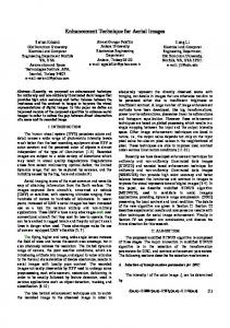
K. Elangovan et. al. / International Journal of Engineering Science and Technology Vol. 2(8), 2010, 3483-3493 The orthogonality of the carriers means that each carrier has an integer number of cycles over a symbol period. Due to this, the spectrum of each carrier has a null name at the center frequency of each of the other carriers in the system. This results in no interference between the carriers, allowing then to be spaced as close as theoretically possible. This overcomes the problem of overhead carrier spacing required in FDMA. In CDMA, the real advantage comes from bandwidth expansion - It might not be suitable for very high bit rates (Like in WLANs). Each carrier in an OFDM signal has a very narrow bandwidth (i.e.1 kHz), thus the resulting symbol rate is low. This result in the signal having a high tolerance to multi path delay spread, as the delay spread must be very long to cause significant inter symbol interference (e.g. > 100 s). 2. BASIC OFDM BLOCK DIAGRAM: The Figure 2.1 shown below is the basic block diagram of the OFDM transmitter and receiver.
Data in
MODULATION (BPSK,QPSK)
SERIAL TO PARALLEL
IFFT
CONVERTER
ADD CYCLIC PREFIX
CHANNEL
AWGN NOISE
Data out DEMODULATION
(BPSK,QPSK)
PARALLEL TO SERIAL
FFT
REMOVE CYCLIC PERFIX
CONVERTER
Fig . 2.1. OFDM Block Diagram
The data to be transmitted on each carrier is to be modulated using any modulation technique depending upon the user requirements. If a single bit is to be transmitted over a modulated symbol BPSK can be used. To transmit two data bits per symbol QPSK can be made use of. In case of transmission of three bits per modulated symbol 8-PSK is used. In binary phase shift keying (BPSK), the phase of a constant amplitude carrier signal is switched between two values according to the two possible signals m1 and m2 corresponding to binary 1 and 0, respectively. Normally, two phases are separated by 180º. If the sinusoidal carrier has an amplitude Ac and energy per bit Eb = 1/2 Ac2Tb, then the transmitter BPSK signal is either. SBPSK(t) = (2Eb/Tb)1/2 cos (2Πfct+θc) or SBPSK(t) = -(2Eb/Tb)1/2 cos (2Πfct+θc)
0