SSD array storage using RAID mechanism. The proposed method enhances the reliability of SSD array. 2% higher than that of existing RAID system and.
Reliability and Performance Enhancement Technique for SSD array storage system using RAID mechanism Kwanghee Park, Dong-Hwan Lee, Youngjoo Woo, Geunhyung Lee, Ju-Hong Lee†, Deok-Hwan Kim* Dept. of Electronic Engineering, Inha University, † Dept. of Computer and Information Engineering, Inha University {khpark, wooyj, dhlee, ghlee}@iesl.inha.ac.kr, {juhong, deokhwan}@inha.ac.kr
Abstract
Currently, most of SSD manufacturers adopt multi level cell (MLC) technology instead of single level cell technology to enlarge the capacity in NAND flash memory. The MLC technology has several disadvantages. First, the life cycle of MLC NAND flash memory is 10,000 and it amounts to only 10% of that of single level cell (SLC) NAND flash memory. Second, the read and write performances of MLC NAND flash memory are slower than that of SLC NAND flash memory [3][4]. Third, MLC NAND flash memory increases the data density in a cell and it causes occurrence of interference so that it reduces the data reliability [5]. Although MLC NAND flash memory has more disadvantages than SLC NAND flash memory, the enlargement of storage capacity becomes important so that most SSD manufacturers prefer to use MLC NAND flash memory inevitably. Besides, it is important to enhance the reliability and performance of SSD based on MLC NAND flash memory since SSD becomes one of major storage systems in nowadays.
Recently solid state drive (SSD) based on NAND flash memory chips becomes popular in the consumer electronics market because it is tough on shock and its I/O performance is better than that of conventional hard disk drive. However, as the density of the semiconductor grows higher, the distance between its wires narrows down, their interferences are frequently occurred, and the bit error rate of semiconductor increases. Such frequent error occurrence and short life cycle in NAND flash memory reduce the reliability of SSD. In this paper, we present reliability and performance enhancement technique on new RAID system based on SSD. First, we analyze the existing RAID mechanism in the environment of SSD array and then develop a new RAID methodology adaptable to SSD array storage system. Via trace-driven simulation, we evaluated the performance of our new optimized SSD array storage using RAID mechanism. The proposed method enhances the reliability of SSD array 2% higher than that of existing RAID system and improves the I/O performance of SSD array 28% higher than that of existing RAID system.
…
B2
B1
A3 A2 A1
A1
A2
A3
AP
1. Introduction
B1
B2
B3
BP
C1
C2
C3
CP
For recent years, as the cost of NAND flash memory becomes lower and the density of NAND flash memory grows higher, the mass-production of solid state drives (SSD) based on NAND flash memory has been launched on a full scale. SSD is strong on shock and its I/O performance is better than that of conventional hard disk drive. SSD is designed using several NAND flash memory chips in parallel and it performs data I/O using interleaving method. Therefore, the performance of SSD is faster than that of single NAND flash memory chip [1][2]. Moreover such SSD design methodology decreases the overhead of garbage collection that performs the erase operation on whole cells of NAND flash memory.
D1
D2
D3
DP
Disk #0
Disk #1
Disk #2
Disk #3
*
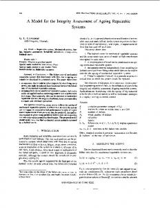
Fig. 1. The Structure of Traditional RAID-4(Dedicated)
Traditionally, RAID (Redundant Array of Independent Disks) has been used to support fast I/O performance and high reliability of storage system. Until now, the array of hard disk drive (HDD) is used to build up RAID systems. Because I/O performance of SSD becomes faster than that of HDD, new RAID scheme adopting the characteristics of SSD need to be surveyed. In this paper, we propose SSD-based RAID
Prof. Deok-Hwan Kim is the corresponding author.
978-1-4244-4522-6/09/$25.00 ©2009 IEEE
140
ISCIT 2009
SSD-based RAID-6 and evaluate the performance of the erasure codes schemes on SSD-based RAID-6.
schemes for improving the performance and the reliability. For supporting high data reliability, as shown in Fig. 1, traditional RAID systems used parity scheme. First, we need to examine what kind of RAID system is adoptable to SSD array storage. Moreover, recently the RAID-6 systems based on hard disk drive that adopting erasure codes such as EVENODD code and Reed-Solomon code for data error detection and data recovery are launched. Second, we analyze the coding schemes appropriate to SSDbased RAID-6 systems and then evaluate their efficiency and complexity. To measure the reliability of RAID based on HDD array, mean time between failures (MTBF) has been used. However, it is not appropriate to only use MTBF to measure the reliability of RAID based on SSD array since several factors such as the life cycle of MLC NAND flash memory, frequently occurred bit errors, and high overhead of error recovery affect the reliability of SSD. Third, therefore, we present new measurement method to correctly evaluate the reliability of RAID based on SSD array. The rest of the paper is organized as follows: In Section 2, we analyze the existing RAID systems. In Section 3, we present heterogeneous RAID-4 and evaluate its performance with respect to several erasure codes via trace-driven simulation. Finally, Section 4 states the conclusion.
2. 1. Heterogeneous SSD-based RAID-4
Disadvantages of the RAID-4 is that the parity device may occur a bottleneck even for small writes since every write operation needs to update a parity disk which is positioned in ones per row. Also, instead of n disk, only n-1 disks are available for servicing reads since the n-th disk does not contain any data except for parity. Table 1. An Example of RAID-4 Workload Frequency of update requests (Sum = 10,000)
A
B
C
P
4,000
5,000
1,000
9,000
Table 1 shows an example of update frequency on existing RAID-4 system. The RAID-4 system consists of information-retained SSDs A, B, C and parityretained SSD P. Each SSD may have different frequency of update requests. In an example of RAID4 workload, we suppose that the frequencies of update requests on SSD A, B, and C are 4,000, 5,000, and 1,000, respectively. Some data can be updated in two or more devices together so that we assume that the frequency of update request on A, B or B, C or A, C or A, B, C is 1,000. Therefore, the frequency of update request on SSD P becomes 9,000 since frequency of common update should be subtracted from total frequencies of update requests. As a result, the frequency of parity-retained SSD is about three times higher than the average frequency of informationretained SSDs. The parity-retained SSD P is much worn out than other information-retained SSDs. As the bit error rate of SSD P becomes higher, the possibility of data corruption increases. Hence, we propose to use the heterogeneous RAID-4 system to overcome this problem.
2. Improvement of SSD–based RAID Systems In SSD based on NAND flash memory, the pattern of occurring errors is irregular and the data content may be incorrect for its read request. Even though MTBF of SSD is much longer than that of HDD, as the SSD becomes antiquated, its disk failure rate and the bit error rate substantially increases. In addition, the reliability of SSD-based RAID system cannot be guaranteed since the standard for criteria of determining SSD failure does not exist. In order to solve this problem, we present three different approaches of improving the data reliability on SSD based RAID systems. First, we propose heterogeneous RAID-4 system to guarantee the reliability of SSD-based RAID by dedicating the frequently updated parity data on HDD. Second, we propose the wear-leveling scheme for SSD-based RAID-5 by distributing all data to multiple SSDs. Finally, we propose to add various erasure codes schemes like Reed-Solomon codes and EVENODD to
… B2 B1 A 3 A 2 A 1
ْ
A1
A2
A3
B1
B2
B3
C1
C2
C3
PC
D1
D2
D3
PD
SSD #1
SSD #2
Parity HDD
SSD #0
Fig. 2. Heterogeneous RAID-4
141
PA PB
If the data update request occurred, the parity stripe P0 is update as well. Therefore, the wear-leveling count of each SSD is decreased one by one. RAID-5 can’t know which data is frequently updated so that the parity’s wear-leveling get confused. Hence, we propose a dynamic parity allocation scheme. It checks the wear leveling of parity stripe in each SSD and selects the best SSD for data update. We construct a k-bit bitmap table for checking wear leveling of parity stripe in RAID-5, where k is the number of SSDs. If the k-bit value of corresponding parity stripe becomes higher than2��� , the location of parity stripe is changed and the parity stripe is moved to the place of having lowest k-bit value wear leveling of parity stripe by greedy approach.
As shown in Fig. 2, the heterogeneous RAID consists of three information-retained SSDs and one parity-retained HDD as the parity-retained storage since the characteristic of parity is write-intensive and SSD is not adaptable to write-intensive storage.
2. 2. The wear leveling scheme for SSD-based RAID-5
As shown in Fig. 3, the RAID-5 uses block-level striping with parity data distributed across all devices. RAID-5 writes are expensive in terms of disk operations and traffic between the disks and the controller. The problem of SSD-based RAID-5 in the case of using RAID-5 system is that the parity stripe is updated more frequently than other stripes. These unbalanced updates shorten the life span of SSD. Because each SSD does not consider the correlation with other SSDs since wear-leveling is done for individual SSD and thus, we need to manage the life span of SSDs. …
B2
B1
k-bit bitma p ta ble (k = 4) SSD #0 SSD #1 SSD #2 SSD #3 P0 0 0 0 0 P1 0 0 1 1 P2 0 0 0 1 P3 1 0 1 1 ••• 0 0 1 1 ••• 0 0 1 0 ••• 1 0 0 0 ••• 1 1 1 1 ••• 1 0 0 1 ••• 0 0 0 1 ••• 1 1 1 1 ••• 0 0 1 0 ••• 1 0 1 1 ••• 0 1 0 0 ••• 1 0 0 1 ••• 0 1 1 1
MSB LSB MSB LSB MSB LSB MSB LSB
A3 A2 A1
SSD #0
A1
A2
A3
AP
B1
B2
BP
B3
C1
CP
C2
C3
DP
D1
D2
C3
Disk #0
Disk #1
Disk #2
Disk #3
SSD #3
A0 A1 A2
P3
B0
B1
P1
B2
C0
P2
C1
C2
P0
D0 D1 D2
2. 3. The Efficiency of Erasure Codes Schemes
Table 2 shows MTBFs and the life cycles of HDD and MLC-based SSD. MTBF is the maximum operating time of a storage device. However, MTBF of SSD doesn’t guarantee the reliability of data since SSD doesn’t have any mechanical components. Therefore, the data corruptions of SSD are hanging over to users. As the amount of entire I/O increases, the life cycle decrease rapidly. So, the life span of SSD should be measured by life cycle per a block than MTBF.
Existing RAID-4 and RAID-5 use the simple parity scheme for fault tolerance of one disk failure whereas RAID-6 uses Reed-Solomon codes scheme or EVENODD coding scheme for fault tolerance of multiple disks failure. 2. 3. 1. Simple Parity. For data reliability, RAID-4 and RAID-5 store two types of data. One is information and the other is parity. A parity block is computed using exclusive OR (XOR) operations of information data on multiple storage devices [6].
Table 2. Comparison of SSD with HDD
HDD 750,000 hrs. None
SSD #2
Fig. 4. Parity placement scheme using k-bit bitmap
Fig. 3. The Structure of RAID-5 (Distributed)
MTBF Life cycle
SSD #1
SSD(MLC) 1,000,000 hrs. 10,000 per a block
n pieces of data Encoding
First of all, the parity stripe becomes hot data quickly since every data update operations are accompanied with parity update. For example, as shown in Fig. 4, four data stripes 0, 1, and 2 were written on first row with parity stripe P0.
�
a parity device
Fig. 5. Encoding Using Simple Parity Scheme
142
n
Fig. 5 shows an example of simple parity scheme of encoding � pieces of data to the parity by XOR operations. Such simple parity scheme is used to recover a certain failed device. If the number of information devices is ��and the space efficiency for information data is � � ���� � �� . The space efficiency increases as the number of information devices increases.
n+m
0
0
0
0
0
1
0
0
0
0
0
1
0
0
0
0
0
1
0
0
0
0
0
1
D1 D2
D1
*
D3
D4
=
D5
D4
C1
D5
B21 B22 B23 B24 B25
C
C2
D
B31 B32 B33 B34 B35
D
D3
D2
B11 B12 B13 B14 B15
Decoding
a failed device
1
C3
Matrix B
�
Fig. 7. Encoding using Reed-Solomon Codes n
a parity device
Fig. 6. Decoding Using Simple Parity Scheme
Fig. 6 shows a decoding example of recovering a failed device with parity device using XOR operations in the case that a certain information device fails. We analyze the complexity of computing parity scheme. When information is newly updated, the corresponding device and the parity device should be updated for parity encoding. Thus the count of XORs operation is two and the complexity is ���� . For encoding or decoding of the simple parity data, simple parity scheme needs � � � XOR operations for � information devices. Thus the complexity is ����. However the simple parity scheme cannot be a best solution since it has a restriction that it cannot recover any failed device in the case of that multiple devices failures.
n+m
1
0
0
0
0
0
1
0
0
0
0
0
1
0
0
0
0
0
1
0
0
0
0
0
1
D1 D2
D1
*
D4
=
D3
D5
D4
B11 B12 B13 B14 B15
C1
D5
B21 B22 B23 B24 B25
C
C2
D
B31 B32 B33 B34 B35
D
D3
D2
C3
Matrix B
(a) 3 nodes fails
2. 3. 2. Reed-Solomon Codes. The most popular and well known erasure code on RAID-6 is Reed-Solomon codes. The R-S codes can recover multiple failures by complicated matrix multiplication. For example, regarding arbitrary � data words and � codes words, R-S codes scheme is able to recover � failures. R-S codes scheme is basically computed on binary words of data and it is composed of w bits, where �� � � � �. Fig. 7 shows the decoding scheme of R-S codes using matrix multiplications. The distribution matrix B is composed of identity matrix (� by � upper side matrix of B) and Vandermonde Matrix (m by � lower side matrix of B ). For encoding the n information retained-SSD and m code-retained-SSD, matrix B is multiplied by data vector D [7]. Fig. 8 shows the decoding process of R-S codes scheme. As shown in Fig. 8 (a), when 3 nodes fail, R-S codes scheme operate to recover the data of failure nodes using a new matrix B�, a new matrix composed by erasing rows corresponding to failed nodes.
0
1
0
0
0
D1
D2
0
0
1
0
0
D2
D3
0
0
0
0
1
D5
D4
C1
B31 B32 B33 B34 B35
D5
C3
B’
D
Survivors
0
0
0
0
1
0
0
0
=
D3
B11 B12 B13 B14 B15
1
0
*
1
0
(b) B � � D � ��������� 0
*
0
0
0
1
0
0
0
D1
0
0
1
0
0
D2
0
0
0
0
1
*
B11 B12 B13 B14 B15
D4
B31 B32 B33 B34 B35
D5
B’ �
D ��
B’-1
(c) B��� � B � D � B� D1 D2 D3
D3
=
D2
=
D
0
0
0
0
0
1
0
0
0
0
0
1
0
0
D3
*
D5 C1
B’-1
C3 Survivors
� ��������� D2
1
0
0
0
0
0
1
0
0
0
0
0
1
0
0
D4 D5
1
D3
*
D5 C1
B’-1
C3 Survivors
(d) D � � B��� � ��������� Fig. 8. Decoding using Reed-Solomon Codes
According to Fig. 8 (b), the multiplication of matrix B� and matrix D result in survivor vector. Therefore, 143
we give an inverse matrix ���� on both terms as shown in Fig. 8 (c), and then data vector D can be recovered by multiplying ���� and survivor vector as shown in Fig. 8 (d). We analyze the complexity of computing R-S codes on RAID-6. The encoding complexity of R-S codes scheme is ���� � since � � D needs �� � �� � � multiplication operations and � � � . The decoding complexity of R-S codes scheme is ���� � since ���� � ��������� needs �� � ��� . Additionally, its update complexity is O(n). Even though R-S codes scheme has high reliability, it requires high computational complexity and lots of write request is required for encoding and decoding of R-S codes scheme since the scheme works on several bytes per unit. Such frequent write operations reduce the life span of SSD.
�� � � � D� � D� which can be regarded as diagonal parities (S is called syndrome). The total number of XORs is nine. EVENODD codes guarantee recoverability when there are no more than two block failures. For instance, we examine a particular failure pattern, when the second and the third data blocks are unavailable as shown in Fig. 10 (b). The syndrome S can be computed by parity blocks as follows: � � �� � �� � �� � ��. Once S is computed, D3 can be recovered as D6 = C3 � D1 � S. Then, D4 can be computed as D� � �� � D� � D� Next, D5 can be computed as D� � D� � � . And finally, D� � D� � D� � �� . All failed blocks are recovered when the decoding process is completed. The total number of XORs is ten.
2. 3. 3. EVENODD. EVENODD coding scheme is the origin of parity array codes as shown in Fig. 9. Many other schemes adopt a similar concept, where data blocks are arranged in a two dimensional parity array and XOR is the only required operation [8][9]. The key advantage of such parity array codes is low computational overhead, which is especially desirable for storage applications.
D1
D3
D5
C1
C3
D2
D4
D6
C2
C4
(a) Encoding
D1
D3
D5
C1
C3
D2
D4
D6
C2
C4
(b) Decoding Fig. 10. Encoding and Decoding using EVENODD code
3. Experimental Results
To evaluate the proposed SSD-based RAID systems, we compared our scheme with existing RAID systems in terms of its life span and reliability. For the experimental environment, we implemented the heterogeneous RAID-4 system and SSD-based RAID5 system with wear-leveling scheme in virtual machine using multi-device open source of a LINUX kernel 2.6.24 environment. We used a benchmark workload that is composed of intensive writing and update requests. The workload is a trace of I/O requests, and every entry is described by I/O time, and I/O type. First, we compared the SSD-based RAID-4 with the heterogeneous RAID-4. Fig. 11 shows the wear rates of the SSD-based RAID-4 using 3 disks and one parity disk and the heterogeneous RAID-4. The result shows that the wear leveling rates of the SSD-based RAID-4 are 2% higher than those of the heterogeneous RAID-4. Fig. 12 shows the experimental result of I/O performance between the SSD-based RAID-5 with proposed dynamic parity allocation scheme and existing asymmetric right RAID-5. The result shows that I/O performance increases when the frequency of
Fig. 9. The Structure of EVENODD
For example, we assume that there are 3 data blocks (n = 3) and 2 parity blocks (m = 2). An EVENODD code is in the form of a �� � �� � �� � �� two dimensional array, where p is a nearest prime number of n. Thus, each block is segmented into �� � �� codes. Fig. 10 shows an example of particular EVENODD code, where � � � and each block is segmented into 2 cells. Fig. 10 (a) shows the encoding scheme of EVENODD codes. The each first parity blocks shown in third column are simply the XOR of data blocks in each row. They can be represented as, �� � D� � D� � D� �� � D� � D� � D� which can be regarded as horizontal parities. The second parity block can be computed as, � � D� � D� �� � � � D� � D� 144
4. Conclusion
read requests increases. It also shows that the performance becomes maximum 28% higher than traditional method when the size of a stripe is between 128KB and 384KB. Data Disk 1 Data Disk 3
4.5 4.0
Unlike conventional HDD, SSD has different characteristics such as limited life cycles, constrained update operation, high electrical bit error rate. Especially, in the case of MLC based SSD, its life cycle is shorter than that of SLC based SSD and its bit error rate is higher than that of SLC based SSD. Our schemes support advanced wear-leveling among array storage by using the appropriate structure of heterogeneous RAID-4 and adoptable erasure codes for SSD-based RAID system. In the future, it is necessary to develop new erasure codes to enhance data reliability of various SSD-based RAID systems. .
Data Disk 2 Parity Disk
Wear Rate(%)
3.5 3.0 2.5 2.0 1.5
ACKNOWLEDGEMENT
1.0
This work was partially supported by a Korea Research Foundation Grant funded by the Korean Government (MEST) (KRF-2008-313-D00822), and the Ministry of Knowledge Economy (MKE) and Korea Industrial Technology Foundation (KOTEF) through the Human Resource Training Project for Strategic Technology, and MIC/ IITA/ ETRI SoC Industry Promotion Center, Human Resource Development Project for IT SoC Architect.
0.5 0.0 SSD-based RAID-4
Heterogeneous RAID-4
Fig. 11. The Comparison RAID-4 systems
References Performance(%)
40.00
[1] Y.-H. Bae, “Design of A High Performance Flash
20.00 0.00 -20.00 -40.00 -60.00
0
10
20
30
[2]
100 90 80 70 60 50 40
[3]
Read request(%)
[4]
The size of stripes(KB)
[5]
Fig. 12 The Performance of SSD-based RAID-5
Besides, Table 3 shows the comparison of the characteristics of RAID-systems. From this result, we can see that SSD-based RAID-6 system using EVENODD codes scheme is appropriate for SSDbased RAID system.
[6]
[7]
[8]
Table 3. Comparison of the Characteristics of RAID Systems The Number Encoding Update Operation of Tolerate Complexity Complexity RAID-4 Simple 1 O(n+1) O(1) (n+1) XOR RAID-5 Simple 1 O(n+1) O(1) (n+1) XOR RAID-6 Multiplication m O(n*m) O(n) (n+m) EVENODD XOR m O(n2) O(n+1) (n+m)
[9]
145
Memory-based Solid State Disk,” KIISE Vol. 25, No. 6, June 2007, pp. 18-28. N. Agrawal et al, “Design Tradeoffs for SSD Performance,” In Proc. of the 2008 USENIX Technical Conference, Boston, Massachusetts, June 2008. Storage Systems Research Center, UCSC, http://www.ssrc.ucsc.edu/proj/reliablefs.html K. Park and J. Yang, J.-H Chang, and D.-H. Kim, “Anticipatory I/O Management for Clustered Flash Translation Layer in NAND Flash Memory,” ETRI Journal, Vol. 30, No. 6, Dec. 2008, pp. 790-798 Channels – Algorithm and Coding, Data Storage System Center, CMU. http://www.dssc.ece.cmu.edu/research/area/3/ D. A. Patterson, G. Gibson, and R. H. Katz, “A case for redundant arrays of inexpensive disks (RAID),” Proc. of ACM SIGMOD, pp. 109-116, June 1988. J. S. Plank, “Erasure Codes for Storage Systems,” Tutorial for USENIX Conference on File and Storage Technologies, San Francisco, CA, December, 2005 M. Blaum, J. Brady, J. Bruck, and J. Menon, “EVENODD: an efficient scheme for tolerating double disk failures in RAID architectures,” IEEE Trans. Computers, Vol. 44, No. 2, Feb. 1995, pp. 192-202 C. Huang, and M. Chen, “On Optimizing XOR-Based Codes for Fault-Tolerant Storage Applications,” Proc. of IEEE Information Theory Workshop (ITW), Sept. 2007, pp. 218-223.