International Journal of Signal and Image Processing Issues Vol. 2016, no. 3, pp. 26-38 ISSN: 2458-6498 Copyright © Infinity Sciences
Performance Evaluation of Interleaved Image Transmission over DCT-MC-CDMA System Abdulmajid F. Al-Junaid1, Faisal S. Al-Kamali2 1 2
Department of Electrical Engineering, Faculty of Engineering and Architecture, Ibb University, Ibb, Yemen Department of Electrical Engineering, Faculty of Engineering and Architecture, Ibb University, Ibb, Yemen Emails:
[email protected],
[email protected].
Abstract- Recently, image transmission takes place as an important research branch in multimedia broadcasting wireless communication systems. Interleaving techniques are required to combat the problems caused by the multipath fading environment in multicarrier code division multiple access (MC-CDMA) system. This paper evaluates the performance of interleaved image transmission over discrete cosine transform MC-CDMA (DCT-MC-CDMA) system with two interleaving techniques, the block interleaving and the chaotic interleaving. Moreover, a parallel interference cancellation (PIC) is used to cancel the multiple access interference from the interleaved received image. Experimental results show a significant performance improvement when applying the interleaving techniques and PIC. Keywords: DCT-MC-CDMA;Block Interleaving; Chaotic Interleaving; PIC.
I. INTRODUCTION Multimedia transmission ofsignals over wireless links is considered as one of the prime applications of recent and future mobile radio communication systems. One of the most important and challenging goal of current and future communication is transmission of high quality images and least error. This is due to the limitations imposed by the wireless communication channels such as fading and multipath propagation. Wireless communications suffer from the intersymbol interference (ISI). ISI caused by interference between two or more versions of the transmitted signal that arrive at the receiver at slightly different times. MC-CDMA system is an attractive technology to deal with the detrimental effects of multipath fading [1]. MC-CDMA system enables efficient frequency domain equalization (FDE) over severe frequency-selective fading channels. However, when system load is high, only using FDE cannot prevent performance degradation, because it still suffers from the multiple access interference (MAI) problem. Hence, it is necessary to employ an interference cancellation scheme such as a parallel interference cancellation (PIC) to improve the performance. Moreover, to combat the burst error problem caused by the multipath fading environment, interleaving techniques are required. In [2], MC-CDMA with different basis functions was investigated. In this paper, a DCT-MC-CDMA system is only considered. In the literature, image transmission over MC-CDMA technology has attracted the attention of several researchers [3, 4]. Ref. [3] presented a study of real-time image traffic over CDMA system was. Furthermore, several coding techniques have been investigated for efficient transmission of images with MC-CDMA over wireless channels [3, 5, 6]. Ref. [7]introduced several interleaving techniques such as block interleaving and helical 26
A. F. Al-Junaid et al. / International Journal of Signal and Image Processing Issues interleaving. A powerful interleaving scheme called Chaotic Baker maps has been proposed for a wide range of applications in communications [8-10], and cryptography [11-13]. In the literature, the issue of combating the effect of the burst error, the ISI and the MAI for DCT-MC-CDMA system has not been studied. This motivated us to do this research. The main contribution of this paper is evaluating the performance of the image transmission over DCT-MCCDMA system with a PIC and two interleaving techniques. Two proposed schemes are suggested and studied in this paper. In the first proposed scheme, the DCT-MC-CDMA signal is interleaved using block interleaving before the transmission to remove the effect of the burst errors. Then, at receiver side, a PIC is used to remove the MAI in addition to the FDE which is used to remove the ISI. In the second proposed scheme, the image is interleaved using a two dimensional chaotic map before the DCT-MC-CDMA modulation. Then, at receiver side, PIC and FDE are used. The remainder of the paper is organized in the following way. The DCT-MC-CDMA system is introduced in Section II. The proposed schemes are presented in Section III. The scheme in [8] is reviewed in Section IV. Experimental results are discussed in Section V. Finally, Section VI presents conclusion.
II. DCT-MC-CDMA SYSTEM A. Definition of the DCT The DCT is a Fourier-related transform similar to the DFT, but it uses only real arithmetic [14]. This paper considers the type-II DCT, because of its large energy compaction property. Unlike the conventional DFT, a single set of cosinusoidal functions cos(2nf t ) is used in the DCT, where n= 0, 1, …, N - 1, f is the subcarrier spacing, and 0 < t < T(T is the symbol period). The bandwidth requirement of the DCT-based system with complex-valued modulation formats is the same as that of the DFT-based system with the same number of subcarriers. However, for a DCT-based system with real-valued modulation formats, one can use single-sideband transmission technology to improve the bandwidth efficiency. In this case, the bandwidth of a DCT-based system can be only half that of the DFT-based system with the same number of subcarriers. After the DCT, sampling the continuous-time signal at time instants𝑇(2𝑛 + 1)/2𝑁 gives a discrete-time sequence [14] X (k )
2 N
N 1
k ( 2n 1) , 2N
( k ) x ( n) cos n 0
where x(n) is the nth sample of the input signal. (0) 1
2
, k 0,...., N 1 .
(1)
and (k ) 1 when k 1,2,...,N 1 .After the
inverse DCT (IDCT), the discrete-time signal can be expressed as follows [14] x(n)
2 N 1 k ( 2n 1) X ( k ) ( k ) cos , N k 0 2N
, n 0,..., N 1 .
(2)
B. Energy Compaction Property of the DCT The DCT is used in several data compression applications, because of the property that is frequently referred to as ‘energy compaction’. Specifically, the DCT of a finite-length sequence often has its coefficients more highly concentrated at the low frequency indices. So, the DCT coefficients at high frequencies can be set to zero without a significant impact on the energy of the signal. More details about the energy compaction property of the DCT are found in [15]. 27
A. F. Al-Junaid et al. / International Journal of Signal and Image Processing Issues
C. DCT-MC-CDMA System Model A schematic block diagram of the baseband downlink DCT-MC-CDMA system is depicted in Fig. 1. We assume a single cell and K active users over a frequency selective channel. At the transmitter, the input data sequence of the kth user is modulated, spreaded and scrambled. The spreading code of each user has a length N. After that, the IDCT is applied. The signal after the IDCT can be represented as follows 𝑑 = 𝐷 −1 𝐶𝑆𝑏
(3)
(a) Transmitter (Base Station)
(b)Receiver (Mobile Unit) Receiver (Mobile Unit)
Figure 1: Structure of the DCT-MC-CDMA system over a frequency selective channel. where 𝐷−1 is the IDCT, C is an NL×NL scrambling code matrix, S is an NL×KL spreading codes matrix, 𝑏 is a KL×1 vector consisting of the modulated symbols of the kth user and L is the number of the transmitted symbols from each user. The structures of the individual components in Eq. 3 are found in [2]. Finally, a cyclic prefix (CP) of NCP chips is added at the beginning of each block to form a transmitted block. At the receiver side, the CP is removed from the received signal and the resulting signal can be formulated as follows 𝑟 = 𝐻𝐶 𝑑 + 𝑛 (4) where 𝐻𝐶 is a circulant matrix. 𝑛 is the noise vector. Eq. 4 can be written in terms of the MAI as follows 𝑟 = 𝐻𝐶 𝑑𝑑𝑒𝑠 + 𝐻𝐶 𝑑𝑖𝑛𝑡 + 𝑛
28
(5)
A. F. Al-Junaid et al. / International Journal of Signal and Image Processing Issues 𝑑𝑑𝑒𝑠
and 𝑑𝑖𝑛𝑡 are given as follows 𝑑𝑑𝑒𝑠 = 𝐷 −1 𝐶𝑆𝑑 𝑏𝑑𝑒𝑠 𝑑𝑖𝑛𝑡 = 𝐷 −1 𝐶𝑈𝑏𝑖𝑛𝑡
(6) (7)
where 𝑏𝑑𝑒𝑠 is an L×1 vector consisting of the desired user’s bits. 𝑑𝑖𝑛𝑡 is an (K-1)L×1 vector consisting of the interfering users’ bits. 𝑆𝑑 is the spreading code of the user of interest. 𝑈 is an NL×(K-1)L matrix consisting of the spreading codes of the interfering users. It is found that in Eq. 5 only the first item contains the desired data. The last item represents the noise. The other item constitutes the interference from other users. The received signal is then transformed into the frequency domain as follows 𝑅 = 𝛬𝐹𝐷 −1 𝐶𝑆𝑏 + 𝑁
(8)
where 𝛬 is a diagonal matrix containing the DFT of the circulant sequence of 𝐻𝐶 . 𝑁 is the DFT of the noise. After that, the FDE, the inverse DFT (IDFT), the DCT, the descrambling, the despreading and the demodulation processes are performed to obtain an estimate of the desired user’s symbols as follows: ̂
𝑏𝑑𝑒𝑠 = 𝑓𝑑𝑒𝑐 (𝑆𝑑𝑇 𝐶 𝐻 𝐷𝐹 −1 𝑊𝑅)
(9)
Where 𝑓𝑑𝑒𝑐 is the decision function. 𝐹 −1 is the IDFT matrix. 𝐷 is the DCT matrix. 𝑊 is the FDE matrix. Note that as Fig. 1 shows, each of the two dashed boxes named as DCT-MC-CDMA Modulator and DCTMC-CDMA Demodulator will be used as one box without interior details in the rest of this paper. Interior details of each box will be mentioned only when it is necessary.
PROPOSED IMAGE TRANSMISSION SCHEMES A. Proposed Scheme with Block Interleaving The proposed scheme with block interleaving is shown in Fig. 2. In addition to the DCT-MC-CDMA system, the proposed scheme with block interleaving contains block interleaving and PIC stages. At the transmitter, a simple block interleaving is performed before transmission. At the receiver, a block de-interleaving is required between the IDFT and the DCT. Also, it is required to perform an interleaving inside the PIC stage between the IDCT and the DFT for the purpose of regenerating the MAI. The purpose of the PIC stage at the receiver is to regenerate and cancel the MAI from the desired user signal.
29
A. F. Al-Junaid et al. / International Journal of Signal and Image Processing Issues
(a) Transmitter (Base Station)
(b)Receiver (Mobile Unit)
Figure 2:Proposed scheme withReceiver block interleaving over DCT-MC-CDMA system with PIC. (Mobile Unit)
Block Interleaving Random channel errors are corrected mostly by error correction codes, but the problem is that wireless channel errors are bursty in nature. The error bursts will largely affect one or more consecutive data symbols. So, it is required to spread error bursts over multiple symbols rather than effecting consecutive symbols. The process of rearranging the order of data symbols to be transmitted so as to spread error bursts over multiple symbols is called interleaving. At the receiver, the original data symbols are restored according to the reverse process which is called de-interleaving. In recent years, several interleaving techniques were considered [7]. Block interleaving is a simple interleaving and it is used in this paper. Block interleaving accepts a set of symbols and rearranges them, without repeating or omitting any of the symbols in the set. The number of symbols in each set is fixed for a given interleaving. The matrix interleaving accomplishes block interleaving by filling a matrix with the input symbols row by row and then sending the matrix contents to the output port column by column.
Parallel Interference Cancellation The structure of the interference cancellation stage for downlink DCT-MC-CDMA system is shown in Fig. 2. It consists of three parts. In the first part, the MMSE equalizer is used to mitigate the effect of frequency-selective channel and gives the initial data estimates of all users. In the second part, the PIC stage is used to regenerate and cancel MAI in frequency domain before equalization. In the third part, the MMSE equalizer is used to provide the estimate of desired user’s data.
30
A. F. Al-Junaid et al. / International Journal of Signal and Image Processing Issues
B. Proposed Scheme with Chaotic Interleaving The proposed scheme with chaotic interleaving is shown in Fig. 3. In addition to the DCT-MC-CDMA system, it contains chaotic interleaving and PIC stages. Chaotic interleaving stage is added before the DCT-MC-CDMA modulator in the transmitter and chaotic de-interleaving process in the receiver is added to reconstruct the original transmitted image.
Chaotic Interleaving Actually, this stage is a 2 dimensions (2D) chaotic Baker map in its discretized version [11-13]. The chaotic Baker map is used in image transmission as an interleaving technique to spread bursts of errors caused by the wireless channels [8-10]. At the same time, the chaotic Baker map adds a degree of encryption to the transmitted image. The chaotic Baker map is an efficient tool to randomize a square matrix of data. Chaotic interleaving constructs permuted sequences with less correlation between their samples.
(a) Transmitter (Base Station)
(b)Receiver (Mobile Unit)
Figure 3:Proposed scheme with Receiver chaotic interleaving over DCT-MC-CDMA system with PIC. (Mobile Unit)
Assuming, the discretized Backer map is denoted by 𝐵(𝑛1,…,𝑛𝑘) , where the vector [𝑛1 , … , 𝑛𝑘 ] denotes the secret key 𝑆𝑘𝑒𝑦 . The secret key 𝑆𝑘𝑒𝑦 is selected so that the integer 𝑛𝑖 divides𝑀 and 𝑀 = 𝑛1 + ⋯ + 𝑛𝑘 , where 𝑀 represents the number of data items in one row. If 𝑀𝑖 = 𝑛1 + ⋯ + 𝑛𝑖 , then the data item with indices(𝑟, 𝑠) , where 𝑀𝑖 ≤ 𝑟 < 𝑀𝑖 + 𝑛𝑖 , and 0 ≤ 𝑠 < 𝑀 is mapped to [11-13]:
31
A. F. Al-Junaid et al. / International Journal of Signal and Image Processing Issues
𝑀
𝑀
𝑛𝑖
𝑛𝑖
𝑛𝑖
𝑀
𝐵(𝑛1,…,𝑛𝑘) (𝑟, 𝑠) = ( (𝑟 − 𝑀𝑖 ) + 𝑠 mod ( ) ,
𝑀
(𝑠 − 𝑠 mod ( )) + 𝑀𝑖 ) 𝑛𝑖
(10)
For a square matrix having dimensions of 𝑀 𝑥 𝑀 , the steps of chaotic process are performed as follows [10]: 1) The matrix is divided into 𝑀 rectangles and each rectangle has a width 𝑛𝑖 and contains 𝑀 number of elements. 2) The elements of each rectangle are rearranged as one row in the target randomized matrix. Rectangles are arranged as right one goes to the top and left one goes to the bottom of the target randomized matrix, beginning with upper rectangle then lower rectangle. 3) Scanning elements inside each rectangle begins from the bottom left corner element towards upper element.
III. SCHEMEIN [8] For comparison purpose, the scheme in [8] (chaotic interleaving with MMSE equalizer scheme) is simulated for downlink DCT-MC-CDMA system. Fig. 4 shows the structure of such scheme. The difference between the proposed scheme with chaotic interleaving and the scheme in [8] is that the proposed scheme uses a PIC to cancel the effect of the MAI. On the other hand the impact of the MAI is not taken into account in [8]. Moreover the scheme in [8] was applied for the conventional DFT based MC-CDMA system and not for the recent DCT-MCCDMA system. For fairly comparison, in this paper, the scheme in [8] is applied for the DCT-MC-CDMA system.
(a) Transmitter (Base Station)
(b)Receiver (Mobile Unit) Figure 4:Structure of Scheme Receiver (Mobile Unit) in [8].
IV. SIMULATION RESULTS The quality of the reconstructed image compared to the original transmitted image is measured using two metrics MSE and PSNR. The MSE is defined as follows [3, 4]: 2
𝑀𝑆𝐸 =
𝑀 ∑𝑀 𝑖=1 ∑𝑗=1(𝐼𝑜 (𝑖,𝑗)−𝐼𝑟 (𝑖,𝑗))
𝑀2
32
(11)
A. F. Al-Junaid et al. / International Journal of Signal and Image Processing Issues where 𝑀2 is total number of pixels in the transmitted image, 𝐼𝑜 and𝐼𝑟 are the original and the recovered images, respectively. The PSNR is defined as the ratio between the maximum possible power of a signal and the power of the corrupting noise that affects the fidelity of this signal. The PSNR can be expressed as [3, 4] 2 𝑓𝑚𝑎𝑥 ) 𝑀𝑆𝐸 2
𝑃𝑆𝑁𝑅 = 10 𝑙𝑜𝑔 (
(12)
where 𝑓𝑚𝑎𝑥 is the maximum pixel value in the image.
A. Simulation Parameters More details of the simulation parameters are given in Table 1. The users are assumed to be transmitting at equal power. Table 1: Simulation Parameters. Modulation
Binary phase shift keying
Spreading Codes
Walsh-Hadamard code with N=16.
Number of Users
K=10
Number of Symbols
L=8
DFT points
128
Cyclic Prefix Length
NCP =16
Wireless Channel Type
Vehicular A channel [16]
Equalization
MMSE
Channel Estimation
Ideal
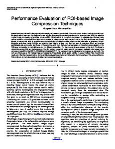
B. PSNR and MSE Performance In the first experiment, the Lena image has been transmitted and received with the MMSE scheme, the scheme in [8], and the two proposed schemes for half load users (K=8). The PSNR and MSE values for different values of SNR (0-30dB) were recorded for all schemes. Fig. 5 shows the PSNR versus SNR for the Lena image transmission with the proposed schemes, the scheme in [8] and the MMSE scheme when K=8. This figure shows that the PSNR for all schemes increases with increasing of SNR. There is a good improvement in PSNR at high SNR values for the two proposed schemes over the MMSE scheme and the scheme in [8]. The PSNR values for all schemes are equal at low SNR (SNR ≤ 5dB) because the noise here is dominant not the interference. At high SNR, the improvement happened by the two proposed schemes because the interference is the dominant at high SNR and the MAI canceller (PIC) can work well in this region. The proposed scheme with chaotic interleaving has the best performance over the other schemes. Approximately, this improvement happened for most values of SNR (SNR ≥ 5dB) which shows the ability of chaotic interleaving to combat the effect of the burst error which resulted from the high noise. In addition, 33
A. F. Al-Junaid et al. / International Journal of Signal and Image Processing Issues the proposed scheme with chaotic interleaving combines PIC, chaotic interleaving, and MMSE equalizer which combat the effects of MAI, burst errors and ISI, respectively. The chaotic interleaving is considered as an interleaving technique and also adds a degree of security to the transmitted images.
Figure 5:PSNR versus SNR for the image transmission with the proposed schemes, the scheme in [8], and the MMSE only at K=8.
Figure 6:PSNR versus SNR for the image transmission with the proposed schemes, the scheme in [8], and the MMSE only at K=16.
In the second experiment, the Lena image has been transmitted and received with the MMSE scheme, the scheme in [8], and the two proposed schemes for full load users (K=16). The PSNR and MSE values for different values of SNR (0-30dB) were recorded for all schemes. Fig. 6 shows the PSNR versus SNR for all tested schemes 34
A. F. Al-Junaid et al. / International Journal of Signal and Image Processing Issues when K=16. In general, the improvement in PSNR performance of two proposed schemes over other schemes at full load users is better than half load users. This reveals the good ability of PIC to regenerating and canceling MAI from the desired user for large number of users (K=16). Also, the proposed scheme with chaotic interleaving has the best performance over all schemes. The MSE vs. SNR for all tested schemes are shown in Fig. 7 (half load users K=8) and Fig. 8 (full load users K=16). As these figures show, the MSE for all schemes decreases with increasing of SNR. In general, there is a similarity between MSE performance improvement and PSNR performance improvement for all tested schemes when the load of users is half and full.
Figure 7:MSE versus SNR for the image transmission with the proposed schemes, the scheme in [8], and the MMSE only at K=8.
Figure 8: MSE versus SNR for the image transmission with the proposed schemes, the scheme in [8], and the MMSE only at K=16.
35
A. F. Al-Junaid et al. / International Journal of Signal and Image Processing Issues
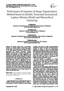
C. Clarity Investigation In the previous subsection, the PSNR and MSE metrics are used to measure the quality of the reconstructed image compared to the original transmitted image for the tested schemes. The visual quality of the reconstructed images compared to the original transmitted images is also important to be demonstrated. The received images of one downlink user at SNR value 15 dB are shown in Fig. 9 for the MMSE scheme (b), the scheme in [8] (c) , the proposed scheme with block interleaving (d), and the proposed scheme with chaotic interleaving (e). By comparingthese received images to the original image in Fig. 9 (a), we can conclude the superiority of our proposed schemes over the conventional MMSE equalizer and scheme in [8].
(a)
(b)
(c)
(d)
(e)
Figure 9:Received Images from different schemes at SNR =15dB and K=16 (a)Original Image (b)MMSE only (c) Scheme in [8] (d)Proposed scheme with Block Interleaving (e) Proposed scheme with Chaotic Interleaving
36
A. F. Al-Junaid et al. / International Journal of Signal and Image Processing Issues
V. CONCLUSION In this paper, the performance of two proposed image transmission schemes for downlink DCT-MC-CDMA system has been evaluated and compared to the performance of traditional MMSE scheme and the recent scheme in [8]. Two interleaving techniques were used to combat the problems caused by the multi-path fading environment in multicarrier code division multiple access (MC-CDMA) system. To remove the effect of the burst errors, the first proposed scheme uses the block interleaving before the transmission and the second proposed scheme uses the chaotic interleaving before the DCT-MC-CDMA modulation. The two proposed schemes use a PIC at the receiver to regenerate and cancel the MAI from the received image. Simulation results demonstrated a significant performance improvement in terms of PSNR and MSE values when applying the proposed schemes. The proposed scheme with chaotic interleaving has the best performance over all schemes. The chaotic interleaving also adds a degree of security to the transmitted images.
REFERENCES [1]L. Hanzo, L. Yang, E. Kuan, and K. Yen.Single and Multi-Carrier DS-CDMA: Multi-User Detection, Space-Time Spreading, Synchronisation, Networking and Standards, John Wiley & Sons, Inc., 2003. [2]F. S. Al-kamali, H. M. Al-qasem, B. A. Saif, K. K. Albhloli, and N. A. Suliman.Multi-Carrier CDMA System With Different Basis Functions. Journal of Communications Engineering and Networks.Vol. 1, No. 1, pp. 1926, Oct. 2013. [3]P. P. Dang, and P. M Chau.Robust image transmission over CDMA channel.IEEE Trans. on Consumer Electronics,Vol. 46, No. 3, 2000. [4]T. Kathiyaiah and T. H Oh.Performance analysis of JPEG2000 transmission through low SNR MC-CDMA Channel.In Proc. of IEEE 9th international conference on communications, Malaysia 2009, p. 15–17. [5]J. K. Rogers and P. C. Cosman.Wavelet zerotree image compression with packetization.IEEE Signal Processing Letters, Vol. 5, No. 5, pp. 105–107, 1998. [6]J. G. Proakis.Digital communications, 3rd edition. New York: McGraw-Hill, 1995. [7]Y. Q. Shi, X. M. Zhang, Z. C Ni and N. Ansari.Interleaving for combating bursts of errors.In IEEE circuits and systems magazine,Vol. 4. First Quarter, 2004. [8]E. M. El-Bakary, E. S. Hassan, O. Zahran, S. A. El-Dolil and F. E. Abd El-Samie.Efficient Image Transmission with Multi-Carrier CDMA.Wireless Pers. Commun.,Vol. 69, pp. 979-994, 2013. [9]B. Jovic, C.Unsworth. Chaos-based multi-user time division multiplexing communication system .IET Communications,Vol. 1, No.4, pp. 1751–8628, 2007. [10]E. S. Hassan,S. E. El-Khamy, M. I. Dessouky, S. A. El-Dolil , & F. E. Abd El-Samie. Chaotic Interleaving scheme for continuous phase modulation based single-carrier frequency-domain equalization systems.Wireless Personal Communications,Vol. 62 No. 1, pp. 183–199, 2012. [11]R. Matthews.On the derivation of a chaotic encryption algorithm.Cryptologia XIII,Vol. 1, 1989. [12]Fridrich J. Symmetric ciphers based on two-dimensional chaotic maps.International Journal of Bifurcation and Chaos,Vol. 8, pp. 1259–1284, Oct. 1998. [13]F. Han, X. Yu, and S. Han.Improved baker map for image encryption.In ISSCAA2006, p.1273–1276. [14]P. Tan, and N. C. Beaulieu.A Comparison of DCT-Based OFDM and DFT-Based OFDM in Frequency Offset and Fading Channels.IEEE Trans. Commun., vol. 54, no. 11, pp. 2113-2125, Nov. 2006.
37
A. F. Al-Junaid et al. / International Journal of Signal and Image Processing Issues [15]A. V. Oppenheim, R. W. Schafer, and J. R. Buck.Discrete-Time Signal Processing, 2nd edition, Prentice Hall,1999. [16]3rd Generation Partnership Project, 3GPP TS 25.101 – Technical specification group radio access network;user equipment (UE) radio transmission and reception (FDD) (Release 7),Section B.2.2, Sep. 2007.
38