Very high bit rate Digital Subscriber Lines (VDSL) [1, 2] is the latest digital subscriber line technique for high speed communication on twisted copper wires.
Performance evaluation of the Zipper duplex method Frank Sjöberg†, Mikael Isaksson�, Petra Deutgen†, Rickard Nilsson†, Per Ödling†, and Per Ola Börjesson† †
Luleå University of Technology, Division of Signal Processing, SE-971 87, Luleå, Sweden � Telia Research AB, Aurorum 6, SE-977 75, Luleå, Sweden
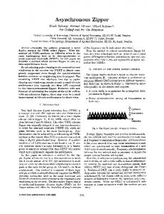
Abstract In this paper we present performance results for a new duplex scheme, called Zipper, for DMT-based VDSL systems on copper wires. This scheme divides the available bandwidth by assigning different subcarriers for the upstream and downstream direction. It has high exibility to divide the capacity between the up- and downstream as well as good coexistence possibilities with other systems such as ADSL. Simulation results show high bitrate performance in different environments such as mixed ADSL and VDSL traf
c, under radio frequency interference, and with different background noise sources. I.
Introduction
Very high bit rate Digital Subscriber Lines (VDSL) [1, 2] is the latest digital subscriber line technique for high speed communication on twisted copper wires. VDSL is intended to use larger bandwidth and achieve higher bit rates than its precursor, e.g. Asymmetrical Digital Subscriber Line (ADSL) [3] and High bit rate Digital Subscriber Line (HDSL) [4]. The standard for VDSL is currently being developed and is discussed in forums such as American National Standards Institute (ANSI) and European Telecommunications Standards Institute (ETSI). A signi
cant problem VDSL systems confront is near-end crosstalk (NEXT). This NEXT occurs when data is transmitted simultaneously in both directions, on the same frequencies, and on several wires in the same binder group. Systems that predominantly transmit in only one direction (such as ADSL) experience mostly far-end cross-talk (FEXT), a markedly less severe problem than NEXT [5]. Avoidance of NEXT by dividing the channel capacity between the two directions has shaped the existing VDSL proposals. Time division duplex (TDD) [6] and frequency division duplex (FDD) [7] are two different proposals for dividing the capacity in time and in frequency, respectively. Recently we introduced a novel discrete multi-tone (DMT)-based [8] duplex scheme for VDSL, called Zipper [9]. Zipper uses different orthogonal sub-carriers in the upstream and downstream directions to divide the capacity, thereby avoiding NEXT. Using several orthogonal signals gives Zipper both variable capacity allocation and high ADSL compatibility.
Upstream Downstream
Frequency Figure 1 The Zipper principle of capacity division.
In this paper we evaluate the performance of the Zipper duplex method. We calculate achievable bit rates for different scenarios consisting of different types of wires and noise sources. In particular we consider Zipper performance in a VDSL only environment, in mixed VDSL and ADSL traf
c, and with ETSI models for background noise and radio frequency interference (RFI). II.
The Zipper Duplex Method
Zipper extends traditional DMT in two ways: � it uses different DMT-carriers in different transmission directions (as shown in Figure 1) and � it adds a cyclic suffix (CS) to ensure orthogonality between the transmitted and received signal (as shown in Figure 2). Zipper allocates different sub-carriers for the upstream and the downstream. A sample allocation scheme is sketched in Figure 1. The allocation of the upstream and downstream sub-carriers can be done dynamically enabling runtime adaption of the bit rates. The upstream part of a transmitted DMT frame can be modeled as: ! P j 2� kf s t Re Xup [k ] e 2N t∈[0, 2N +CfPs +C S ] xup (t) = k ∈Iup 0 otherwise, (1) where Iup is the index set for the upstream carriers, N is the total number of sub-carriers, CP is the length (in samples) of the cyclic pre
x, CS is the length of the cyclic suffix and fs is the sampling frequency. Similarly the downstream part of the DMT frame has an index set Idown that is complementary to Iup (or a subset thereof).
a b c d
a -10
∆ Desired signal + NEXT signal =
CP
CS
-20 Power Spectral Density (dB)
CP
CS
Received signal ∆+CP/fs
∆+(CP+2N)/fs
Received signal 9-NEXT on other carriers 9-FEXT disturbing received signal 9-NEXT disturbing received signal
t
-30 b
-40
d d
-50
CS = 0 CS = 25
c -60
d CS = 50
Amplitude
Figure 2 Timing diagram showing the NEXT symbol frame, the desired symbol frame, and the portion of data extracted from the received frame.
NEXT impulse response
Cable inpulse response
hNEXT(t)
hcable(t)
-70
-80
0
1
2
3
4 5 6 Frequency (MHz)
7
8
9
10
Figure 4 Level of NEXT that appear if a too short cyclic suffix is used.
pressed as: r (t) = xup (t) � hcable (t) + xdown (t) � hNEXT (t) , ∆
∆+CP/fs
t
Figure 3 Superimposed channel impulse response from NEXT and desired signal.
Because Zipper transmits and receives simultaneously, the two network ends must be synchronized in both time and frequency in order to maintain orthogonality. As both the upstream and the downstream contribute to a received DMT frame, time synchronization is required to keep the signal contributions within one DMT frame. All transmitters in the access network (that may cause interference to each other) are synchronized to transmit simultaneously. Frequency synchronization between the two network ends is necessary to ensure the proper spacing between sub-carriers. However, in addition to synchronizing the transmitters and receivers, we add a cyclic suffix to ensure orthogonality between the upstream and downstream signals, thus preventing NEXT and near echoes. Traditional DMT uses a cyclic pre
x to preserve orthogonality between the carriers and prevent interblock interference [10], but Zipper adds an extra cyclic suffix to preserve orthogonality between the upstream and downstream carriers. Consider a network terminal. With the Zipper scheme, it simultaneously transmits and receives. So the network terminal is not only receiving its intended signal but also NEXT from nearby transmitters plus its own transmitted signal which appears as near echoes. In Figure 3 we sketch a NEXT impulse response together with the cables impulse response. The desired signal is delayed � seconds due to the propagation delay, but the disturbing signal arrives almost immediately. The NEXT impulse response could also represent a near echo impulse response. A received signal at the central office can be ex-
(2)
where we have included only one NEXT disturber. The disturbing signal in (2) could also represent near echoes. Since the desired upstream signal is delayed, the fast Fourier transform (FFT) in the DMT receiver will use the part of the received signal, r (t), that is in the range � � CP + 2N CP , ,�+ t∈ �+ (3) fs fs as depicted in Figure 2. For the non-delayed disturbing downstream signal to be orthogonal it needs to be cyclically extended so that it spans the whole range in (3). This is accomplished by using a cyclic suffix that is equal to or longer than the propagation delay �. Since there can be wires of different length in an access network, the cyclic suffix has to be as long as the delay in the longest wire-pair. Figure 4 shows how much NEXT is suppressed by a cyclic suffix of different lengths. For this case a cyclic suffix of 60 samples would have completely suppressed the NEXT. To summarize this section, Zipper is a DMT-based system transmitting orthogonal signals over different sub-carriers in different transmission directions. Maintaining signal orthogonality at the receiver end puts two key system requirements: � synchronization among all transmitters at both ends � a cyclic suffix to compensate for propagation delay III.
Flexibility and Compatibility
Zipper is very exible duplex scheme. This is because it uses a large number of sub-carriers to divide the capacity and these sub-carriers can be assigned dynamically (even after the system is installed and running). This gives the advantage that any desired ratio between up and downstream
upstream
Table 1. Simulation parameters.
downstream
Simulation AWGN System margin Coding gain SNR-gap Sampling frequency Used bandwidth Number of carriers Length of CP Length of CS
Arbitrary transmission direction
10-20 MHz
2 MHz
0.1 MHz
Figure 5 A Zipper subcarrier assignment demonstrating possible coexistence with ADSL.
bit rates can be chosen at any time. The exibility in subcarrier assignment also allows a Zipper based VDSL system to be spectrally compatible with other systems. A valuable feature for VDSL systems is the ability to coexist in the same binder group as other systems, such as ADSL. A reasonable condition for coexistence between ADSL and VDSL is that neither system introduces NEXT to the other. This can be achieved if the both ADSL and VDSL transmit in the same direction in the common frequency band. With Zipper the lowermost sub-carriers, those where ADSL exists (under 2.0 MHz), may be partitioned such that only FEXT is introduced between ADSL and VDSL [11], as depicted in Figure 5. IV.
bk = log2
�
�
SN Rk � code +1 , � margin
where SN Rk is the signal to noise ratio on carrier k , code is the coding gain, is the SNR-gap1 between the Shannon capacity and QAM-modulation [13], and margin is the system margin. System margin is the additional amount of noise the system can tolerate without exceeding the allowed bit error rate (BER). By summing the number of bits given by the bitloading we get the capacity of the system. Within the VDSL frequency band there are certain frequency bands reserved for amateur radio users [2], so called HAM-bands. To comply with the regulations for usage of these bands we are not allowed to transmit within these bands. So the carriers that correspond 1 An
10
7.
60 TP2-cable TP1-cable 50
bit rate (Mbps)
40
SNR-gap of 9.8 dB [13] is used to achieve a BER of approximately
30
20
Performance evaluation
We have calculated the bit rate performance of Zipper for four different background noise environments. The
rst case is a clean VDSL scenario with only AWGN as background noise. The second case consists of a mix of ADSL and VDSL services generating ADSL crosstalk in addition to the AWGN. The third and fourth cases use the ETSI background noise model [2], while the fourth case also includes radio frequency interference (RFI). All four cases include VDSL self-FEXT from 25 other users. Since Zipper uses DMT-modulation it is the bit-loading [12] that determines the bit rate of the system. The number of bits that can be loaded onto carrier number k is calculated as [12]
parameters 140 dBm/Hz
margin = 6 dB
code = 3 dB = 9.8 dB 22 Mhz 300 kHz - 11 MHz 2048 100 samples 220 samples (2000 m)
10
0 0
200
400
600
800 1000 1200 wire length (m)
1400
1600
1800
2000
Figure 6 Achievable downstream (8:1) asymmetrical bitrates, with AWGN and 25 self-FEXT distubers.
to frequencies in the HAM-bands are not loaded with any bits. Achievable bit rates have been calculated for different lengths of TP1 and TP2 wires [1], for a target BER of 10 7 . The TP1 wire has a diameter of 0.4 mm and the TP2 wire has a diameter of 0.5 mm. Parameters used in the calculation are listed in Table 1.
A.
VDSL Environment
Figure 6 shows achievable (8:1) asymmetrical bit rates versus wire length for the case with only self-FEXT and AWGN as background noise. For wires shorter than 600 m there is no big difference between the two type of cable, but for longer wires the thicker TP2 cable gives higher bit rates. This is because self-FEXT is the dominating noise source for shorter wires and AWGN for longer wires. The TP2 wire attenuates the signal less than TP1, thus it attenuates FEXT less also, which gives almost the same SNR for both types of wire for shorter lengths.
60
60 TP2, ADSL-compatible TP1, ADSL-compatible TP2, not ADSL-compatible TP1, not ADSL-compatible
50
TP2-cable TP1-cable 50
40 bit rate (Mbps)
bit rate (Mbps)
40
30
20
20
10
0 0
30
10
200
400
600
800 1000 wire length (m)
1200
1400
0 0
1600
200
400
600
800 1000 wire length (m)
1200
1400
1600
Figure 7 Achievable (8:1) asymmetrical downstream bit rates for Zipper, with 25-ADSL systems and 25 self-FEXT.
Figure 8 Downstream (8:1) bit rates, with ETSI background noise model A and 25 self-FEXT.
B.
signal power of -60 dBm and the other
ve have -40 dBm signal power. The signal powers at the central office are 10 dB lower. To suppress this RFI we have used a time window [14] at the receiver. To preserve the orthogonality after the windowing each DMT-frame is extended cyclically by 60 extra samples. Figure 9 show the performance for this case and Figure 10 shows the spectrum of the ETSI background noise plus the RFI signals at the customer location (after window and FFT). The bit rate performance showed to be just slightly lower than with only the ETSI noise model. Table 2 shows the maximum length the wires can have for certain bit rates (both symmetrical and asymmetrical), for all different noise scenarios.
Mix of VDSL and ADSL
The results for the second case, where Zipper coexists with 25 ADSL users in the same binder group, are shown in Figure 7. The crosstalk models and ADSL spectral power mask are speci
ed by ANSI in [1]. To make Zipper compatible with ADSL the lower sub-carriers are assigned as shown previously in Figure 7. Figure 7 also shows the results for a case where the sub-carrier assignment is made in such a way that the two systems are not spectrally compatible (every ninth sub-carrier is used in the upstream direction). We can see that there is a clear advantage in making VDSL spectrally compatible with ADSL. But even when we avoid NEXT from the ADSL systems the performance is lower than in a clean VDSL-environment. This is because the power spectral density of the ADSL signal is 20 dB higher than for VDSL, so FEXT from ADSL will be much stronger FEXT from VDSL in the common frequency band. ETSI noise model
With the ETSI background noise model A de
ned in [2] we get the performance shown in Figure 8. The ETSI noise model includes AWGN and a mix of crosstalk from other existing services such as ADSL, HDSL, ISDN, etc. Comparing with Figure 7 we see that the performance with the ETSI model is not much different than the performance for the ADSL case. This is not completely unexpected since the power spectral density of the ETSI noise model resembles that of an ADSL system. D.
TP2-cable TP1-cable
ETSI noise model plus RFI
As a worst case scenario we have added 8 broadcast radio interferers to the ETSI noise model A. These 8 RFI signals are those speci
ed by ETSI [2] except for the two below 300 kHz. At the customer side, three of the RFI signals have
50
40 bit rate (Mbps)
C.
60
30
20
10
0 0
200
400
600
800 1000 wire length (m)
1200
1400
1600
Figure 9 Do wnstream (8:1) bitrates, with ETSI background noise model A plus RFI and 25 self-FEXT.
131R2, ANSI, Sacramento, CA, Sept. 1997.
-60
[2] Very high speed digital subscriber line (VDSL); part1: Functional requirements, Tech. Rep. DTS/TM060031(draft), ETSI-TM6, Nov. 1997.
-70
Power spectral density (dBm/Hz)
-80
[3] K. Sistanizadeh, P. Chow, and J. Cioffi, Multitone transmission for asymmetric digital subscriber lines (ADSL), in Proc. Intern. Conf. Commun., pp. 756760, May 1993.
-90
-100
[4] J. Lechleider, A review of HDSL progress, IEEE J. Select. Areas Commun., vol. 9, pp. 769784, Aug. 1991.
-110
-120
[5] J.-J. Werner, The HDSL environment, IEEE J. Select. Areas Commun., vol. SAC-9, pp. 785800, Aug. 1991.
-130
-140
-150
0
200
400
600
800
1000 1200 Subcarrier index
1400
1600
1800
2000
Figure 10 Power spectral density of ETSI noise model A plus RFI. Table 2. Reach for different background noise scenarios. bit rate Reach in meters for TP1/TP2 -wire (Mbps) AWGN ADSL-mix ETSI ETSI+RFI 52:6.4 160/160 110/110 130/130 120/120 26:3.2 860/1050 760/900 750/900 690/830 13:1.6 1330/1630 1060/1310 1050/1310 1000/1240 26:26 270/270 180/180 200/200 190/190 13:13 930/1130 800/970 790/990 730/900
It should be noted that HAM-radio interferers can be much stronger than the broadcast interferers used in this case, but they can be almost completely cancelled with RFIcancellation methods such as [15], [16]. V.
Conclusions
Zipper is a duplex method for VDSL that is very exible due to the many sub-carriers that divides the capacity between the up- and downstream direction. This allows Zipper to be spectrally compatible with other existing systems, such as ADSL. In this paper we have evaluated the performance of the Zipper duplex scheme. We showed that it gives good bit rate performance in coexistence with ADSL systems. The scheme is also shown to be robust against RFI. The best performance is obtained in an environment with only VDSLsystems due to the decreased level of crosstalk. VI.
Acknowledgment
The authors wish to thank Paul Petersen and Sarah Kate Wilson for their help and comments on this paper. References [1] Very-high-speed digital subscriber lines system requirements, draft technical report, Tech. Rep. T1E1.4/97-
[6] J. M. Cioffi, J. S. Chow, J. A. Bingham, and P. Tong, An SDMT line code proposal with rationale for support, Tech. Rep. T1E1.4/96-088, ANSI, Colorado Springs, Co, Apr. 1996. [7] C. Fadel et al., Preliminary proposal for a single-carrier VDSL speci
cation, Tech. Rep. T1E1.4/97-106, ANSI, Austin, Tx, Feb. 1997. [8] J. A. Bingham, Multicarrier modulation for data transmission: An idea whose time has come, IEEE Commun. Mag., vol. 28, pp. 514, May 1990. [9] M. Isaksson, P. Deutgen, F. Sjöberg, P. Ödling, H. Öhman, S. K. Wilson, and P. O. Börjesson, Zipper a exible duplex scheme for VDSL, in Proc. Intern. Workshop on Copper Wire Access Systems, (Budapest, Hungary), pp. 9599, Oct. 1997. [10] A. Peled and A. Ruiz, Frequency domain data transmission using reduced computational complexity algorithms, in Proc. IEEE Int. Conf. Acoust., Speech, Signal Processing, (Denver, CO), pp. 964967, 1980. [11] D. Bengtsson, P. Deutgen, N. Grip, M. Isaksson, L. Olsson, F. Sjöberg, and H. Öhman, Zipper performance when mixing ADSL and VDSL in terms of reach and capacity, Tech. Rep. T1E1.4/97-138, ANSI, Clearwater Beach, Florida, May 1997. [12] P. S. Chow, J. M. Cioffi, and J. A. C. Bingham, A practical discrete multitone transceiver loading algorithm for data transmission over spectrally shaped channels, IEEE Trans. Commun., vol. 43, pp. 773775, Feb. 1995. [13] G. Forney and M. Eyuboglu, Combined equalization and coding using precoding, IEEE Commun. Mag., vol. 29, pp. 2534, Dec. 1991. [14] P. Spruyt, P. Reusens, and S. Braet, Performance of improved DMT transceiver for VDSL, Tech. Rep. T1E1.4/96104, ANSI, Colorado Springs, Co, Apr. 1996. [15] B. Wiese and J. Bingham, Digital radio frequency cancellation for DMT VDSL, Tech. Rep. T1E1.4/97-460, ANSI, Sacramento, CA, Dec. 1997. [16] F. Sjöberg, R. Nilsson, N. Grip, P. O. Börjesson, S. K. Wilson, and P. Ödling, RFI supression in DMT-based VDSL systems, to appear at Intern. Conf. on Telecomm. 98, (Chalkidiki, Greece), June 1998.