Cost-Based Decision Criteria for On-Road Autonomous Navigation â .... should be able to lend themselves to any domain in ..... (assert (warning low ?name)).
Performance Evaluation Of Tools and Techniques for Representing Cost-Based Decision Criteria for On-Road Autonomous Navigation † N. Zimmerman, C. Schlenoff and S. Balakirsky ‡ ‡
Intelligent Systems Division National Institute of Standards and Technology (NIST) Gaithersburg, MD 20899-8230. Tel: (301) 975-8554 Fax: (301) 990-9688 Email: {noah.zimmerman, craig.schlenoff, stephen.balakirsky}@nist.gov Abstract— The purpose of the work described in this paper is to analyze rule-based and functional tools to determine which are best suited for cost generation in an autonomous vehicular system. In this context, costs are numeric values that represent a penalty the vehicle incurs by taking a certain action or occupying a state. Based on the requirements for this application, the results showed that Tool A was the most promising for future research. Keywords— autonomous, vehicle, cost, on-road, driving, intelligent, rule-based
I. Introduction
F
OR the purpose of this paper, we define an autonomous vehicle as an embodied intelligent vehicular system that can operate for extended periods of time without human supervision. In the pursuit to instill intelligence in the vehicle, the Intelligent Systems Division, a part of the National Institute of Standards and Technology (NIST), is applying the 4D/RCS [1] architecture to serve as the underlying reference model architecture to control the autonomous vehicle. In [1] (p.2), 4D/RCS is described as follows: “The 4D/RCS architecture provides a reference model for military unmanned vehicles on how their software components should be identified and organized. It defines ways of interacting to ensure that missions, especially those involving unknown or hostile environments, can be analyzed, decomposed, distributed, planned, and executed intelligently, effectively, efficiently and in coordination. To achieve this, the 4D/RCS reference model provides well defined and highly coordinated sensory processing, world modeling, knowledge management, cost/benefit analysis, behavior generation, and messaging functions, as well as the associated interfaces. The 4D/RCS architecture is based † Commercial equipment and materials are identified in this paper in order to adequately specify certain procedures. Such identification does not imply recommendation or endorsement by the National Institute of Standards and Technology, nor does it imply that the materials or equipment identified are necessarily the best available for the purpose.
on scientific principles and is consistent with military hierarchical command doctrine.” The 4D/RCS architecture is hierarchical in nature, and is composed of a common node structure at each level. A typical node is shown in Figure 1 [1] (p.28). The functional elements within a RCS node are behavior generation, sensory processing, world modeling, and value judgment. These are supported by a knowledge database, and a communication system that interconnects the functional processes and the knowledge database. Each functional element in the node may have an operator interface. These functional elements, along with their interconnections, provide the infrastructure needed to allow a system to truly act autonomously.
Fig. 1. Typical RCS node structure
For the vehicle to behave in an intelligent fashion, it must understand the implications of any proposed action that it takes. Within the autonomous vehicle, actions are proposed by a planner (a part of the behavior generation component), which often evaluates many plans at any given time to determine which plan best accomplishes the goals set for the vehicle. One common approach to planning is based upon a cost model (often referred to as cost-based planning) [2]. In this approach, costs are assigned to actions that a vehicle performs and states that a vehicle occupies. By summing all of the costs that a vehicle incurs by taking a proposed plan, a metric is created that can be used to compare the proposed plan against any other plans
available to the vehicle at that time. Costs are usually assigned a priori to actions and states that are appropriate to the context in which the vehicle is driving. In the case of on-road driving, costs may be associated with: • Running a stop sign • Being too close to another vehicle • Exceeding the speed limit by a certain threshold • Changing lanes • etc; These costs are ubiquitous, and we intend for them to be used by many systems within the autonomous vehicle. For example, in addition to planning our own vehicle’s path, we also expect these costs to be used by the vehicle’s subsystem that anticipates the actions of other moving objects in the environment. Since these costs are expected to be generally useful throughout the vehicle, there is value in capturing them externally to any individual system so that they are generally accessible throughout the architecture. This paper describes on-going research in exploring the use of existing tools and languages that could be used to capture the cost models in an implementation-independent format within the 4D/RCS framework. For the purpose of this paper, we will limit our examples and scope to cost models pertaining to on-road driving. Many of the efforts within the Intelligent Systems Division are focusing on autonomous on-road driving, and as such, the output of this research will initially be applied to this area. However the results of this research are not on-road driving specific, and should be able to lend themselves to any domain in which real-time planning and control is applied. This paper is organized as follows: Section II describes on-going work at NIST in cost-based planning and shows how the planning system is expected to interface with the cost model. Section III discusses the full set of tools that were analyzed in this work, and describes the metrics that were used to down-select these tools to a smaller set to be further analyzed. Section IV details the procedure we used to further analyze the subset of tools that were down-selected in the previous section. Section V describes the results of the finer analysis. In Section VI, we conclude the paper and discuss possible further research.
II. Planning With Costs As previously mentioned, the costs determined by this subsystem will be utilized by many other subsystems. However, for the purposes of this evaluation a single subsystem (the planner component of behavior generation) was chosen from which to model the external interfaces. The planning system used by the autonomous vehicle is an implementation of the incrementally cre-
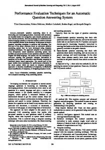
Fig. 2. Graph search from node ng to ns
ated graph planning approach described in [2]. As in many planning algorithms, this algorithm incorporates a graph search algorithm that strives to find the lowest cost path through a graph that is composed of nodes (representing system states) connected by edges (representing system actions). The cost of a path through the graph is defined as the sum of the action costs (the edges) plus the costs of having occupied the traversed states (the nodes). One such graph search algorithm is Dijkstra’s shortest path algorithm [3]. An example of this algorithm is shown in Figure 2 and may be summarized as follows: 1. Initialize the search. This includes setting the initial cost of all nodes (in the figure nodes are shown as circles and node costs are the bold numbers next to them) to infinity, and creating an set of open nodes that only contains the goal node (ng ) at a cost of zero. An open node is a node that the search has reached but not evaluated. Nodes that have been fully evaluated are shown as bold circles in the figure. 2. Find the least expensive member of the open set (denote this node by ncheap ) and remove it from the open set. 3. Compare ncheap to the start node (ns ). This search proceeds from the goal to the start, so if ncheap is equal to the start node the search is finished. It can be noted that this search may also proceed from start to goal without loss of generality. 4. Expand ncheap . During this step, the cost of reach-
ing each of ncheap ’s predecessors (nodes connected by lines in the figure) must be determined. The following steps occur for each predecessor: (a) Determine the cost of the edge that connects ncheap to the predecessor and the cost of occupying the predecessor. (b) If the sum of these two costs plus the cost of ncheap is less then the current cost of the predecessor, the edge is maintained as a forward pointing edge (set to bold in the figure), any previous forward pointing edge is removed, and the predecessor is added to the open set. 5. Go to step 2. An example of this algorithm’s application is shown in Figure 2. The optimal path from any expanded node to ng lies along the decreasing cost path of bold edges (follow the arrows). For this example, the search proceeds from the node labeled ng to the node labeled ns . The search terminates at the optimal answer when the node ns is examined for expansion. The optimal path found may be seen to be ns − n5 − n4 − n2 − ng . As seen from the above algorithm description, each loop of the algorithm must make multiple calls to a cost generating function (step 4a). A single plan may entail several hundred or even thousands of algorithm loops, and the cost generator is at the heart of the loop, making its performance critical. It is this fact that leads to the requirement for a C++/C/Java API rather then a central server with socket calls. The overhead of such a server would be prohibitively large for this application. The actual interface to the planning system is quite simple. As the planner expands nodes, it passes the current node (and its associated state information) and the predecessor node (along with its associated state information) to the cost generator. The cost generator then returns the incremental cost of the transition plus the cost of occupying the predecessor node.
III. Coarse Evaluation Procedure and Results The first step in the analysis was to identify existing tools and languages that appeared to satisfy our highlevel requirements, which are: • C or C++ interface: Because of the heterogeneous nature of the systems that will utilize the cost generator, integration was an integral part of the analysis. A well-defined application programming interface (API) to incorporate the cost function into existing code was of utmost importance. The majority of the code used in the planner and the moving object prediction software is written in C/C++, giving languages with C interfaces a distinct advantage for our application.
Cost: Since the 4D/RCS architecture, and its components, should not be cost prohibitive to disseminate and use, the tool must be free or have an extremely low cost. • Ease of Use, Understandability, and Maintainability: It is important that a person who is using the tool be able to easily encode and modify the rules pertaining to the cost model, and be able to easily see which rules are firing during a given situation. Rule-based and functional approaches lends themselves better to representing rules explicitly, unlike imperative approaches which tend to hide much of the rules in code III-A. As such, our analysis focused on rule-based and functional approaches. • Real-time execution: 4D/RCS, as described in I, is developed for, and has been applied to, domains for real-time planning and control. As such, any tool that interfaces with or is built into the architecture must also lend itself to real-time execution. Though we would have preferred tools with hard real-time performance, our preliminary research showed that very few of these tools exists. As such, we allowed for tools that claimed soft real-time performance. • Support: For this effort, it is important that the tool chosen has a strong support community to allow us to more easily tackle implementation challenges as they arise. •
Through web searches and literature review, eight tools were identified that showed promise in being able to represent cost models within the 4D/RCS framework. This listing is not meant to encompass every tool that is available; it is simply meant to provide a sampling of the types of tools that have the potential to satisfy the aforementioned requirements. The tools that were identified are: Tool A - Tool A is a C-based development and delivery expert system tool that provides an environment for the construction of rule and/or object-based expert systems. Tool A’s knowledge representation can handle rule-based, object-oriented, and procedural knowledge. It can be embedded within procedural code, called as a subroutine, and integrated with languages such as C, Java, FORTRAN and ADA. • Tool B - Tool B is an object-oriented environment for building and deploying real-time expert system applications. Tool B is primarily targeted for companies that are trying to improve their efficiency. It allows the company a mechanism to reason over information within their databases in order to monitor potential problems, diagnose root causes, and recommend corrective actions. • Tool C - Tool C is a general purpose, purely functional programming language. In particular, it is a polymorphically typed, lazy, purely functional language. It is based on Lamda Calculus and its primary
•
purpose is to help write and maintain large software systems. It is especially tailored for writing specifications which can themselves be executed. • Tool D - Tool D is a rule engine and scripting environment written entirely in the Java language. Tool D was originally inspired by the Tool A expert system shell, but has grown into a complete, distinct, dynamic environment of its own. Tool D allows one to build Java software that has the capacity to ”reason” using knowledge supplied in the form of declarative rules. • Tool E - Tool E is a logic/functional programming language, designed and implemented by a small group of researchers at the University of Melbourne, Australia. It is based on a purely declarative programming paradigm, and was designed to be useful for the development of large and robust ”real-world” applications. It provides the traditional logic programming syntax, but also allows for user-defined functions, integrating logic and functional programming into a single paradigm. Tool E addresses the problems of large-scale program development, allowing modularity, separate compilation, and numerous optimization/time tradeoffs. • Tool F - The Tool F Programming System is a development platform for intelligent, distributed applications. Tool F is based on the Oz language, which supports declarative programming, object-oriented programming, constraint programming, and concurrency as part of a coherent whole. Oz is a constraint language with logic variables, finite domains, finite sets, rational trees and record constraints. Tools and libraries are provided built on the concepts of first-class computation spaces and determinacy-driven disjunctions. • Tool G - Tool G is a code-generating C++ class library that encapsulates the Eclipse inference engine. Tool G can be embedded within C++ applications so that rules can operate directly on C++ objects and monitor them as C++ code constructs, modifies, and destroys them. Tool G uses the Rete Algorithm. The Rete Algorithm is widely recognized as by far the most efficient algorithm for the implementation of production systems. The algorithm was originally developed by Charles Forgy in the course of obtaining his PhD from Carnegie Mellon University in 1979. Rete is the only algorithm for production systems whose efficiency is asymptotically independent of the number of rules. • Tool H - Tool H is a general cognitive architecture for developing systems that exhibit intelligent behavior. Tool H attempts to: 1) work on the full range of tasks expected of an intelligent agent, from highly routine to extremely difficult, open-ended problems, 2) represent and use appropriate forms of knowledge, such as procedural, declarative, episodic, and possibly iconic, 3) employ the full range of problem solving methods, 4) interact with the outside world and learn
about all aspects of the tasks and its performance on them. The above eight tools were held up to the five requirements described previously. Table III of the Appendix shows the results. The following are the observations from Table III: • Due to Tool B and Tool G’s cost, we eliminated them from further consideration. • Due to the lack of support and the benefits of a rulebased language discussed further in III-A, Tool F and Tool C were eliminated from further consideration. • Due to the lack of activity on the mailing lists (only five messages in the last month - August - and none in the last five days - 8/15/03 - 8/20/03 ), the uncertainty behind who was using Tool E and how it was being used, and the fact that the web page did not appear to have been updated since 2002, Tool E was eliminated from further consideration. This left Tool A, Tool D, and Tool H as the three tools that were to be further analyzed. A. Why Rule-Based? In our initial examination of the tools, it became clear that the rule-based approaches were the most natural for this application. The rule-based systems offered 2 distinct advantages over a functional or procedural language. Because the ultimate goal is to represent a real world situation that is governed by explicit rules, a rule-based system provides an intuitive means for capturing the logical constraints [5]. Consider the following trivial example in a rule-based language versus its imperative counterpart: (A) (defrule warning-if-low-tank (tank (name ?name) (low TRUE) (intact TRUE)) (not (warning low ?name)) => (assert (warning low ?name)) (printout t "WARNING: TANK " ?name " IS LOW!" crlf) ) (B) void warn_if_low( ){ for(int i = 0; i < num_tanks; i++){ for(int j = 0; j < num_warnings; j++){ if(((tank[i].low == TRUE && tank[i].intact == TRUE)) && ((warning[j].status != low) && (warning[j].name != tank[i].name))){ warning.add(Warning( low, tank[i].name)); printf(‘‘WARNING: TANK IS LOW’’); } } }
These functions check to see if there is a tank that is both intact and low, and if so, if there is not already a warning on record that the tank with the name matched from the initial clause is dangerously low. If both of these these conditions evaluated to true, a warning is added that the given tank is low and a message is displayed to alert the user. While this is a contrived example which may be expressed more eloquently in another imperative language, the underlying principles are the same as they would be in a full-scale program. In (A), we see how the pattern matching capabilities of most rule-based systems offer a more succinct alternative to traditional control structures. The high level description allows for more understandable rules. The system is responsible for implementing all of the nested if/else, and looping syntax, leaving much more readable and maintainable code for the programmer. It also illustrates the proclivity of rule-based systems for representing real-world constraints. If certain conditions are fulfilled, then take the specified action. In our application, if certain rules of the road are violated, then some cost is assigned to that action, making it a less desirable node to expand on the planning graph.
IV. Fine Evaluation Procedure The rules governing on-road driving are extensive. For this phase of the project, we selected a small subset of these rules to implement in each of the three environments that were chosen from Section III. These rules vary in terms of their complexity and inference requirements, but together they represent a distributed sampling from the broad spectrum of situations a vehicle may encounter. The purpose of this phase of the project was not to encode all of the rules of the road into every available system, but rather to see how each of the proposed systems performed given a subset of the specific requirements for this project. A. The Rules With this in mind, five simple driving situations were modeled in each of the systems. The most trivial of these is speed-limit-violation. This rule checks the vehicle’s speed against the posted speed limit in the knowledge base, and asserts a cost if the vehicle is traveling above or below a given threshold of the speedlimit. The cost generated is linear with respect to the difference between the vehicle’s actual speed (Va ) and the posted speed limit (Vp ): cost = K|Va − Vp |
(1)
The second rule governs lane changes and addresses the situation of a vehicle traveling in some lane, LS1, and considering moving to some other lane LS2. As
described earlier, the planner will utilize the cost function to accrue costs for each node in a given path. Whichever path is the least costly is the one that will be selected. By assigning a small cost to moving from LS1 to LS2, it deters the planner from changing lanes in an erratic manner unless there is some other cost (like that of a collision) which is greater. Therefore, any lane segment transition will produce a small cost, while transitions which break laws, such as crossing a solid line or passing in a marked no-passing-zone, incur greater costs. The third rule deals with a vehicle approaching a stop sign. If the vehicle is positioned at a stop sign, has a velocity that is greater than zero, and had a velocity at the previous time-step that was also greater than zero, then the vehicle never came to a stop. This will cause the vehicle to incur a cost for running a stop sign. In the current implementation, this rule will only be activated if the vehicle is positioned on the road exactly parallel to the location of the stop sign. Future versions of the rule will be modified so that it is activated within a given sphere of influence of the stop sign such that nodes within that sphere with higher velocities will have greater costs associated with them. This will encourage the planner to decelerate slowly as the vehicle approaches the stop sign. The fourth rule deals with an intersection of two, two-lane roads, that do not contain any other vehicles or moving objects. It dictates the legal lane traversals that a vehicle approaching an intersection can take given its current lane. Because it is the junction of two, two-lane roads, there are seven possible traversals that the vehicle can make as shown in Figure 3. The illegal transitions will place the vehicle on the wrong side of the road, and therefore incur a significant cost. Legal traversals that cause the vehicle to cross oncoming traffic (i.e. legal left-hand-turn, legal-straight) will incur a nominal cost for the increased risk associated with this behavior. The cost is small enough so that it is offset by the cost of traveling further from the desired destination so that the planner is not discouraged from making these legal maneuvers. The final rule also deals with the traversal of an intersection of two, two-lane roads; however in this instance there are other vehicles on the road. The actual and predicted positions of these vehicles are available from the moving object prediction software for ten time-steps into the future along with the prediction uncertainty at each step. Our vehicle’s position in this case relates to a projected position of our vehicle with respect to a plan that the planner is evaluating. Therefore, this transaction occurs through the use of a query: the planner provides the tuple (time,location,velocity) of our projected position at a given time, and the rule base responds with a cost based on the probability of
V. Fine Evaluation Results In this section, we will examine the three tools chosen from section III, and discuss how they performed within the procedure discussed in section IV. The two main metrics that we will discuss are usability and trial benchmarks. A. Usability
Fig. 3. Intersection of two, two-lane roads with the available lane transitions marked
another vehicle occupying that locale based on the predictions from the moving object recognition module. B. Simulated Environment Framework In order to accurately assess the capabilities of the tools for the specific needs of the project, it was necessary to see how they performed within the rubric of a dynamic world model. Because of the preliminary nature of this phase of the research, integration with the existing world model was not practical. Instead, an environment framework was developed to simulate the flow of data from the world model. This allowed us to assess the capabilities of the various packages under dynamic conditions. The simulated environment framework consists of two parts: the knowledge modules and the driver. The knowledge modules represent a snapshot of the data that would be available from the world model at some time, Tn . They contain information about our vehicle, other vehicles of interest, signage, lane-markings, intentions, and intersections. These modules are generated dynamically from a set of possible values and allow us to run the systems with any number of iterations to see how increased change in knowledge affects performance. The software driver is responsible for linking the knowledge modules with the knowledge base of the system. Each iteration, new knowledge is asserted to the knowledge base as it becomes available, and older knowledge is retracted as it loses relevancy. This simulates the changing world model that is typical of a real-world environment.
Usability can be seen as a subjective metric, so this discussion will be limited to specific facts about the tools and how they were able to be used for the purpose of cost-generation. Sebesta [4] describes readability as “one of the most important criteria for judging a programming language” (p.8). It is a measure of the ease with which programs in a given language can be read and understood. This evaluation is domain sensitive, in that a language may be able to describe some situation very eloquently, while another application in the same language within a different domain could be convoluted. Because Tool D was orignally inspired by Tool A, the grammar and syntax are nearly identical, and most valid Tool D code is still compatible with a Tool A environment, and vice versa as stated in Tool D’s documentation. Therefore, the usability evaluation criteria are nearly identical for the two, with the exception of support. Both Tool A and Tool D were exceptional in their readability in the domain of rule oriented cost generation. The syntax is simple and intuitive, with a small number of basic components. Tool H was slightly less readable, and required more expertise to accomplish similar tasks to those done in Tool D/Tool A. The syntax is largely oriented in triples - entity, attribute, value - and can be confusing to read. Expressivity is the conveniences a language provides for accomplishing certain tasks [4]. In section III-A this was addressed for the scope of all rule-based systems, and those general comments apply to all three of the systems chosen. More specifically, Tool H provided the unique ability to separate the proposal of an action from the execution of the action. Based upon a private conversation with a developer of this tool, the division allows for increased flexibility and more robust conflict resolution. Conversely, Tool D/Tool A provided only minimal support for user-defined conflict resolution, and recommended in the documentation that this be left up to the system. Support also plays a significant role in the usability of a system. The inevitability of errors and questions necessitates an active user community to assist the developer in resolving the problem in a timely fashion. Tool D has a relatively small, yet extremely active user community. The Tool D mailing list provides a forum for discussing problems and questions and is moderated by Ernest Friedman-Hill, the author of Tool D,
who usually replies within hours of a post. In addition, the on-line references provide extremely helpful guidance for the novice and advanced programmer alike. Tool H has also been well documented and is being applied to a variety of different domains by a large number of academic and research institutions. In addition, a small company was formed for the purpose of extending Tool H and applying it to technical domains. In doing this research, we had several interactions with this company to overcome technical hurdles. Tool A documentation is also extensive and provides support for the basic and more advanced features of the language. There is a thread-based discussion group available from the Tool A website, as well as a mailing list for Tool A users.
TABLE I Tool D Results
Dataset 1 2 3
10 .88s .89s .88s
Number of Iterations 100 500 1000 3.01s 10.75s 17.41s 3.03s 10.73s 17.28s 3.02s 10.70s 17.24s
TABLE II Tool A Results
Dataset 1 2 3
Number of Iterations 10 100 500 1000 .05s .51s 2.68s 5.12s .05s .51s 2.67s 5.12s .05s .51s 2.70s 5.12s
B. Trial Benchmarks Utilizing the rules from section IV-A and the framework from section IV-B, we ran trials on the systems to see how they performed under conditions similar to those specific to our domain. The benchmarks were done to roughly gauge the performance of the systems. They are not intended to reflect the overall performance of the systems. The timing trials were included in the analysis as general observations about unoptimized code under specific conditions. Only tables for Tool A and Tool D are included below. Tool H is a fundamentally different type of rulebased system, both in the way it encodes the rules as well as the way it decides which rules to fire. Due to these differences, there was no meaningful correlation between the numbers shown in the Tool A and Tool D tables and those for Tool H. Instead, the most meaningful metric for Tool H is the time it takes to go through one decision cycle. Using a subset of the rules described in IV-A and without the framework from IV-B, we ran Tool H through five decision cycles, at an average speed of 87.5 milliseconds per decision cycle. However, this does not involve the expensive input/output operations charged to both Tool A and Tool D in their respective frameworks. It should be noted that Tool H includes a fair amount of overhead for functionality that we are not actively using in this framework. In many ways, we are grossly under-utilizing Tool H’s capabilities for this effort. Therefore, the remainder of this analysis will focus primarily on Tool D and Tool A. The number of iterations refers to the number of knowledge modules from section IV-B. We ran trials with 10, 100, 500, and 1000 iterations to observe how the systems performed as the knowledge bases increased. Three unique datasets were generated for each of the three sets of iterations to ensure that the times were consistent. Timing was done using the Unix command time, and trials with CPU usage under eighty-
five percent were discarded. The times shown in Table I and Table II are an average time done over five trials. In all three stages Tool A outperformed Tool D. At 100 iterations, Tool A was approximately 6 times faster than Tool D, while at 1000 iterations it drops to less then 3.5 times faster. Future work could examine if the two systems converged in speed for a sufficiently large data set. C. Analysis While Tool D and Tool H were both able to accomplish the simulated task, Tool A emerged as the most natural selection for the cost-generator for onroad driving. The reasons for this are twofold: Tool A was designed to be embedded within other programs, specifically within C programs as stated in the documentation. While it would be possible to interface both Tool D and Tool H with existing C code using native function calls in Java and TCL, Tool A provides functionality specifically for integration with C programs. Second, within the specific conditions incidental to our domain, Tool A was able to perform faster than its counterparts (Table II). Because of the real-time requirements described in Section III, the speed with which Tool A was able to complete hundreds and thousands of iterations should allow it to be used within the planning and moving object prediction systems within the 4D/RCS framework. While Tool H has a powerful inference engine, the overhead associated with that power wasprohibitive for our application. The additional features that we would gain from using Tool H were interesting from a theoretical standpoint, but were not essential for our application.
VI. Conclusions and Future Work The cost-generating sub-system within the autonomous vehicle framework will play an essential role
in a number of other systems in the vehicle, including path planning and moving object prediction. An adequate means for representing the constraints that generate these costs, as well as managing and relaying these costs to other systems is necessary. In order to accomplish this, we had to first determine a suitable tool for developing the cost-generator. Based on domain specific criteria, we were able to narrow the the selection to three potential tools. Preliminary testing of these tools suggested that Tool A showed the most promise for the aforementioned tasks. Future work will further examine Tool A ability to adapt to dynamic, and increasingly larger data sets. We will perform more extensive testing in order to fully understand the timing results. Furthermore, the rule base will continue to be expanded and refined to allow the vehicle to react to a wider variety of more complex situations in an intellgient fashion.
References [1] J. Albus and et.al. 4D/RCS Version 2.0: A Reference Model Architecture for Unmanned Vehicle Systems”. Technical Report NISTIR 6910, National Institute of Standards and Technology, Gaitherburg, MD 20899, U.S.A., 2002. [2] Stephen B. Balakirsky. A Framework for Planning with Incrementally Created Graphs in Attributed Problem Spaces. Akademische Verlagsgesellschaft Aka GmbH, 2003. [3] Dijkstra EW. A Note on Two Problems in Connexion with Graphs. Merische Mathematik, pages 269–271, 1959. [4] Robert W. Sebesta. Concepts of Programming Languages. Addison Wesley, 2002. [5] David A. Watt. Programming Language Concepts and Paradigms. Prentice Hall, 1990.
Appendix TABLE III Coarse Evaluation
Language
Paradigm
APIs
Real-time Execution
Cost
Support
Tool A
Rule-based
C/C++
Based on Rete Algorithm
Public domain
Tool B
Rule-based Functional
Concurrent realtime execution Functional languages typically slow (Watts)
6000 - 37000
Tool C
Could not be determined Tools available for interface with C and Java
Tool D
Rule-based
Java
Based on Rete Algorithm
Academic and research use free, licensed for commercial use
Tool E
Rule-based
C Interface
Unable to determine
Public domain
Tool F
Flavors of functional and rulebased
Tcl/Tk
Functional languages typically slow (Watts)
Public domain
Tool G
Rule-based
C++, Java
7500 per CPU
Tool H
Rule-based
Java, SGIO interface with C
Based on Rete Algorithm At best a soft real-time system
Large community, mailing lists, previously applied to robotics applications Paid customer support Little support for robotic apps, mostly used by educational institutions Small but active community, mailing lists, on-line documentation Mailing lists with little activity, unclear how many people are using it Little support for robotic applications, not widely used Paid customer support Large community, mailing lists, previously applied to robotics apps
Public domain
Public domain