Proceedings of the 2007 IEEE Symposium on Foundations of Computational Intelligence (FOCI 2007)
Performance of a Simple Tuned Fuzzy Controller and a PID Controller on a DC Motor Oscar Montiel1, Roberto Sepúlveda1, Patricia Melin2, Oscar Castillo2, Miguel Ángel Porta1, Iliana Marlen Meza1 1
Centro de Investigación y Desarrollo de Tecnología Digital del Instituto Politécnico Nacional (CITEDI-IPN) Av. del Parque No. 1310, Mesa de Otay, Tijuana, B. C., México.
[email protected]. 2
Department of Computer Science, Tijuana Institute of Technology P.O. Box 4207, Chula Vista CA 91909, USA.
[email protected] explain and implement them [9]. The main problem of using PID controllers is the effect acquired as a result of disturbances and environmental conditions on the structure of the system [10], adding complexity to the controller’s design. However it is not easy to find another controller with such a simple structure to be comparable in performance. A very important step in the use of controllers is the tuning process. In a PID controller, each mode (proportional, integral and derivative mode) has a gain to be tuned, giving as a result three variables involved in the tuning process. On the other hand, the tuning of a fuzzy controller is a heuristic work, sometimes becomes overwhelming to find the optimal parameters necessaries for a well performance of the controller; then, the use of these at industry is not so popular. Applying the STA, it is possible to facilitate the tuning process, since STA only needs the tuning factor k to do it [11]. This paper is focused on the experimental results of the simple tuned fuzzy controller of Pulse Width Modulation (PWM) applied to regulate the revolutions per minute (rpm) of a DC motor [1], see Figure 1. Then a comparison with the PID controller’s performance is made. This work is organized as follows. Section 2 introduces the description of the fuzzy model employed, with its membership functions and rules. Section 3 describes the methodology of the STA used to manipulate the settling time of the system. Section 4 describes the PID controller and its tuning process. In Section 5, the obtained results of the physical experimentation with both controllers are presented. Finally, in Section 6 we have the conclusion.
Abstract — We are presenting the usefulness of an innovative method called Simple Tuning Algorithm (STA) for tuning fuzzy controllers, it has only one variable to adjust to achieve the tuning goal, this in counterpart to other methods like the Proportional Integral Derivative (PID) controller wish has three variables to adjust for the same goal. Comparative examples of the STA and the PID methods are presented in a speed control of a real DC gear motor application. The PID controller was tuned using the Ziegler-Nichols. In base of the obtained quantitative and qualitative measures and observations, we are concluding that the fuzzy controller performance outperformed the PID controller; moreover, the tuning process using the STA method was easier than using the Ziegler-Nichols method. Keywords: Fuzzy Logic, Simple Tuning Algorithm, DC motor, PID.
1. Introduction Nowadays, the quest for new controllers which provide functionality and guarantee a precise performance has led the technology into the field of Fuzzy Logic. New ways to control systems have been developed based mostly in this area of knowledge, some examples are control of DC motors [1][2], security systems [3], antilock braking systems (ABS) [4], speech enhancement [5], path planning [6][7], among others. Despite this, practical applications involving fuzzy controllers as a proved option to conventional controllers are hard to find. One of the most popular controllers used in industrial processes is the Proportional Integral Derivative (PID) controller [8]. The real strength of this kind of controller is its simplicity to understand,
1-4244-0703-6/07/$20.00 ©2007 IEEE
531
Proceedings of the 2007 IEEE Symposium on Foundations of Computational Intelligence (FOCI 2007)
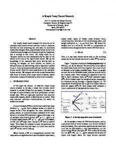
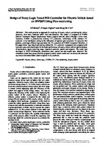
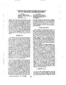
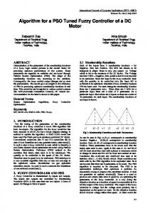
2. Fuzzy Model Description The fuzzy controller consists of 25 rules based on five fuzzy regions. This design considers the speed error and the change of the error as the input sets. The output is the duty cycle of the PWM signal sent to the power stage so the desired no-load speed is reached. Table I shows the controller fuzzy variables employed. Figures 1, 2, 3 and 4 show the membership functions of the error input variable, the change of error input variable, the duty cycle output variable and the control surface of the fuzzy controller, respectively, under their initial conditions before applying the STA. The fuzzy associative memory, integrated by 25 rules, is shown in Table II.
Figure 2. Membership functions of the change of error input variable.
TABLE I FUZZY CONTROLLER’S VARIABLES.
Input variables Error
NB: Negative Big N: Negative Z: Zero P: Positive PB: Positive Big
Error change NB: Negative Big N: Negative Z: Zero P: Positive PB: Positive Big
Output variable Control Action (Duty Cycle) BD: Big Decrease D: Decrease H: Hold I: Increase BI: Big Increase Figure 3. Membership functions of the duty cycle output variable
3. Simple Tuning Algorithm (STA) for a Fuzzy Controller. In the implementation of a fuzzy controller is necessary to consider many parameters to compute, like, number and ranges of membership functions, rules, shapes, percentages of overlap, etc. [12]. The algorithm implemented in this system was proposed by Eduardo Gómez Ramírez in [11]. It is based on the properties of the control surface, allowing the modification of the controller’s behavior by means of manipulating the ranges of the membership functions of the input variables, and it only implies a single variable (instead of a PID controller, which needs to find at least three parameters for tuning). The membership functions of the output fuzzy variable remain constant.
Figure 1. Membership functions of the error input variable.
532
Proceedings of the 2007 IEEE Symposium on Foundations of Computational Intelligence (FOCI 2007)
Where Vop initial are the normalized values of the
membership functions in the x-axis and r (k ) is the polynomial:
r (k ) = 4.
Figure 4. Control surface of the fuzzy controller.
30k 3 + 37 k 2 + 52k + 1 40
(2)
Renormalization of the ranges of the fuzzy variables. Convert the normalized range to the previous range of the system. This can be computed only multiplying the Vop vector by a constant factor.
4. PID Controller In the industry, PID controllers are the most common control methodology to use in real applications. Fundamentally, it is composed of three basic control actions (see Table III). They are simple to implement and they provide good performance. The tuning process of the gains of PID controllers can be complex because is iterative: first, it is necessary to tune the "Proportional" mode, then the "Integral", and then add the "Derivative" mode to stabilize the overshoot, then add more "Proportional", and so on.
TABLE II FUZZY ASSOCIATIVE MEMORY FOR THE CONTROL SYSTEM.
ce
e NB N Z P PB
NB
N
Z
P
PB
BI BI BI BI BI
BI I I H I
I H H H D
D H D D BD
BD BD BD BD BD
Experiments were made with the STA in an application of controlling the no-load speed of a real DC gear motor. The goal of the experiments was to manipulate the settling time of the system. The method consists basically in four steps: 1.
2.
3.
TABLE III BASIC CONTROL ACTIONS.
[ ]
Tuning Factor Selection. A number k ∈ 0,1 is used to define the tuning adjustment level. k = 0 is the biggest settling time and k = 1 the smallest. Normalization of the ranges of the Fuzzy Controller’s variables. The range of each input fuzzy variable is modified in order to have the lower and upper limits equal to -1 and +1, respectively. Tuning Factor Processing. Once the range is normalized, the new vector of operation points will be given by:
Vop final = (Vopinitial )
r (k )
Proportional Control
u (t ) = K p e(t )
Integral Control
u (t ) = K i ∫ e(t )dt t
Derivative Control
0
u (t ) = K d
d e(t ) dt
a) Controller description The PID controller has the following form in the time domain [8]
de(t ) 1 u (t ) = K p e(t ) + Td + dt Ti
(1)
where
e(t )
t
0
(3)
is the system error (difference between the
reference input and the system output),
533
∫ e(τ )dτ u (t )
the control
Proceedings of the 2007 IEEE Symposium on Foundations of Computational Intelligence (FOCI 2007)
variable,
Kp
the proportional gain,
time constant and
Ti
Td
certainly process dependent. A number of methods have been proposed in the literature over the last 50 years [13]. Then tuning a PID algorithm, generally the aim is to match some preconceived 'ideal' response profile for the closed loop system. Many algorithms have been developed to guarantee the best performance of the PID controller. We used the Ziegler-Nichols method to optimize the parameters of the proportional (P), integral (I), and derivative (D) modes of the PID controller. The Ziegler-Nichols method tunes the gains of the PID law of control. This algorithm can be described by the following steps:
the derivative
the integral time constant. Equation
(3) can also be written as
u (t ) = K p e(t ) + K d
where
K d = K p Td
t de(t ) + K i ∫ e(τ )dτ (4) 0 dt
and
K i = K p Ti
.
Each
coefficient of the PID controller adds some special characteristics to the output response of the system. Because of this, choosing the right parameters becomes a crucial decision for putting into practice this controller. The effects of these parameters on the output response of the system are shown in Table IV.
• •
•
value. Make a small setpoint change and observe the response of the controlled variable. Increase K p by a factor of two and make another
•
small change in the setpoint. Keep increasing K p (by a factor of two) until the
• b) Control objective A PID controller does not "know" the correct output to bring the system to the setpoint. It moves the output in the direction which should move the process toward the setpoint and needs to have feedback (measurements) to perform.
• •
TABLE IV EFFECTS OF THE GAINS IN THE RESPONSE OF THE SYSTEM.
Gain
Raise time Dec
Overshoot
Kd Ki
Kp
Inc
Settling time —
Steady-State error Dec
Inc
Dec
Dec
—
Dec
Inc
Inc
Zero
the period of the oscillations. When the load and the noise in the system is zero, K p should be a high value in order to ensure that the process output is close to the desired setpoint. If exists noise in the system, K p should be moderate or the system will be too
The objective of the PID controller is to ensure that the DC motor reaches a desired velocity. For this, a velocity-error, denoted by e(t ) ∈ ℜ , is defined as
sensitive to noise. Obviously the setting of K p is a balance between stability, noise sensitivity and load regulation [14].
(5)
TABLE V ZIEGLER-NICHOLS PARAMETERS ADJUSTMENTS.
where vd (t ) ∈ ℜ denotes the desired velocity for the
Control Action
DC motor. c)
response becomes oscillatory. Find the period between oscillations. Apply the criteria of Table V for the other parameters of the controller.
The control law settings are then obtained adjusting the controller’s parameters according to Table V, considering Ku as the final value of K p and Pu as
Inc = Increases — Dec=Decreases
e(t ) = v(t ) − v d (t )
Set the controller to P mode only. Set the gain of the controller ( K p ) to a small
P
PID Tuning Process — The Ziegler-Nichols of closed loop method
Controller tuning involves the selection of the best values of the gains of K p , K i and K d of the PID control law. This is often a subjective procedure and is
534
Kp Ku
PI
Ku
PID
Ku
Ki
Kd
2
2.2 1.7
Pu Pu
1.2 2
Pu
8
Proceedings of the 2007 IEEE Symposium on Foundations of Computational Intelligence (FOCI 2007)
5. Experiments and Results a) Application description In order to measure the behavior of the controller’s output over the DC motor application, the model of both controllers was designed in Simulink® of Matlab® (see Figures 5 and 6).
Figure 7. Membership functions of the error with k = 0.91.
Figure 5. Simulink® system model for the fuzzy controller.
Figure 6. Simulink® system model for the PID controller.
Figure 8. Membership functions for change of error with k = 0.91.
The intention is to find an optimal tuning factor k considering these premises: 1. The system needs sensitivity to disturbances and the smallest settling time. This happens at the nearest k values to 1.
b) Optimal tuning factor k test for the fuzzy controller using the STA
2. The optimal k is the one that makes the fuzzy controller to reach the no-load speed target in the minimum time with a smooth curve.
Following the STA [11], the first step is the selection of the tuning factor k, which defines the slope adjustment for the membership functions. For the DC motor it is necessary a value near to k = 1, since the smallest settling time is desired. Therefore, previous to comparison with the PID controller, several runs were made for different values of k, taking the DC motor’s no-load speed from 0 to 32 rpm.
3. The controller reaches the target till the fuzzy controller input change of error is minor than δ = 0.001. Under these premises, the simulation ran for k = 0.5 to k = 1 with steps of 0.01, rejecting values of k < 0.5 because of premise 1. The experiments results show that the optimal value of k is k = 0.91. The settling time for k = 0.91 it is around 200 ms, and the system response presents a smooth curve. The effect in the membership functions of each input value and the control surface are shown in Figures 7, 8, 9, respectively.
535
Proceedings of the 2007 IEEE Symposium on Foundations of Computational Intelligence (FOCI 2007)
Figure 9. Control surface for the fuzzy controller for k = 0.91.
Figure 12. An ISE comparison for both controllers, note the graph shows only till 400 ms for a better appreciation of the differences of each ISE values.
c)
PID controller tuning results
For the PID, several experiments were made in order to tune the optimal values of K p , K i and K d of the controller. The experimental values for Ku and Pu respectively were 0.374 and 1.84. Applying the Ziegler-Nichols criteria of Table V, the optimized tuned values of K p , K i and K d of the PID controller are shown in Table VI. TABLE VI ZIEGLER-NICHOLS PARAMETERS ADJUSTMENTS OF THE PID CONTROLLER FOR THE EXPERIMENTS.
Figure 10. System response with the Simple Tuned Fuzzy controller.
Control Action Kp Ki P 0.187 PI 0.170 1.533 PID 0.22 0.920
Kd 0.230
d) Comparison of results As mentioned before, the optimal tuning factor is k = 0.91, according to physical experimentation. The system response of the fuzzy controller is shown in Figure 10. For the PID, the target is reached also around 200 ms. The system response is shown in Figure 11. In order to compare the results about the performance of both controllers in discussion, an Integral Square Error (ISE) performance criteria is applied to the experimental results obtained. For the PID controller, the ISE is 15834, and for the fuzzy controller is 9818. Figure 12 shows the ISE graph of each controller.
Figure 11. System response with the PID controller.
536
Proceedings of the 2007 IEEE Symposium on Foundations of Computational Intelligence (FOCI 2007) [8]
6. Conclusions The tuning process of the fuzzy controller applying the STA falls into making a decision about the tuning factor k. The adequate selection of the k value is necessary to obtain the desired settling time for the system. The tuning of the PID controller implies an iterative method of finding the appropriated value for the proportional gain of a reduced model in P mode, when this gain of the simplified model of the PID controller has been found, it is necessary to change to a PD mode, and then compute the integral gain. The process should be repeated until the full tuning of the PID controller has been achieved. In the development of this application was easier to tune the fuzzy controller using the STA compared with the tuning of the PID controller because the STA needs only to adjust one parameter. Contrary to this, the PID controller needs an entire iterative process to find the better constant values for the proportional, integral and derivative mode to provide a good performance. According the results, it is remarkable that the use of fuzzy controllers tuned with the STA can be considered as a viable and efficient technology to substitute PID controllers in real control applications.
[9]
[10]
[11] [12] [13]
[14]
REFERENCES [1]
[2]
[3]
[4]
[5]
[6]
[7]
Porta García M, Meza Sanchez, I., Montiel O., Sepúlveda R., Castillo O, “Simple Tuning of a Fuzzy Pulse Width Modulation Controller for a DC Motor Applicacion,” in Proc. of The 2006 International Conference on Artificial Intelligence ICAI’06, 2006, pp. 558-564. Niasar A. H., Vahedi A., Moghbelli H., “Speed Control of a Brushless DC Motor Drive via Adaptive Neuro-Fuzzy Controller Based on Emotional Learning Algorithm,” in Internacional Conference on Electrical Machines and Systems ICEMS 2005, 2005. Huang Y., Cheng P., “Using Fuzzy Inference Method to Automatically Detect and Identify Intruders from the Security System,” in IEEE International Conference on Networking, Sensing & Control, 2004. Mirzaei, A.; Moallem, M.; Mirzaeian, B.; Fahimi, B., “Design of an optimal fuzzy controller for antilock braking systems,” in Vehicle Power and Propulsion, 2005 IEEE Conference Volume I, Issue , 7-9, 2005 pp. 823 – 828 Thevaril J., Kwan H. K., “Speech Enhancement using Adaptive Neuro-Fuzzy Filtering,” in Proc. of 2005 International Symposium on Intelligent Signal Processing and Communication Systems, ISPACS 2005, 2005. Wang M., Liu J., “Fuzzy Logic based robot path planning in unknown environment,” in Proc. of the Fourth International Conference on Machine Learning and Cybernetics ICMLC, 2005, pp. 18-21. Zhang N., Beetner A., Wunsch D., Hemmelman B., Hasan A., “An Embedded Real-Time Neuro-Fuzzy Controller for Mobile Robot Navigation,” in Proc. The 2005 IEEE International Conference on Fuzzy Systems, 2005.
537
Visioli A., "Tuning of PID controllers with fuzzy logic,” in IEE Proceedings - Control Theory and Applications, 2001, Volume 148, Issue 1, pp. 1-8 Zhang J., “Structural research of fuzzy PID controllers,” in Proc. International Conference on Control and Automation, ICCA2005, Northeastern University, Qinhuangdao Hebei China. 2005. Visioli A., “Fuzzy Logic Based Set-Point Weight Tuning of PID Controllers,” IEEE Transaccions on systems, man and cybernetics – Part A: Systems and Humans, Vol. 29, No. 6, 1999. Gómez Ramírez E., “Simple Tuning of Fuzzy Controllers,” in International Conference on Fuzzy Systems, Neural Networks and Genetic Algorithms, FNG 2005, Tijuana, Mexico, 2005. R. Sepúlveda, O. Montiel, O. Castillo, and P. Melin, Fundamentos de Lógica Difusa, México: ILCSA, 2002. Willis M. J., “Proportional-Integral-Derivative Control,” Dept. of Chemical and Process Engineering University of Newcastle, 1999. [online] available at: http://lorien.ncl.ac.uk/ming/pid/PID.pdf Jantzen J., Tuning of fuzzy PID controllers, Tech. report no 98H 870, Technical university of Denmark, Dept. of Automation, Sept. 1998. [online] available at: http://www.iau.dtu.dk/~jj/pubs/fpid.pdf