Sep 20, 2007 - the conversion of ethanol to ethyl acetate subject to product purity constraints for different ... boiling point than other products and the reactants.
Performance of esterification system in reaction-distillation column Proceedings of European Congress of Chemical Engineering (ECCE-6) Copenhagen, 16-20 September 2007
Performance of esterification system in reaction-distillation column E.A. Edreder a, I.M. Mujtaba a , M.M. Emtir b a b
School of Engineering Design & Technology, University of Bradford, West Yorkshire BD7 1DP, UK. Libyan Petroleum Institute, P.O. Box 6431 Tripoli- Libya
Abstract In this work a comparative study of the performance of conventional and unconventional (semi-batch configuration) batch reactive distillation column is presented for esterification reaction of ethanol and acetic acid to produce ethyl acetate (main product) and water. Dynamic optimisation problem is formulated to maximise the conversion of ethanol to ethyl acetate subject to product purity constraints for different amount of feed reactants while optimising reflux ratio of operation for conventional operation and both reflux ratio and the amount of acetic acid feed rate for the semi-batch operation. Flooding condition has been added as a constraint to the semi-batch operation. It is found that there are cases when semi-batch operation can be more effective in maximising the conversion. Keywords: Batch reactive distillation, Conventional column, Semi-batch column, Modelling, Dynamic optimisation 1. Introduction Distillation is the most widely used technique for separating liquid mixtures. While continuous distillation is a suitable for large volume throughputs with wide boiling point mixture, batch distillation becomes irreplaceable when it is necessary to treat small and variable quantities of material with high added value (Mujtaba, 1999). A multicomponent mixture can be separated into a number of product fractions in single batch column where as; in continuous operation several columns are needed. Traditionally, as in many chemical industries, reaction and separation take place separately in a batch reactor followed by a batch distillation column (Mujtaba, 2004). The combination of reaction and separation in a single unit operation is called reactive distillation. It allows combination of the benefits of traditional unit operations with a substantial progress in reducing the capital and operating costs and environmental impact (Taylor and Krishna, 2000). Moreover, conventional batch distillation with chemical reaction takes place in same vessel and hence referred to as batch reactive distillation is particularly suitable when one of the reaction products has a lower
E.A. Edreder et al.
boiling point than other products and the reactants. Batch reactive distillation allows combination of the benefits of reactive distillation and batch process. The synergistic effect of this combination has the potential to increase conversion, improve selectivity, the heat of reaction can be used in situ for distillation and significantly reduce capital investment and provide additional flexibility (Patel et al., 2007). An extensive literature survey shows that little attention has been given to modelling, simulation and optimisation of batch reactive distillation compared to those given to continuous reactive distillation. Various published papers can be found on design studies and steady-sate simulation of continuous reactive distillation processes. A comprehensive overview is given by Doherty and Buzad (1992) and Taylor and Krishna (2000). Only few authors have discussed the design, control and optimal operational aspects of batch reactive distillation processes. Egly et al. (1979), Cuille and Reklaitis (1996), Reuter et al. (1989), Albet et al. (1991), Basualdo and Ruiz (1995) and Wajge and Reklaitis (1999) considered the development of mathematical models to simulate batch reactive distillation processes. In most cases, the model was posed as a system of differential and algebraic equations and a stiff solution method was employed for integration. Egly et al. (1979) considered the minimum time optimisation problem using a detailed dynamic process model, while Wilson (1987) discussed the optimal design of batch distillation processes using a simplified column model, Mujtaba and Macchietto (1992, 1994,1997) and Wajge and Reklaitis (1999) developed optimisation strategies for batch reactive distillation. Balasubramhanya and Doyle (2000) developed low order non-linear models of this process based on travelling wave phenomenon. Giessler et al. (2001) considered the optimisation problem and discussed the effects of the reaction on the trays, the model preciseness and the type of objective function. In this work detailed dynamic model in terms of differential and algebraic equations and thermodynamic properties is presented for conventional and unconventional (semi-batch configuration) batch reactive distillation column for esterification reaction (catalysed) of ethanol and acetic acid to produce ethyl acetate (main product) and water. The basic model was taken from Mujtaba (2004) assuming no azeotrope formation in the system. The kinetic model is taken from Bogacki et al. (1989) and vapour-liquid equilibrium data (VLE) is taken from Suzuki et al. (1970). The models were developed using gPROMS Model Builder 2.3.4. Optimisation problem is formulated for conventional and unconventional (semi-batch configuration) processes to maximise the conversion while optimising the reflux ratio for the first process and both the reflux ratio and feed rate of acetic acid for the second process subject to satisfaction of ethyl acetate purity (0.7 molefraction of ethyl acetate) in the distillate product. Piecewise constant reflux ratio profile was considered for the conventional column and the optimisation problem was solved with varying batch time (between 15 to 25 hrs). For semi-batch operation, one constant reflux ratio level together with the rate of acetic acid feed is optimised.
2
Performance of esterification system in reaction-distillation column
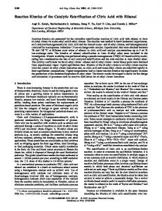
2. Model Equations Mathematical modelling in Engineering is used to study the dynamics of real life process. It plays an important role over the years to achieve better design and understanding the dynamic behaviour of the systems. Before any optimisation or control can be implemented, the models have to be in place and give a fair representation of the system to be studied. In general, batch distillation is an unsteady state process. The model describing a batch distillation column is always dynamic in nature and results in a system of ordinary differential equations (ODEs) or a coupled system of differential and algebraic equations (DAEs). The detailed dynamic model for an n-stage batch reactive distillation column (Figure1) consists of unsteady state mass and energy balance equations. It includes column holdup, rigorous phase equilibria, and chemical reaction on the plates, in the reboiler and in the condenser. The stages are counted from top to bottom. The main assumptions used in the model are: 1. 2. 3. 4. 5. 6. 7. 8. 9.
Negligible vapour holdup. Adiabatic plates. Constant molar holdup on plates and in the condenser. Perfect mixing of liquid and vapour on plates. Fast energy dynamics. Constant operating pressure. Total condensation with no subcooling. Chemical reaction on the plates, in the reboiler and in the condenser. Feed mixture at its bubble point.
Reactor and Reboiler
Figure 1. Batch Reactive Distillation Column (Conventional Column)
3
E.A. Edreder et al.
2.1. Model Equation for Batch Reactive Distillation Column With reference to the column configuration given in Figure 1 the model equations involved are presented below: 2.1.1. Condenser and Distillate Accumulator j =1: •
Accumulator Total Mass Balance:
dH a = LD dt
(1)
• Component Mass Balance
a) Accumulator Ha
dx a i = LD ( x D i − x ai ) dt
(2)
b) Condenser Holdup Tank Hc
dx D i = V2 y 2 + r1 i H c − (V2 + ∆n1 H c ) x D i dt •
(3)
Energy balance V
L
0 = V2 h2 − (V2 + ∆n1 H c ) h1 − QC •
(4)
Other Equations
L1 = R (V2 + ∆n1 H c )
(5)
L D = (V2 + ∆n1 H c ) (1 − R )
(6)
T1 = T1 ( x D i , P )
(7)
h1 = h1 ( x D i , T1 , P )
L
L
(8)
r1i = r1i (k r , x D i )
(9)
∆n = Σr ji
(10)
4
Performance of esterification system in reaction-distillation column
2.1.2. Internal Plates j= 2 to N-1
•
Total Mass Balance (11)
0 = L j −1 + V j +1 − L j − V j + ∆n j H j
• Component Mass Balance Hj
dx j dt
•
(12)
= L j −1 x j −1 + V j +1 y j +1 − L j x j − V j y j
Energy balance
0 = L j −1 h L j −1 + V j +1hV j +1 − L j h L j − V j h V j
•
(13)
Equilibrium
y ji = K ji x ji •
(14)
Restrictions:
Σ y ji = 1
(15)
Relations defining Physical Properties and Chemical Reactions
K ji = K ji ( y ji , x ji , T j , P)
(16)
hj L = hj L ( x j i , T j , P )
(17)
h j = h j ( y j i , T j , P)
V
V
(18)
r j i = r j i (k r , x j i )
(19)
∆n j = Σ r j i
(20)
2.1.3. Reboiler: j = N
•
Total Mass Balance
dH N = L N −1 − V N + ∆n N H N dt
(21)
5
E.A. Edreder et al.
• Component Mass Balance HN
dx N = L N −1 ( x N −1,i − x N ,i ) + V N ( y N − x N ,i ) + rN H N − ∆n N H N x N i (22) dt •
Energy balance
0 = LN −1 (h L N −1 − h L N ) + V N (hV N − h L N ) + QR
(23)
The other equations for the reboiler are similar to Equations (16-20) where j is replaced by N
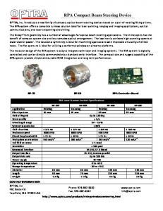
Figure 2. Semi-batch Reactive Distillation Column (Unconventional Column)
2.2. Mathematical Model of the Semi-Batch Reactive Distillation Referring to Figure 2 for semi-batch distillation column, the accumulator, condenser, and reboiler equations in the detailed dynamic model presented in Section 2.1 will remain the same. The model equations for the intermediate plates are presented below: 2.2.1. Internal Plates j= 1 to N (N, Intermediate Plates)
• 0= Lj
Total Mass Balance −1
(24)
+ V j +1 − L j − V j + F j + ∆n j H j
6
Performance of esterification system in reaction-distillation column
• Component Mass Balance Hj
dx j dt
•
= Lj
x + V j +1 y j +1 − L j x j − V j y j + x f F j −1 j −1
Energy balance
0 = L j h L j −1 + V j + 1 h V j + 1 − L j h L j − V j h V j + h f F j −1
•
(26)
Equilibrium
y ji = K ji x ji •
(25)
(27)
Restrictions:
Σ y ji = 1
(28)
Relations defining Physical Properties and Chemical Reactions
K ji = K ji ( y ji , x ji , T j , P )
(29)
hj L = hj L ( x j i , T j , P)
(30)
V
V
h j = h j ( y j i , T j , P)
(31)
h f = h f ( x f i , T f , P)
(32)
r j i = r j i (k r , x j i )
(33)
∆n j = Σ r j i
(34)
2.3. gPROMS Modeling Tool In this work gPROMS (general Process Modelling System) (2004) modelling software is used to develop the process model. It is a powerful general purpose modelling and optimisation environment, used to enhance the design and operation of continuous and dynamic processes. gPROMS has a number of advanced features including the ability to estimate an unlimited number of parameters and to use data from multiple steady-state and dynamic experiments. It also gives the user complete flexibility in that they can 7
E.A. Edreder et al.
specify different variance models for different variables in different experiments. Moreover, it has a built-in interface to MS Excel that allows the user to automatically test the statistical significance of results, generate plots overlaying model data and experimental data, plot confidence ellipsoids. Typical application areas by using gPROMS are those that involve complex physical and chemical phenomena, such as reaction engineering, crystallisation and complex separation processes.
3. Optimisation Problem Formulation and Solution The optimisation of a batch column can be depicted as a process consisting of three stages. The first stage models the process by using appropriate equations. The second stage selects an objective function that describes the performance of the system. The third stage identifies an appropriate algorithm to solve the optimisation problem subject to design and operation constraints. Three categories of batch distillation optimisation problems are found in the literature: 1. Maximum Distillate Problem which aims at maximizing the quantity of distillate recovered with a given purity in a given time. 2. Minimum Time Problem which aims at minimizing the total operation time to produce a given quantity of distillate with a given purity. 3. Maximum Profit Problem which aims at optimizing an economic cost function to include many contributions like the total operation time, the quantity of distillate, and its purity. In this section, we consider the maximum conversion problem for conventional and unconventional (semi-batch configuration) batch reactive distillation processes, subject to product purity constraints (purity of ethyl acetate 0.7 molefraction). For conventional operation the piecewise constant reflux ratio is selected as control parameter to be optimised for a fixed batch time (between 15 to 25 hrs) so as to maximise the conversion of the limiting reactant (ethanol) while the reflux ratio and the amount of acetic acid feed rate are optimised for semi-batch operation. The most common constraints in batch distillation are on the amount and on the purity of the product at the end of the process or at some intermediate point in time. This section is divided into two parts. In the first part (Section 3.1), we consider the optimisation problem of batch reactive distillation column in terms of maximum conversion of limiting reactant (ethanol). In the second part (Section 3.2) of this section, we consider the maximum conversion problem for semi-batch distillation column.
8
Performance of esterification system in reaction-distillation column
3.1. Conventional Batch Distillation Referring to Figure 1 for batch reactive distillation columns, the optimisation problem can be stated as:
Given:
Determine: So as to maximise: Subject to:
the column configuration, the feed mixture, condenser vapour load, a separation task (i.e. achieve the product with purity specification for a key distillate component) and the batch time. the optimal reflux ratio profile R(t) an objective function defined for instance the conversion. equality and inequality constraints.
Mathematically the optimisation problem (OP1) can be written as: OP1
Max
X
R subject to :
(35)
x AcOEt ≥ x *AcOEt
and
f (t , x ', x, u, v) = 0
(mod el equation)
with
f (t0 , x '0 , x0 , u0 , v) = 0 (initial condition)
Where X is the conversion of the limiting reactant (ethanol) to product (ethyl acetate), rf is reflux ratio and xAcOEt is the composition of ethyl acetate in the product at final time tf and x*AcOEt is the desired composition of ethyl acetate.
3.2. Semi-batch Reactive Distillation Mathematically the optimisation problem (OP2) can be represented as: OP 2
Max R, F subject to :
X xAcOEt ≥ x *AcOEt l
and
F ≤ F ≤ Fu f (t , x ', x, u , v) = 0
with
f (t0 , x '0 , x0 , u0 , v) = 0 (initial condition)
(inequality constra int) (mod el equation)
(36)
Where F is the acetic acid feed rate.
3.3. Operating Constraint Since the feed mixture is charged in the reboiler to its maximum capacity at the beginning of the process. For a given condenser vapour load Vc, if the reflux ratio R (which governs the distillate rate, LD, kmol /hr) and the feed rate F (kmol / hr) are not carefully controlled, the column will be flooded. The reboiler will overflow and will push the liquid up the column which will disturb the column hydraulics. The following constraint must be satisfied to avoid column flooding (Mujtaba, 1999). 9
E.A. Edreder et al.
LD ≥ F Where, LD = Vc (1 − R ) This leads to: R ≤ 1 − ( F / Vc ) and Rmax = 1 − ( F / Vc )
(37)
4. Case study 4.1. Reaction Kinetics &VLE The reaction between the acetic acid (AcOH) and ethanol (EtOH) for the production of ethyl acetate (AcOEt) and water (H2O) is exothermic reversible and represented as:
AcOH (1) + EtOH (2) ⇔ AcOEt (3) + H 2 O(4)
(38)
The reaction rate equation for a reversible esterification using hydrochloric acid as catalyst (Smith, 1956) is represented as: (39)
ri = k f C AcOH C EtOH − kr C AcOEt CH 2O
The forward (kf) and backward (kr) reaction rate constants used in Eq. (4) are: kf = 4.76 x 10⁻⁴ and kr = 1.63 x 10⁻⁴ litter/gmol-min (Mujtaba and Macchietto,1997), Ci is the component concentration in gmol/litter. The Ki vapour-liquid equilibrium coefficients (VLE) were calculated according to the method proposed by Suzuki et al. (1970) for system containing four components on each plate. It can be written as follows:
K1 = 2.25 X 10⁻² T - 7.812
T > 347.6 Kelvin
(40)
K1 = 0.001 < 347.6 logK2 = -2.3 X 10³ / T + 6.588 log K3 = -2.3 X 10³ / T + 6.742 log K4 = -2.3 X 10³ / T + 6.484 4.2. Problem Specifications The amount of feed (kmol): (acetic acid, ethanol, ethyl acetate, water) for different cases are shown in Table 1. The amount of initial charge to the reboiler for semi-batch column is the same as the base case feed. The other input data for this case are presented in Table 2. The liquid and vapour enthalpies and other physical properties 10
Performance of esterification system in reaction-distillation column
such as densities are calculated using (IPPFO) which is linked with gPROMS modelling software. Table 1. Amount of Feed (kmol) for Different Cases Component Base Case Case 1 Case 2 Acetic acid 2.250 2.375 2.500 Ethanol 2.250 2.125 2.000 Ethyl acetate 0.000 0.000 0.000 Water 0.500 0.500 0.500 Total 5.00 5.00 5.00
Case 3 2.625 1.875 0.000 0.500 5.00
Case 4 2.500 2.250 0.000 0.250 5.00
Table2.Column specifications for ethanol esterification process No of ideal stages Internal plate hold up (kmol) = 0.0125 (including reboiler and condenser) = 10 Condenser hold up (kmol) = 0.10 Feed Location (Semi-batch) = 8 Vapour boil up rate (kmol/hr) = 2.50 Total fresh feed (kmol) = 5 Column pressure (bar) = 1.013
5. Results and Discussions The plate compositions, product accumulator compositions and reboiler compositions are the differential variables of the model equations. To ensure the consistent initialisation of the differential and algebraic equations (DAEs) system we assume that at t=0, these variables are equal to the feed compositions. The performances of batch (conventional) and semi-batch (unconventional) reactive distillation are evaluated based on the maximum conversion of ethanol to ethyl acetate. Optimisation problems (Equations 35 and 36) are formulated for both processes to maximise the conversion subject to satisfaction of ethyl acetate purity (0.7 mole fraction) in the distillate product
5.1. Results and Discussions for Conventional Column The optimisation problem OP1 is considered and solved with varying batch time (between 15 to 25 hrs) while optimising the piecewise constant reflux ratio subject to product purity 0.7 molefraction of ethyl acetate. The optimisation results in terms of maximum conversion, amount of product (ethyl acetate) collected for each case and optimal reflux ratios are presented in Tables 3, 4 and Figure 3 respectively. It can be seen from Table 3 that as the batch time increases the conversion at given product purity increase for all the cases because as the product species are withdrawn by distillation and there is more time available, the reaction goes further to the right. Moreover the conversion has been improved with changing feed amount (including the case with the reduced amount of water in the feed).
11
E.A. Edreder et al.
Table 3. Maximum Conversion of Ethanol (%) at Different Batch Time tf, hr Base case Case 1 Case 2 Case 3 15 69.9 72.8 75.2 77.2 16 71.0 73.8 76.2 78.1 20 74.9 77.0 79.3 81.2 25 76.9 79.7 81.9 83.7
Case 4 73.7 74.7 77.8 80.5
Table 4. Amount of Product at Different Batch Time and Product Purity of 0.7 tf, hr Base case Case 1 Case 2 Case 3 Case 4 15 2.14 2.14 2.10 2.04 2.32 16 2.20 2.20 2.15 2.09 2.37 20 2.37 2.36 2.30 2.21 2.53 25 2.50 2.46 2.39 2.30 2.65
0.97 0.965
Reflux Ratio
0.96 0.955 Base Case Case 1 Case 2 Case 3 Case 4
0.95 0.945 0.94 0.935 14
16
18
20
22
24
26
28
30
Time (hr)
Figure 3 Optimal Reflux Ratio Profile for all cases at product purity = 0.7.
The results in Table 4 clearly show that the amount of product increases with increasing batch time for all cases. Furthermore the higher amount of product was obtained in Case 4 (with reducing amount of water in the feed) compared to the base case for all operation time. It can be seen from Figure 3 that the optimal reflux ratio increases with increasing batch time for all the cases. Figure 3 also shows that the Case 1 can be operated at same optimal reflux ratio for the base case but the Cases 2 and 3 operated with higher
12
Performance of esterification system in reaction-distillation column
reflux ratio compared with the base case. The column can operate at lower reflux ratio (compared to the base case) with reducing amount of water in the feed (Case 4).
5.2. Results and Discussions for Semi-batch Column The maximum conversion problem is solved again for fixed batch time (between 15 to 25 hrs) and given product (ethyl acetate) purity 0.7 molefraction. One constant reflux ratio level together with the rate of acetic acid feed is optimised. The column specifications are shown in Table 2 and the amount of initial charge to the reboiler is similar to the base case (Table 1). Pure acetic acid is charged at the rate of F = 0.12 kmol/hr to the column. Since the column is operating with full charge, constraints given by equation (37) must be satisfied to avoid column flooding. The optimal results in terms of maximum conversion, amount of product (ethyl acetate) and optimal reflux ratio profile are summarised in Table 6 for different batch times and product purity 0.7 molefraction of ethyl acetate. Table 6 Optimal Results for Semi-batch Operation Case Study tf , hr Maximum conversion Optimal Reflux Ratio Amount of Product, % kmol 15 76.7 0.936 2.40 16 77.9 0.939 2.46 20 81.6 0.947 2.65 25 It can be seen clearly from Table 6 that both the maximum conversion achieved and amount of product (ethyl acetate, kmol) increases when the column is operated in semi-batch scheme up to batch time 20 hrs. No solution was found for batch time 25 hrs as the reflux ratio needed was higher than the maximum allowable reflux ratio (Rmax) to avoid the column flooding.
5.3. Comparison between Conventional and Unconventional Column(semi-batch ) To simplify the comparison between conventional and unconventional (semi-batch) column, the feed of the base case and the column specifications in Table 2 are considered. Optimal results using conventional operation and semi-batch operation for the base case which are presented in Tables 3 and 6 shows about 10 % more conversion and lower reflux ratio are achieved when the column is operated in semibatch scheme compared to that obtained by conventional column up to batch time of 20 hrs. Also for a given batch time, semi-batch operation produces more distillate product.
13
E.A. Edreder et al.
6. Conclusions In this study, the esterification process of acetic acid with ethanol producing ethyl acetate and water is modelled using detailed mass and energy balances and thermodynamic properties within gPROMS modelling software. The performances of batch (conventional) with varying amount of reactants and semibatch (unconventional) reactive distillation are evaluated in terms of maximum conversion of ethanol to ethyl acetate. Optimisation problems are formulated for both processes to maximise the conversion while optimising the reflux ratio for the first process and both the reflux ratio and feed rate of acetic acid for the second process subject to satisfaction of ethyl acetate purity (0.7 mole fraction of ethyl acetate) in the distillate product. Piecewise constant reflux ratio profile was considered for the conventional column and the optimisation problem was solved with varying batch time (between 15 to 25 hrs). For semi-batch operation, one constant reflux ratio level together with of the rate of acetic acid feed is optimised. The optimisation results show that the conversion has been improved with changing initial feed amount (including the case with the reduced amount of water in the feed) by about 5%. For a given batch time, semi-batch operation produces more distillate product by about 10%. The column can operate at lower reflux ratio (compared to the base case) with reducing amount of water (Case 4) and with semi-batch case. It is found also that there are cases when semi-batch operation can be more effective in maximising the conversion.
Nomenclature LD distillate flow rate (kmol/hr) Ha, Hc accumulator and condenser holdup respectively (kmol) Hj , HN plate and reboiler holdup respectively (kmol) liquid, vapour enthalpy (kJ/kmol) hL, hV L, V liquid, vapour flow rates in the column (kmol/hr) N number of plates Ci stands for concentration in gmol/litter for the ith component QC , QR condenser or reboiler duty (kJ/hr) T, P temperature (K), pressure (bar) K vapour-liquid equilibrium constant reflux Ratio R, Rmax F feed of semi-batch (kmol/hr) r reaction rate t batch time (hr) x, y liquid or vapour composition (mole fraction) xa accumulated distillate composition (mole fraction) xD instant distillate composition (mole fraction) ∆n change in moles due to chemical reaction AcOH acetic acid EtOH ethanol EtOAc ethyl acetate 14
Performance of esterification system in reaction-distillation column
H2 O
water
Superscripts and subscripts i component number j stage number Greek letters ρ Molar density (kmol /litter)
References Albet, J., Le Lann, Joulia, X. and Koehret, B., (1991), Proceedings ComputerOriented Process Eng, Elsevier Science Publisher B.V., Amsterdam, p75 Balasubramhanya, L.S. and Doyle III, F.J., (2000), Journal of Process Control, 10, (2-3), 209–218. Basualdo M.S. and Ruiz C., (1995), Latin American Applied Research, 25S, 29. Bogacki, M.B., Alejski, K. and Szymanowski, J., (1989), Computers & Chemical Engineering, 13(9), 1081. Cuille, P.E., and Reklaitis, G.V., (1986), Computers & Chemical Engineering, 10(4), 389. Doherty, M. F. and Buzad, G., (1992), Trans IChemE, 70, 448. Egly, H., Ruby, V. and Seid, B., (1979),Computers & Chemical Engineering, 3, 169. gPROMS. (2004). gPROMS Advanced User Guide. Process Systems Enterprise Ltd., London. Giessler S., Hasebe S., and Hashimoto I., (2001) J. Chem. Engng. Japan, 34(3), 312. Mujtaba I.M. and Macchietto S., (1992) AIChE Annual Meeting. Mujtaba I.M. and. Macchietto S., (1994) Proc. IFAC Symposium ADCHEM’94, Kyoto, pages 401–406. Mujtaba I.M, Macchietto S., (1997) Ind. Eng. Chem. Res. 36, 2287. Mujtaba, I.M., (1999) Trans. IChernE, 77A, 588. Mujtaba, I. M., (2004) Batch distillation: Design and operation. London: Imperial College Press.
15
E.A. Edreder et al.
Patel R., Singh K., Pareek V. and Tade M., (2007), Chemical Product and Process Modelling. Vol.2-issue 2 Article 1. Reuter, E., Wozny, G. and Jeromin, L., (1989) Computers & Chemical Engineering 13, 499-510. Suzuki, I., Yagi, H., Komatsu, H. and Hirata, M., (1970). J. Chem. Engng Japan 3, 152-157 Taylor, R., and Krishna, R., (2000), Chem. Eng. Sci., 55, 5183-5229. Wajge R.M. and. Reklaitis G.V., (1999), Chem. Eng. Journal, 75(1), 57–68. Wilson, J.A., (1987), IChemE Symposium Series No.100, p 163.
16