applied widely and it is a suitable system to treat the acid wastewaters [11, 12]. ..... passive treatment wetland: A case study from Lambert Run, West Virginia, ...
International Journal of Advances in Engineering & Technology, Jan., 2015. ©IJAET ISSN: 22311963
PERFORMANCE OF THE HORIZONTAL SUBSURFACE-FLOW CONSTRUCTED WETLANDS WITH DIFFERENT OPERATIONAL PROCEDURES *Nopi Stiyati Prihatini1,2Bambang Joko Priatmadi3, Aniek Masrevaniah4, Soemarno5 1
Doctoral Program of Environmental Studies, University of Brawijaya, Malang, Indonesia 2 Environmental Engineering Department, Fac. of Engineering, University of Lambung Mangkurat, Banjarmasin, Indonesia 3 Soil Sciences Department, Fac. of. Agriculture, University of Lambung Mangkurat, Indonesia 4 Water Resources Engineering Department, Fac.of Engineering, University of Brawijaya, Indonesia 5 Soil Sciences Department, Fac. of. Agriculture, University of Brawijaya, Malang, Indonesia
ABSTRACT One of the critical success factors in the performance of Constructed Wetlands (CW) is drain-operation of wastewater into the CW. The purpose of this study was to determine the performance of horizontal subsurfaceflow constructed wetland (HSSF-CW) in Fe removal and raise pH of AMD with the difference operations of the wastewater flow. Two kinds of the HSSF-CW were planted with the Purun tikus (Eleocharis dulcis). Purun tikus is potentially as a biofilter due to its fast grow and adapt well to the flooded acid soils. The Model-A of HSSFCW is operated in batch-flow while the Model-B is operated with continuous-flow. Dimensions of the HSSF-CW is 100 cm x 30 cm x 35 cm. Results showed that Fe-removal in the Model-B is greater (103.61 mg / day) compared to Model-A (37.69 mg / day) and the HSSF-CW Model-A is only able to raise pH as much as 0.92 units, while the HSSF-CW Model-B increases pH as much as 1.97 units. It can be concluded that the HSSF-CW Model-B has better performance as compared to the Model-A.
KEYWORDS:
Horizontal subsurface flow-constructed wetland, Purun tikus (Eleocharis dulcis), iron, acid mine drainage (AMD)
I.
INTRODUCTION
Constructed wetland (CW) is one alternative method of wastewater treatment that mimics natural processes to clean the water. Various types of aquatic plants can be integrated with this method [1, 2, 3]. Communities of microorganisms naturally live in water, rocks, soil, and plants that live in these wetlands. These microorganism communities can supply nutrients for aquatic plants, and can help the processes of elimination of pollutants from contaminated waters [4]. When compared with a conventional method of wastewater treatment using chemicals, the constructed wetland technology is simple, inexpensive, and environmental-friendly [5, 6, 7]. In general there are two types of constructed wetland based on differences in wastewater flow settings, namely: (1) surface flow (SF), and (2) subsurface flow (SSF) [8, 9, 10]. There are two types of subsurface flow constructed wetland (SSFCW) , namely vertical (VSSF) and horizontal (HSSF). Compared with the other constructed wetlands (CW), the horizontal subsurface flow (HSSF) can be applied widely and it is a suitable system to treat the acid wastewaters [11, 12]. Wastewater flows horizontally through an artificial filter layer (substrate), it is typically composed of sand or gravel, roots and rhizome of aquatic plants. On these substrates are colonies of microorganisms that form a kind of biofilms. Purification of wastewater is done through a variety of
1620
Vol. 7, Issue 6, pp. 1620-1629
International Journal of Advances in Engineering & Technology, Jan., 2015. ©IJAET ISSN: 22311963 biological processes, physics, chemistry and microbiology, including sedimentation, filtration, precipitation, adsorption, nutrient uptake by plants, decomposition of organic matter by microbes and nitrogen transformations [13, 14, 15, 16]. The CW technology is widely used to treat acid mine drainage [17, 18, 19, 20, 21, 22, 23, 24, 25]. The CW is a complex system with many components that work together, so that differences in these components affect the performance of CW. The main component determining the performance of CW is the aquatic plant species suitable to the characteristics of wastewater [26]. The CW using certain aquatic plants that are tolerant of waste water and can absorb contaminants. Purun tikus (Eleocharis dulcis) is one type of marsh plants with acid sulphate soils. Purun tikus can grow well in low pH environments[27, 28], so it is used in SSF-CW for treating AMD in this study. Research conducted by Krisdianto et al. showed that the Purun tikus can reduce the content of dissolved Fe in the wetland plots were planted with rice were given AMD coal. In this condition the Purun tikus can treat water to produce water with an average Fe content of 1.1766 mg.L-1 and Total Dissolved Solid (TDS) by an average of 0.4505 mg.L-1. In addition, Purun tikus including aquatic plants that have a very broad spectrum of habitats, and relatively rapid growth [29]. South Kalimantan is a province in Indonesia, which has the high potential for very large coal mines. Coal mining method employed by the mining companies usually is the open pit mining. This open pit mining method removes the surface layer of soil (topsoil) rich in organic matter. This activity resulted in the exposure of rock layers rich in sulfur, sulfur minerals react with water and oxygen to make sulphate released into the environment. This reaction produces a acidic wastewater, known as the acid mine drainage (AMD). This AMD is rich in Fe-soluble, low pH, can cause corrosion and dissolve other heavy metals, so it is toxic to aquatic organisms. Therefore, we need an effective AMD processing technology, easier and cheaper, so that AMD does not pollute aquatic environment. The technology of CW planted with the Purun tikus is expected feasible to treat AMD sufficiently. The most important operational factor of CW is the flow of wastewater, hydraulic loads, and detention time [30]. ). Based on the wastewater flows, it can be divided into the batch flow and continuous flow. In the batch flow system, CW is supplied with wastewater over a period of time and after that no additional wastewater [31]. In the continuous flow system, the wastewater flows continuously into the CW [30, 31]. This study was conducted to determine the performance of horizontal subsurface constructed wetland (HSSF-CW) with Purun tikus aquatic plant in removing soluble-Fe and raising pH of AMD, involving the batch flow system and the continuous flow system. In this paper, we begin with description of constructed wetland and its used for treating acid mine drainage, and then the importance of flow-operation of wastewater in performance of CW. We compare the result measured parameters between models and finally, conclute the best model.
II.
RESEARCH METHODS
Constructed Wetland (CW) used in this study is the CW-type of Horizontal Subsurface Flow (HSSF) with two kinds of wastewater flowing ways, namely: batch-flow and continuous-flow. The reactor is made of wood and covered with plastic-film with a size of 100 cm x 30 cm x 35 cm (Figure 1). The media used are acid sulfate soils from the Central Puntik Village, South Kalimantan, which is a natural habitat for Purun tikus. Thickness of soil for plant growth media in each reactor is 30 cm. In this study, the HSSF-CW are planted with Purun tikus (Eleocharis dulcis) (Figure 1). Seedlings planted are tillers with an average height of 15 cm, the seedlings were planted at a distance of 10 cm.
1621
Vol. 7, Issue 6, pp. 1620-1629
International Journal of Advances in Engineering & Technology, Jan., 2015. ©IJAET ISSN: 22311963
Figure 1. Purun tikus tillers (Eleocharis dulcis)
The Model-A reactor is operated with the batch flow system. Wastewater inffluent as much as 22 liters flowed into the reactor at the beginning of the process without adding more in the span of 15 days. In the Model-B reactor, inffluent flowed continuously with the flow rate (5 L / day) within a period of four days.
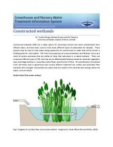
A = influent reservoir B = inlet pipe C = gravel D = growth media E = purun tikus F = gravel G = outlet pipe H = effluent reservoir
Figure 2.
Design Reaktor HSSF- Contructed Wetland Inffluent of AMD comes from coal mining areas in South Kalimantan. Parameters measured in this study are pH and concentration of soluble-Fe (dissolved Fe). Measurement of pH using a pH meter. Concentration of dissolved-Fe in the wastewater is analyzed using the Atomic Absorption Spectrophotometer (AAS). HSSF-CW performance is measured by the amount of soluble-Fe were removed (Fe-rem.) per day by the SSF-CW system [19, 32]. It is formulated: Fe (mg/day)rem = Fe(mg/day)in – Fe (mg/day)out
III.
RESULTS AND DISCUSSION
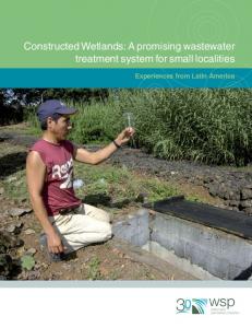
3.1.The role of aquatic plant in removing soluble Fe in the HSSF-CW system Results showed differences between the HSSF-CW without Purun tikus and the HSSF-CW planted with Purun tikus (Figure 3). The concentration of dissolved-Fe in effluents of the HSSF-CW Model-A and Model-B is lower than the HSSF-CW Control. This suggests that Purun tikus aquatic plant played a significant role in the process of removal dissolved-Fe from acid mine drainage. Purun tikus supplied oxygen necessaried in oxidizing and precipitating iron substances, and Purun tikus are also
1622
Vol. 7, Issue 6, pp. 1620-1629
International Journal of Advances in Engineering & Technology, Jan., 2015. ©IJAET ISSN: 22311963
250
Fe concentration (mg/L)
Fe concentration (mg/L)
able to absorb the amount of iron for their metabolism [3] Both of these processes is estimated to be the cause of lower concentrations of dissolved-Fe in the effluent of the HSSF-CW with Purun tikus compared to the HSSF-CW without plants. The importance of plants in the HSSF-CW systems have been shown by research results of Wiessner et al. [33].
200 150
control
100
Model A
50 0 0
5
10 15 time (days)
40 35 30 25 20 15 10 5 0
control Model B
0
20
2 4 time (days)
6
Figure 3. Fe Concentration Fe of AMD effluents in the HSSF-CW control (without vegetation), Model-A (vegetated with batch flow), Model-B (vegetated with continuous flow)
3.2.Fe concentration of AMD in the Horizontal Subsurface Constructed Wetland
Fe concentration (mg/L)
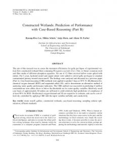
The HHSF-CW Model-A is operated with the batch flow system. The entire wastewater is supplied into the reactor at the beginning of the process, no additional wastewater else into the reactor [31], The concentration of pollutants (dissolved-Fe) decreased following the function of time [26]. Increasing concentration of the dissolved Fe in effluents during the first ten days (Figure 4) due to acid mine water that has a low pH resulted in increased desorption of Fe and enhanced solubility of Fe substances. While the declining concentrations of the dissolved Fe occurs in the next five days, the Purun tikus plants have started to absorb dissolved Fe in AMD. Fe++ ions can be absorbed directly by the root system together with water absorption. A number of Fe++ reacted with the organic substances (chelating agents) excreted by plant roots into Fe-chelate compounds that can be absorbed by plants. Along with the growth of plants, processes of Fe absorption from AMD would be continued [34]. 120 100 80 60
y = -0.8088x2 + 15.761x + 28.909 R² = 0.9721
40 20 0 0
5
10
15
20
time (days) Figure 4. Fe concentration of AMD in the HSSF-CW Model-A
Much of the research on constructed wetlands focused on the input-output (I/O) data, so that the regression equation becomes a useful tool in the interpretation of the I/O data [13]. Data were analyzed using regression methods to predict the quality of effluents. Results of the regression analysis between the x (time) and y (Fe concentration) showed the regression equation (1): Y = -0,8088x2+15,761x+28,909...(R²=0,9721**) Result of analysis showed a significant relationship between the variables x and y, and the regression equation can be used to predict Fe-concentration in AMD effluents by time.
1623
Vol. 7, Issue 6, pp. 1620-1629
Fe concentration (mg/L)
International Journal of Advances in Engineering & Technology, Jan., 2015. ©IJAET ISSN: 22311963 120 100 80 60 40
28.91
20
20.61 3.21
0 0
2
4
6
8 10 12 14 16 18 20 time (days)
Figure 5. Prediction of Fe concentration of AMD in the HSSF-CW Model-A.
Figure 5 shows the change of Fe concentration in effluents from the HSSF-CW Model-A, which is estimated based on the regression equation. Fe concentration in effluents is lower than the Fe concentration in inffluents (28.909 mg/L). On day of 20 and 21, Fe-concentration in effluents have met the quality standard of mining wastewater (Standard of Fe is 7 mg/L) [35]. Changes of Fe concentrations in effluents from the HSSF-CW Model-B is shown in Figure 6. The Fe concentrations decreased very significantly by the fourth day (8.86 mg/L), but still not meet yet the quality standard of Fe. Based on these values, the regression equation (2) can be derived: Y = -4,1442x + 25,44………..(R² = 0.999**) Fe concentration (mg/L)
30 25.44
25
y = -4,1442x + 25,44 R² = 0.999
20 15 10
8.86
5 0 0
2
time (days)
4
6
Figure 6. Fe consentration of AMD in the HSSF-CW Model-B
Fe concentration(mg/L)
This regression equation can be used to predict Fe concentration in effluents from the HSSF-CW Model-B, as shown in Figure 7. On the fifth day 5, Fe concentration is predicted at 4.719 mg/L, it has met the water quality standard of wastewater. 30 25 20 15 10 5 0
25.44
4.719 0
1
2
3 4 time (days)
5
6
Figure 7. Prediction of Fe consentration of AMD in the HSSF-CW Model-B.
3.3.pH change of AMD in the Horizontal Subsurface Constructed Wetland pH is one of the quality parameters of coal mining wastewater. Acid mine drainage (AMD) discharged into a body of water should be the pH of 6 - 9. In this study, pH is used to measure performance of the Horizontal Subsurface Flow Constructed Wetland (HSSF-CW). Change of pH of
1624
Vol. 7, Issue 6, pp. 1620-1629
International Journal of Advances in Engineering & Technology, Jan., 2015. ©IJAET ISSN: 22311963 the AMD during the study of HSSF-CW with Purun tikus were shown in Figure 8 (HSSF-CW ModelA) and in Figure 9 (HSSF-CW Model-B). 4 3 y = 0,0006x3 - 0,0195x2 + 0,2218x + 2,5 R² = 0.999
pH
2 1 0 0
5
10 time (days)
15
20
Figure 8. pH values of AMD in the HSSF- CW Model-A 6
5 4
y = 0,4917x + 3 R² = 0.999
pH
3 2 1 0 0
2 time (days)
4
6
Figure 9. pH values of AMD in the HSSF-CW Model-B.
pH
Results of pH measurements are regressed to detention time (days), it is suggested the regression equations: y = 0,0006x3 - 0,0195x2 + 0,2218x + 2,5 …..(3) y = 0,4917x + 3……………………………….(4) The equation (3) is a regression equation of detention time with a pH of effluents in the HSSF-CW Model-A, and the equation (4) in the HSSF-CW Model-B. The correlation coefficient in equation (3) and (4) are R² = 0.9999 ** , which means that the relationship of pH with detention time in the two models are very significant and the regression equations can be used to predict the pH of effluents. Based on these equations can predict the time required by the HSSF-CW with Purun tikus to treat AMD in meeting the wastewater quality standard (pH = 6-9) [35]. The prediction results by using equation (3) and (4) show that the HSSF-CW ModelA takes 27 days (Figure 10) in meeting the quality standards. While the HSSF-CW Model-B only takes seven days (Figure 11). This suggests that performance of the HSSF-CW Model-B is better than the HSSF-CW Model-A. 7 6 5 4 3 2 1 0
6.08
2.5
0
3
6
9
12 15 18 21 24 27 30 time (days)
Figure 10. Prediction of pH values of AMD in the HSSF- CW Model-A
1625
Vol. 7, Issue 6, pp. 1620-1629
pH
International Journal of Advances in Engineering & Technology, Jan., 2015. ©IJAET ISSN: 22311963 7 6 5 4 3 2 1 0
6.44
3
0
2
4 time (days)
6
8
Figure 11. Prediction of pH values of AMD in the HSSF-CW Model-B.
3.4.The CW Performance The CW performance can be evaluated based on its ability in reducing levels of pollutants or in improving quality parameters [36]. The CW performance is usually expressed in the efficiency rate or the efficiency percentage (%). However, value of this efficiency can not explain how much iron or other pollutants removed per unit or time or per unit or surface area of the constructed wetland. Therefore, in this study , performance of the CW is determined based on the amount of iron removed per unit of time (days) [19]. Table 1. Performance of the HSSF-CW in removing Fe from AMD Model
Fe (mg/hari) Fe In
Fe Out
Fe rem
A
42,40
4,71
37,69
B
127,20
23,60
103,61
Performance of the Horizontal Subsurface Flow Constracted-Wetland (HSSF-CW) planted with Purun tikus in removing soluble-Fe is summarized in Table 1. Performancve of the Model-B is better in comparison to the Model-A. This is indicated by the amount of Fe-removal in the Model-B is greater (103.61 mg / day) compared to Model-A (37.69 mg / day); and the time required in removing soluble Fe in the HSSF-CW Model-B is only five days (Figure 7), while the Model-A requires 21 days (Figure 5). In addition to the concentration of soluble-Fe, the Indonesian government regulations also required pH as the quality parameter of coal mine wastewater (AMD). Results of pH measurements (Table 2) show that the performance of HSSF-CW Model-B is better in raising pH compared to HSSF-CW Model-A. During periode of 15 days the HSSF-CW Model-A is only able to raise pH as much as 0.92 units, while the HSSF-CW Model-B increases pH as much as 1.97 units within four days. However, pH value of effluents on the HSSF-CW Model-B is still unable to meet the water quality standards set by the Indonesian government [35]. Table 2. Performance of the HSSF-CW in raising Fe of the AMD pH
Model HSSF CW
Influent
Effluent
Increment
A
2,50
3,42
0,92
B
3,00
4,97
1,97
Some researchers have argued that the CW-operated with the batch flow system can improve the pollutant removal capacity [37, 38], especially for the CW that treated domestic wastewater [39]. However, research of Burgoon et al. (1995), suggested that the batch flow system is as good as the continuous flow system [40]. Results of research in South Kalimantan showed that batch flow system of HSSF-CW suggested similar performance to the continuous flow system of HSSF-CW. This is caused by the removal of metals (including iron) from the wastewater in the wetland system is determined by interaction of the deposition process, sedimentation, sorption, co-precipitation, cation-
1626
Vol. 7, Issue 6, pp. 1620-1629
International Journal of Advances in Engineering & Technology, Jan., 2015. ©IJAET ISSN: 22311963 exchange, photodegradation, phytoaccumula-tion, biodegradation, and uptake by plants [21]. In the batch flow system, the water-saturated media suggested no space to free oxygen. Free oxygen is required to oxidixe ferrous compounds into the ferric compounds and it is precipitated. In contrast to the continuous flow system, the wastewater is not put into the reactor at the same time, thus providing the opportunity for oxidation to take place better. Soil as a growing medium of plants and microbes influence the processes of hydraulic and affect the performance of the system CW. This soil is the main support material for the growth of plants and microbes. Interaction among plants, microbes and soil substrate produce the complex processes that occur in the rhizosphere, it is roled in the pollutant removal from AMD [3].
IV.
CONCLUSION
Model of the Horizontal Subsurface Flow Constructed Wetlands-(HSSF-CW) with the Purun tikus plant capable of removing iron and raising pH of the acid mine drainage. Performance of the HSSFCW Model-A in Fe removal and raising pH is smaller than the HSSF-CW Model-B. It can be concluded that the HSSF-CW Model-B with a continuous wastewater flow has better performance as compared to the HSSF-CW Model-A with batch flow.
V.
FUTURE WORK
Based on the result from this study, in the future it’s needed to examine performance of HSSF-CW with a continuous wastewater flow on pilot project and field project.
REFERENCES [1]. Adcock, P.W. and G.G. Ganf., 1994, Growth characteristics of three macrophyte species growing in a natural and constructed wetland system, Water Science and Technology, 29, pp 95-102. [2]. Tanner, C.C., 1996, Plants for constructed wetland treatment systems - A comparison of the growth and nutrient uptake of eight emergent species, Ecological Engineering, 7(1), pp 59-83. [3]. Stottmeister, U., et al., 2003, Efects of Plants and Microorganisms in Constructed Wetlands for Wastewater Treatment, Biotechnology Advances, 22, pp 93-117. [4]. Zhao, Y.J., et al., 2012, Influence of the plant development on microbial diversity of vertical-flow constructed wetlands., Biochemical Systematics and Ecology, 44, pp 4-12. [5]. Mburu, N., et al., 2013, Performance comparison and economics analysis of waste stabilization ponds and horizontal subsurface flow constructed wetlands treating domestic wastewater: A case study of the Juja sewage treatment works, Journal of Environmental Management, 128, pp 220-225. [6]. Guittonny-Philippe, A., et al., 2014, Constructed wetlands to reduce metal pollution from industrial catchments in aquatic Mediterranean ecosystems: A review to overcome obstacles and suggest potential solutions., Environment International, 64(1-16). [7]. Lakatos, G., et al., 2014, The management and development of constructed wetlands for treatment of petrochemical waste waters in Hungary: 35 years of experience, Ecohydrology & Hydrobiology, 14(1), pp 83-88. [8]. Hoffmann, H., et al., 2011,Technology review of constructed wetlands. Subsurface flow constructed wetlands for greywater and domestic wastewater treatment, Federal Ministry for Economic Cooperation and Development; Deutsche Gesellschaft für Internationale Zusammenarbeit (GIZ) GmbH Sustainable sanitation - ecosan program: Germany. [9]. USEPA, 1993,Handbook for Constructed Wetlands Receiving Acid Mine Drainage, USEPA: Cincinnati. [10]. Farooqi, I.H., F. Basheer, and R.J. Chaudhari. Constructed Wetland System (CWS) for Wastewater Treatment. in The 12th World Lake Conference. 2008. [11]. Kosolapov, D.B., et al., 2004, Microbial Processes of Heavy Metal Removal from Carbon-Deficient Effluents in Constructed Wetlands, Eng. Life Sci, 4, pp 403-411. [12]. O'Sullivan, A.D., D.A. Murray, and M.L. Otte, 2000in 2000 National Meeting of the American Society for Surface Mining and Reclamation: Tampa, Florida. [13]. Rousseau, D.P.L., P.A. Vanrolleghem, and N.D. Pauwa, 2004, Model-based design of horizontal subsurface flow constructed treatment wetlands: a review, Water Research, 38, pp 1484-1493. [14]. Lizama, A.K., T.D. Fletcher, and G.Sun, 2011, Removal processes for arsenic in constructed wetlands, Chemosphere, 84(8), pp 1032-1043. [15]. O.C. Türker, J. Vymazal, and C. Türe, 2014, Constructed wetlands for boron removal: A review, Ecological Engineering, 64(350-359).
1627
Vol. 7, Issue 6, pp. 1620-1629
International Journal of Advances in Engineering & Technology, Jan., 2015. ©IJAET ISSN: 22311963 [16]. Zhu, H., et al., 2014, Removal of nitrogen and COD in horizontal subsurface flow constructed wetlands under different influent C/N ratios., Ecological Engineering, 63(58-63). [17]. Kleinmann, R.L.P., 1990, Acid Mine Water Treatment Using Engineered Wetlands, International journal of mine water, 9(1-4), pp 269-276. [18]. Younger, P.L., S.A. Banwart, and R.S. Hedin, 2002, Passive Treatment of Polluted Mine Waters, Environmental Pollution, 5, pp 311-396. [19]. Hedin, R.S. and R.W. Nairn. Sizing and Performance of Constructed Wetlands: Case Studies. in Mining and Reclamation Conference and Exhibition. 1990. Charleston, West Virginia. [20]. Hedin, R.S., 2008, Iron Removal by Passive System Treating Alkaline Coal Mine Drainage, Mine Water Environ, 27, pp 200-209. [21]. Sheoran, A.S. and V. Sheoran, 2006, Heavy metal removal mechanism of acid mine drainage in wetlands: A critical review, Minerals Engineering, 19 pp 105–116. [22]. Vesper, D.J. and M.J. Smilley, 2010, Attenuation and diel cycling of coal-mine drainage constituents in a passive treatment wetland: A case study from Lambert Run, West Virginia, USA, Applied Geochemistry, 25, pp 795-808. [23]. Johnson, D.B. and K.B. Hallberg, 2005, Biogeochemistry of the compost bioreactor components of a composite acid mine drainage passive remediation system, Science of the Total Environment, 338 pp 8193. [24]. Lesley, B., H. Daniel, and Y. Paul, 2008, Iron and manganese removal in wetland treatment systems: Rates, processes and implications for management, Science of The Total Environment, 394, pp 1-8. [25]. Zhang, B.Y., J.S. Zheng, and R.G. Sharp, 2010, Phytoremediation in Engineered Wetlands: Mechanisms and Applications, Procedia Environmental Sciences, 2, pp 1315-1325. [26]. Supradata, 2005,Pengolahan Limbah Domestik Menggunakan Tanaman Hias Cyperus alternifolius L. Dalam Sistem Lahan Basah Buatan Aliran Bawah Permukaan (SSF-Wetlands) (Domestic wastewater treatment using Cyperus alternifolius L. In the SSF-wetlands system), in Environmental Resoures Management Master ProgramUniversity of Diponegoro: Semarang, Indonesia. [27]. Flach, M. and F. Rumawas, 1996, Plants Yielding Non-Seed Carbohydrates, Plant Resources of South-East Asia (PROSEA), 9, pp 97-100. [28]. Noor, M., 2004, Lahan Rawa Sifat dan Pengelolaan Tanah Bermasalah Sulfat Masam (Wetlands characteristics and management of the sulphate acid soils).Jakarta, Indonesia: PT RajaGrafindo Persada. [29]. Krisdianto, E. Purnomo, and E. Mikrianto, 2006,Peran Purun Tikus dalam Menurunkan Fe di dalam Air Limbah Tambang Batubara (Role of Purun-tikus aquatic plants in absorbing Fe from the coal acid mine drainage), Fac.of Math. and Nat. Sci.University of Lambung Mangkurat: Banjarbaru, Indonesia. [30]. Faulwetter, J.L., et al., 2009, Microbial processes influencing performance of treatment wetlands: A review, Ecological Engineering, 35, pp 987-1004. [31]. Tchobanoglos, G., F.L. Burton, and H.D. Stensel, 2003,Wastewater Engineering: Treatment and Reuse (Fourth Edition), Matcalf & Eddy, Inc, McGraw Hill Companies, Inc: New York. [32]. Davis, L., 2000,A Handbook of Constructed Wetland, in Coal Mine DrainageUSDA: Pennsylvania. [33]. Wiessner, A., et al., 2006, Effectiveness of Various Small-Scale Constructed Wetland Designs for the Removal of Iron and Zinc from Acid Mine Drainage under Field Conditions, Engineering in Life Science, 6(6), pp 548-592. [34]. Tang, S.-y., 1993, Experimental study of a constructed wetland for treatment of acidic wastewater from an iron mine in China, Ecological Engineering, 2, pp 253-259. [35]. MENLH, 2003,Indonesia Ministry of Environment Regulation No.113/2003: Wastewater standard for the Coal Mining and its Activities, Indonesia Ministry of Environment: Jakarta. [36]. Suswati, A.C.S.P. and G. Wibisono, 2013, Pengolahan Limbah Domestik Dengan Teknologi Taman Tanaman Air (Constructed Wetlands) (Municipal wastewater treatment with the Constructed wetlands), Indonesian Green Technology Journal, Vol. 2(No. 2). [37]. Schultz-Jr., R.L., 2007,Influence of Pollutant Loading Rate on Seasonal Performance of Model Constructed Wetland, in Environmental EngineeringMontana State University: Bozeman, Montana. [38]. Stein, O.R., et al., 2003, Does batch operation enhance oxidation in subsurface constructed wetlands?, Water Sci.Technol, 48(5), pp 149–156. [39]. Caselles-Osorio, A. and J. Garcia, 2007, Impact of different feeding strategies and palnt presence on the performance of shallow horizontal subsurface-flow constructed wetland, Science of The Total Environment, 378, pp 253-262. [40]. Burgoon, P.S., K.R. Reddy, and T.A. DeBusk, 1995, Performance of subsurface flowwetlands with batchload and continuous-flow conditions, Water Environ. Res., 67 (5), pp 855-862.
1628
Vol. 7, Issue 6, pp. 1620-1629
International Journal of Advances in Engineering & Technology, Jan., 2015. ©IJAET ISSN: 22311963
AUTHORS Nopi Stiyati Prihatini was born in Banjarmasin, Indonesia, in 1984. She received the Bachelor in Biology degree from the University of Lambung Mangkurat, Banjarmasin, in 2004 and the Master in Environmental Engineering degree from the Institut Teknologi Bandung, Bandung, Indonesia, in 2006. She is currently pursuing the Ph.D. degree with the Doctoral Program of Environmental Studies, University of Brawijaya, Malang, Indonesia. Her research interests include ecology, ecotoxicology, fitoremediation . Bambang Joko Priatmadi was born in Amuntai, Indonesia, in 1963. He completed a Ph.D. degree from University of Brawijaya, Malang, Indonesia. Presently he is working as Lecturer in Soil Sciences Department, Fac. of. Agriculture, University of Lambung Mangkurat, Indonesia. His research interests are soil and environment.
Aniek Masrevaniah. Completed a Ph.D degree. She is senior lecturer in Water Resources Engineering Department, Fac.of Engineering, University of Brawijaya, Indonesia. Her research interests are constructed wetland, water engineering.
Soemarno is Professor in Natural Resource Management. His permanent position is in Faculty of Soil Sciences Department, Fac. of. Agriculture, University of Brawijaya, Malang, Indonesia. His research interests Natural Resources and Environment Management.
1629
Vol. 7, Issue 6, pp. 1620-1629