Jun 25, 2018 - receiver. The phase-ambiguity in a four-phase PSK system results from the carrier recovery circuits at the receiver locking onto a wrong phase ...
https://ntrs.nasa.gov/search.jsp?R=19890016010 2018-06-25T18:29:27+00:00Z
JPL Publication 89-4, Part II
Phase-Ambiguity Resolution for QPSK Modulation Systems Part II: A Method to Resolve the Phase-Ambiguity for Offset QPSK Modulation Systems Tien Manh Nguyen
May 15,1989
NASA National Aeronautics and Space Administration
Jet Propulsion Laboratory California Institute of Technology Pasadena. California
The research described in this publication was carried out by the Jet Propulsion Laboratory, California Institute of Technology, under a contract with the National Aeronautics and Space Administration. Reference herein to any specific commercial product, process, or service by trade name, trademark, manufacturer, or otherwise, does not constitute or imply its endorsement by the United States Government or the Jet Propulsion Laboratory, California Institute of Technology.
ABSTRACT
Part I1 of this report presents a new method to resolve the phase-ambiguity for Offset QPSK modulation systems. When an Offset Quaternary Phase-Shift-Keyed (OQPSK) communications link is utilized, the phase ambiguity of the reference carrier must be resolved. At the transmitter, two different unique words are separately modulated onto the quadrature carriers. At the receiver, the recovered carrier may have one of four possible 180°, or 2 7 0 ° , referenced to the nominally phases, Oo, 90°, correct phase. The IF portion of the channel may cause a phasesense reversal, i.e, a reversal in the direction of phase rotation for a specified bit pattern. Hence, eight possible phase relationships (the so-called eight ambiguous phase conditions) between input and output of the demodulator must be resolved. Using the In-phase (I)/ Quadrature (Q) channel reversal correcting property of an OQPSK Costas loop with integrated symbol synchronization, four ambiguous phase conditions are eliminated. Thus, only four possible ambiguous phase conditions remain. The errors caused by the remaining ambiguous phase conditions can be corrected by monitoring and detecting the polarity of the two unique words. The correction of the unique word polarities results in the complete phase-ambiguity resolution for the OQPSK system.
iii
ACKNOWLEDGMENT
The author wishes to express his deep appreciation to Dr. Faramaz Davarian for his expert advice and invaluable comments on the phase-ambiguity resolution techniques for Quaternary PhaseShift-Keying (QPSK) communication systems.
PRECEDING PAGE BLANK NOT FILMED
V
CONTENTS
. . . . . . . .
I.
INTRODUCTION AND BACKGROUND.
11.
DESCRIPTION OF THE NEW METHOD FOR THE PHASE-AMBIGUITY RESOLUTION.
. . 111. SUMMARY. . . . . . . . . . . IV. CONCLUSIONS AND RECOMMENDATION. . . V. REFERENCES. . . . . . . . . .
. . . . . . . .
. . . . . . . .
.1
.
.3
.
. .
.13 .14 .15
TABLES 1. Relationships Between the Transmitted
and Received Data for the OQPSK System Described in Figure 1
. . . . . . .
.4
2. Relationships Between the Transmitted
and Received Data for the OQPSK System With Phase Rotation Direction Ambiguity
. . . . .
.7
. . . . . . . . . .
.9
3. Truth Tables for the Logic
Shown in Figure 7b. 4.
Relationships Between the Transmitted and Received Data for the OQPSK System Without Phase Rotation Direction Ambiguity.
. .
.ll
FIGURES 1. Block Diagram of a Prior Art OQPSK
. . . . . . . . . Data Stream. . . . . . .
Modulator/Demodulator. 2. The OQPSK Modulator 3.
4.
Block Diagram for OQPSK Modulator With Unique Words Modulation
. . . . . . . . .
Block Diagram of OQPSK Demodulator With Phase Ambiguity Correction Systems Using Digital OQPSK Costas Loop With Integrated Symbol Synchronizer and Unique-Word Detector
.16 .17 .18
. .
.19
. . . . . . . .
.20
5. Block Diagram of an Integrated Carrier Loop/
Symbol Synchronizer Using Digital Costas Loop With Matched Arm Filters.
PRECEDilNG PAGE B U N K NOT FILMED
vii
FIGURES (CONT’D) 6a.Block Diagram of the Phase-Ambiguity Correction System for OQPSK Modulation System Without Phase Rotation Direction Ambiguity.
. .
6b.Block Diagram of the Phase-Ambiguity Correction System for OQPSK Modulation System With Phase Rotation Direction Ambiguity. . . 7a.Block Diagram of a Which Forms a Part Resolver for OQPSK Rotation Direction
.
Sync Generator of the Phase-Ambiguity System Without Phase Ambiguity .
. .
. . . .
7b.Block Diagram of a Decoding Matrix Which Forms a Part of the Phase-Ambiguity Resolver for OQPSK System with Phase Rotation Direction Ambiguity . . . .
viii
. . .
.21
.22
.23
-24
I. INTRODUCTION AND BACKGROUND
Part I of this report presented a review of the current phase-ambiguity resolution techniques for the four-phase PSK coherent modulation systems. Part I contained sufficient detail to serve as a background for the study of this part, Part 11. In this part, a technique for resolving the phase-ambiguity of an Offset Quaternary Phase-Shift-Keyed (OQPSK) communication system is investigated in detail. This report is directed toward a method and apparatus for resolving the phase-ambiguity in the OQPSK system. A well-known problem associated with coherent four-phase PSK communications systems is that of the phase ambiguities at the receiver. The phase-ambiguity in a four-phase PSK system results from the carrier recovery circuits at the receiver locking onto a wrong phase, other than the reference phase of the received carrier. For a four-phase PSK system, there are eight possible ambiguous phase conditions in the recovered carrier that can affect the data in the two parallel channels (so-called quadrature channels) of the PSK demodulator. Here, there are four phase ambiguities associated with the carrier phase without the phase rotation direction ambiguity, and there are four others associated with the carrier phase for the phase rotation direction ambiguity (see Table 1). It should be mentioned here that the phase rotation direction ambiguity phenomenon can occur at the IF portion of the channel if the relationship between the transmit local frequency and receive local frequency is not known. A detailed description of this phenomenon is described in Reference 6. Since the demodulator output of the four-phase PSK system has two channels (the received In-phase (IR) and the received Quadrature (QR) channels), the output data corresponds to the transmitted channels IT and QT. The eight possible ambiguous phase conditions are any combinations of the following three errors :
(a) Type 1 error: IR = IT inverted, or IR = QT inverted (b) Type 2 error: QR
=
QT inverted, or QR
=
QT inverted
(c) Type 3 error: IR and QR are switched or reversed, e.g. IR = QT or IR = QT inverted, and QR = IT or QR = IT inverted. Only one of the eight combinations is correct, that is, the received channel IR output containing the true channel IT data, i.e. IR = IT, and the received QR channel containing the true channel QT data, i.e. QR = QT.
1
There are several techniques presently employed for resolving the phase-ambiguity of four-phase PSK systems (see Ref. 1 for a detailed description of these techniques). The widely used technique is differential encoding/decoding. The major disadvantage of this method is that it results in the double error phenomenon. This phenomenon can cause serious degradation in the detection performance of the transmitted sync markers. Furthermore, the differential coding technique can (1) result in a degradation of bit error rate performance, and (2) make data decoding techniques more complex. One particularly well-known technique for resolving the phase-ambiguity of four-phase PSK systems is described and claimed in U.S. Patent No. 3736507 (Ref. 4 ) . In this technique, there are eight possible combinations of the three possible errors mentioned above; each combination uniquely defines the phase ambiguity. This particular technique utilizes the two unique words that are separately modulated onto the quadrature channels at the transmitter. Thus, each error appearing in the two data channels of the four-phase PSK modulator is uniquely defined by a particular phase error. This technique proposes that the errors associated with eight possible ambiguous phase conditions can be corrected by detecting the true or complement of two unique words that are separately modulated onto the two quadrature channels at the transmitter. Since there are eight possible ambiguous phase conditions, this design requires a rather complicated circuitry for the unique-word detector to resolve the phase-ambiguity. Another technique was described in Reference 5. The technique described in this paper proposed to resolve the eight possible ambiguous phase conditions for OQPSK systems by monitoring and detecting the two unique words using the parallel-to-serial conversion clock. This means that proper timing between the two unique words has to be known precisely for this scheme to work. It is obvious that in OQPSK modulation systems, the problem of phase-ambiguity can be resolved by the techniques mentioned above. However, when the unique-word detection techniques are used, the demodulator and the unique-word detector in the OQPSK receiver can be redesigned to achieve better performance while minimizing the complexity of the receiver by (1) digital implementation of a Costas loop in the carrier recovery circuitry, (2) removal of the redundant circuits of the previous design, and ( 3 ) elimination of the timing dependent on the parallel-to-serial conversion clock.
2
11. DESCRIPTION OF THE NEW METHOD FOR
THE PHASE-AMBIGUITY RESOLUTION
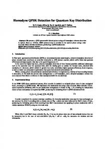
This report presents a new design that is related to an OQPSK communication system. The following description is presented to enable any person skilled in the art to make and use this new design. Various modifications to the preferred embodiment will be readily apparent to those skilled in the prior art. This design is intended to be used for any communication systems which utilize OQPSK modulation. A block diagram of a conventional OQPSK modulator/ demodulator is illustrated in Figure 1. The NRZ (Non-Return-toZero) data stream DT entering the modulator is converted by encoding and serial-to-parallel converter 1 into two separate data trains IT and QT. IT is the in-phase data stream, and the other is quadrature-phase QT, with the symbol rate Rs equal to half that of the incoming bit rate Rb. For the OQPSK modulation system discussed here, the QT data stream is offset with respect to the IT data by delaying it by an amount equal to the incoming signal bit duration Tb. Thus, if Ts is the symbol duration, then the delay is (Ts/2). The relationship between the IT and QT data streams and the input data stream DT is shown in Figure 2. The timing of the incoming data stream is controlled by the input clock CT. The timing offset between IT and QT channels is accomplished by the delay line 2 . Both IT and QT data streams are separately applied to multipliers 3 and 6 , respectively. The second input to the multiplier 3 is the carrier signal cos(oCt), and the second input to the multiplier 6 is the carrier signal shifted by exactly 90° (i.e. sin(wct)). The output of each multiplier is a biphase PSK signal. The output of multiplier 3 has phase Oo or 180° relative to the carrier phase, depending on whether IT = 0 or IT = 1 (also symbolized respectively by -IT or IT). The output carrier from multiplier 6 will have the phase of either 90° or 270° relative to the carrier phase, depending on whether QT = 0 or QT = 1 (also symbolized respectively by -QT or QT) The output multipliers are then summed in a linear adding means 7 to give an OQPSK signal. This signal is then transmitted via any suitable transmission medium to a receiver. The noise introduced in the medium is illustrated by a linear adding means 8a. At the receiver, the demodulator performs the inverse operation of the modulator and generates the output data stream DR = DT.
.
For coherent OQPSK systems, a coherent carrier must be recovered from the received signal, and a coherent clock must be reconstructed from the demodulated data waveform. A conventional OQPSK demodulator is shown in Figure 1, and includes balanced 3
demodulators 10 and 13, carrier recovery circuit 11, clock recovery circuit 16, low-pass filters 14 and 15, detectors 17 and 18 for bit streams recovery, delay line 19, and decoder and parallel-to-serial convertor 20. The received data stream DR is not always equal to the transmitted data stream DT because of noise and phase ambiguities in the phase of the recovered carrier. If the carrier recovery circuit can lock on the reference phase of the received carrier, then IR =: IT, QR =: QT, and hence DR = DT. However, for the received data without phase rotation direction ambiguity, the received carrier has four possible phases relative to the reference carrier phase; the receiver can lock on any of the four phases. For received data with phase rotation direction ambiguity, again, there are four additional possible phases relative to the reference carrier, and the receiver can lock on any of the eight phases associated with it. The effect of an incorrect recovered-carrier phase on the demodulated data is shown in Table 1. TABLE 1. THE RELATIONSHIPS BETWEEN THE TRANSMITTED AND RECEIVED DATA FOR THE OQPSK SYSTEM DESCRIBED IN FIGURE 1 CARRIER PHASE ERROR (DEGREE)
0
90
RECEIVED DATA WITHOUT PHASE ROTATION DIRECTION AMBIGUITY (NORMAL SENSE) IR QR IT
'QT
RECEIVED DATA WITH PHASE ROTATION DIRECTION AMBIGUITY (REVERSE SENSE) IR QR
QT
QT
IT
IT
IT
-QT
180
-IT
-QT
-QT
270
QT
-IT
-IT
'IT QT
NOTE: The negative sign indicates the complement of the data. From this table, it can be seen that for each case (normal or reverse sense) the locked-in phase may be any one of four possible phases. Thus, the resolution of the eight possible relationships between the transmitted and the received phase(s) is a formidable problem in OQPSK systems. Furthermore, this 4
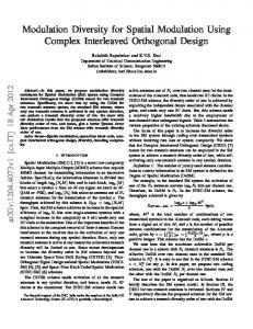
table reveals that for received data without phase rotation direction ambiguity, a Type 3 error occurs when the carrier phase error is either at 90° or at 270°. For received data with phase rotation direction ambiguity, a Type 3 error occurs when the carrier phase is either at Oo or at 180°. As described earlier, these eight unique combinations uniquely define the phase ambiguities, which are combinations of the three specific types of errors mentioned above, namely Type 1, Type 2, and Type 3 . The classification of the phase ambiguities into three definable errors allows the concepts of (1) integrated carrier loop/symbol synchronizer, and ( 2 ) uniqueword detection to be applicable to an OQPSK system for resolving the phase ambiguities. Four errors can be corrected by utilizing an integrated carrier loop/symbol synchronizer using a digital Costas loop with matched arm filters. The remaining four errors are corrected by utilizing the unique-word detection technique. Generalized block diagrams of the OQPSK modulator and demodulator with phase-ambiguity correction in accordance with the teachings of the present technology are shown in Figures 3 and 4 , respectively. As illustrated in Figure 3 , the block diagram for this modulator is very similar to the conventional OQPSK modulator shown in Figure 1. The only difference is the unique code-word generators 21, 22 for generating and inserting the unique words Iy and Qu into the quadrature channels 25, 26. Each of these unique words has length N, and (Iu, Qu) is periodically clocked by CT into the data streams IT and QT, respectively. It should be mentioned here that the synchronization markers can be used as the unique code words. Through recent developments in digital technology, digital implementation of the Costas loop is becoming increasingly more attractive. Advantages of the digital Costas loop include its relative insensitivity to temperature variations and aging, and the programmability of its loop parameters (such as loop gain and loop filter time constants, Ref. 3 ) . Utilizing this technology, an integrated carrier/symbol synchronization system based on a digital decision feedback is proposed for carrier recovery loop. A new block diagram for the OQPSK demodulator is depicted in Figure 4. The new components added in this demodulator are: A/D converters 38, 39, and the phase-ambiguity resolver 4 4 . Furthermore, the carrier recovery and clock recovery loops are replaced by integrated carrier loop/symbol synchronizer 4 0 . In operation, the integrated carrier loop/symbol synchronizer 4 0 using digital Costas loop with matched arm filters will be responsible for correcting two errors due to Type 3 (for normal sense) and two other errors due to Types 1 and 2 (for reverse sense). The phase-ambiguity resolver 4 4 will correct the remaining four errors.
5
A simple example of the integrated carrier loop/symbol synchronizer loop is illustrated in Figure 5. This figure shows details of the carrier recovery loop structure. It also reveals how the carrier phase and symbol synchronization can be derived jointly. The illustrated carrier recovery loop comprises inphase accumulate and dump circuits 45a, 45b, quadrature accumulate and dump circuits 47a, 47b, hard limiters 49 and 52, delay lines 51 and 55, symbol synchronizer 50, multipliers 53 and 54, linear adder 56, and loop filter 57.
The sampled baseband signals I(n) and Q(n) (outputs of the in-phase and quadrature A/D converters 38 and 39, respectively) are routed to the in-phase and quadrature accumulators 46 and 48, respectively. It is noted here that the in-phase accumulator 46 consists of the accumulate and dump circuits 45a, 45b, and the quadrature accumulator consists of the accumulate and dump circuits 47a, 47b. The in-phase accumulator 46 is synchronized with the in-phase data stream, and the quadrature accumulator is with
the
quadrature
data
stream.
The
produces two signals, Ii(n) and Iq(n), accumulator produces Qq(n) and Qi(n). A
in-phase
accumulator
46
while the quadrature A
The estimates of symbol polarity dl(n) and d2(n) for the inphase and quadrature channels, respectively, are produced by passing Ii(n) and Qi(n) through the hard limiters 49 and 52, respectively. The in-phase estimate of the symbol polarity is used as the feedback signal to control the, timing outRut of the symbol synchronizer 50. Also, both dl(n) and d2(n) are separately applied to the in-phase and quadrature multipliers 53, 54, respectively. The second input to the in-phase multiplier 53 is the output of accumulate/dump circuit 45b, and the second input to the quadrature multiplier 54 is the output of accumulate/dump circuit 47a. The output of in-phase multiplier 53 is delayed by the delay line 55. The outputs of the delay line 55 and quadrature multiplier 54 are added by a linear adder 56 to produce tracking error signal e(n). After filtering by the loop filter 57 the error signal is fed back to the local oscillator 33 (Numerical Controlled Oscillator, NCO, see Figure 4), closing the phaselocked loop. A detailed operation of this carrier tracking loop has been described in Reference 2. It has been shown in Reference 2 that for carrier loop bandwidth (BL)-to-symbol synchronization loop bandwidth (Bs) ratio much greater than one, i.e., (BL/Bs) >> 1, this carrier tracking loop can avoid the lock points at 90° and 2 7 0 ° , hence automatic I/Q channel reversal correction. This means that the proposed carrier tracking loop can correct two errors caused by Type 3 for received data without phase rotation, and two additional errors caused by Types 1 and 2 for received data with 6
phase rotation. A ratio of BL/Bs 2 10 has proved that the loop can avoid the lock points at 90° and 270° successfully. Since the proposed carrier tracking loop can avoid 90° and 270° lock points, the relationships between the transmitted and received data for the system described in Figures 3 and 4 will be different from that shown in Table 1. For this case, the effect of an incorrect recovered-carrier phase on the demodulated data is shown in Table 2. TABLE 2. THE RELATIONSHIPS BETWEEN THE TRANSMITTED AND RECEIVED DATA FOR THE OQPSK SYSTEM WITH PHASE ROTATION DIRECTION AMBIGUITY CARRIER PHASE ERROR (DEGREE)
0
180
RECEIVED DATA WITHOUT PHASE ROTATION DIRECTION AMBIGUITY (NORMAL SENSE) IR QR IT
'IT
RECEIVED DATA WITH PHASE ROTATION DIRECTION AMBIGUITY (REVERSE SENSE) IR QR
QT
QT
-QT
-QT
IT 'IT
Translating the above relationships into the effects they create on the demodulated data in the in-phase and quadrature channels, it can be seen that there remain only three errors caused by the phase-ambiguity, and that these three errors are the three unique combinations of the three types of errors mentioned previously. The three definable errors are (1) IR = -IT, and QR = -QT; or ( 2 ) IR = QT, and QR = IT; or ( 3 ) IR = -QT, and QR = -IT. The remaining three errors can be corrected by the phaseambiguity resolver 44. A complete resolution of the phaseambiguity is accomplished by correcting these three errors. These errors are corrected by monitoring and detecting the unique words I, and QU in the quadrature channels. If -Iu and -Qu are detected in the I and Q channels, respectively, this indicates that the data in these channels are inverted. The error can be corrected by inverting the channel outputs prior to serializing the data into DR. Similarly, if -Qu and -Iu are detected in the I and Q channels, respectively, the data in both channels should be inverted and reversed. Using this concept, the block diagram of the phase-ambiguity resolver is described in Figure 6b. The illustrated phase-ambiguity resolver comprises invertors 58b, 59b, 60b, gating means 61b, 62b, 63b, parallel-to-serial converter 64b, flip-flop circuits 65b, 66b, 72, cross-coupling gate 67b, 1, correlator 69b, Qu correlator 70b, shift register 71b, and decoding matrix 68b. 7
In normal operation, the IR and QR data streams are fed through gating means 61b and 62b, respectively, to combine the data by parallel-to-serial converter 64b, to produce an output data stream DR in which an IR bit precedes the QR bit. Each of the gating means 61b and 62b is adapted to pass the data directly or after inversion, by invertors 58b and 59b, to the parallel-toserial converter. Control of gating means 61b and 62b is accomplished via the outputs of the flip-flop circuits 65b and 66b, respectively. The ouput data stream DR is also applied to the shift register 71b which has 2N stages (N is the length of the unique code word). Consider the first two combinations of Table 2 for which For these two IR = IT, QR = QT, and IR = -IT, QR = -QT. combinations, the order of the bits in the output data stream DR is correct, i.e., ITO precedes QTO by one bit, and so on. The error occurs when both of the data streams are inverted. Let time t = to be defined as the time when the shift register 71b is fully loaded with two unique words I, and Qu interlaced, as shown in Figure 6b. Because the stages of correlators 69b and 70b are connected to every other stage of shift register 71b, at time to only the Qu correlator 70b is looking at its corresponding unique word. The Qu correlator will provide either a logic output Qu on the plus (+) output line or -Qu on the minus ( - ) output line. A t time t = t-1 (one bit earlier), the I, correlator 69b will detect the 1, unique word and produce either a logic output !I on the plus (+) output line or -Iu on the negative ( - ) output line. If the correlators 69b and 70b detect 1, and Qu respectively, no action is taken. If the IR = -IT and QR = -QT, the correlators 69b and 70b will detect -Iu and -Qu, respectively, and send the representative logic signals through cross-coupling gate 67b and toggle flip-flop circuits 65b and 66b. The changes in outputs from flip-flop circuits 65b and 66b will reverse the state of the gates 61b and 62b, and pass the data streams -IR and -QR, respectively, to parallel-to-serial converter 64b. Consider the third case in Table 2 for which IR = QT, and QR = IT. For this combination, the order of the bits in the output data stream DR is not correct, and so on, QTO precedes ITO by one bit, etc. In this case, the correlators 69b and 70b will , . The decoding matrix will detect Qu followed one bit later by I generate a "reverse IR & QR" control signal. Flip-flop 72 will be toggled causing a state reversal of the gate 63b, and pass the inverted recovered-clock pulses to converter 64b. This causes a reversal of the data channels at the output of the converter 64b. Consider the last case in Table 2 for which IR = -QT, and QR = -IT. For this combination, both the data channels are inverted and then reversed. Again the correlators 69b and 70b will detect -Qu, followed one bit later by -Iu, and send the representative logic signals through cross coupling gate 67b
a
while toggling flip-flop circuits 65b and 66b. At the same time the decoding matrix will also generate a Itreverse IR & QR" control signal. Flip-flop 72 will be toggled, causing a reversal of the data channels at the output of converter 64b. The inphase and quadrature data channels must be inverted to be correct, are passing through gates 62b and 61b, respectively, rather than gates 61b and 62b, respectively, and thus the Itinvert 1~~~ control signal must toggle flip-flop 66b rather than 65b, and an "invert QRttcontrol signal must toggle flip-flop 65b rather than 66b. This is taken care of by the cross-coupling gate 67b. The switching of flip-flop 72 causes a reversal in the connections between the two input terminals and the two output terminals of the cross-coupling gate 67b. The block diagram of the decoding matrix 68b is shown in Figure 7b. The decoding matrix illustrated in this figure will be responsible for providing (1) a proper clock signal to the data decoder (if the data is encoded) and to the parallel-toserial converter, and a frame-sync signal for the subsequent data output: and (2) a reverse I & Q control signal. The embodiment comprises one-bit-delay lines 73 and 74, AND gates 75, 76, 77 and 78, OR gates 79 and 80. The logic shown in this figure is explained by the truth table shown in Table 3 . TABLE 3 . TRUTH TABLES FOR THE LOGIC SHOWN IN FIGURE 7b
REVERSE IR
O2
03
04
0
0
0
0
0
0
1
0
0
1
1
1
0
0
1
0
1
1
1
1
1
1
1
-Iu
'QuD
0
9
&
QR
TABLE 3 . TRUTH TABLES FOR THE LOGIC SHOWN I N FIGURE 7b (CONTINUED)
In order to ensure a proper lock in the input/output connections of the cross coupling gate 67b (Figure 6b), a short delay line is provided at the inputs to cross-coupling gate 67b. If the relationship between the transmit local frequency and the receive local frequency is provided, the phase rotation direction ambiguity can be avoided. Table 4 shows the relationships between the transmitted and received data for this case.
10
TABLE 4 . RELATIONSHIPS BETWEEN THE TRANSMITTED AND RECEIVED DATA FOR THE OQPSK SYSTEM WITHOUT PHASE ROTATION DIRECTION AMBIGUITY
CARRIER PHASE ERROR (DEGREE)
I
RECEIVED DATA WITHOUT PHASE ROTATION DIRECTION AMBIGUITY (NORMAL SENSE) IR QR
o 180
'IT
-QT
Based on these relationships, the phase-ambiguity correction system can be redesigned, and the block diagram for this system without phase rotation direction ambiguity is shown in Figure 6a. The illustrated phase-ambiguity correction system comprises invertors 58a, 59a, gating means 61a, 62a, parallel-to-serial converter 64a, flip-flop circuits 65a, 66a, I, correlator 69a, Qu correlator 70a, shift register 71a, and sync generator 68a. Since there are only two combinations (hence only one error), the operation of this phase-ambiguity resolver is very simple. In normal operation, the IR and QR data streams are fed through gating means 61a and 62a, respectively, to combine the data by parallel-to-serial converter 64a, to produce an output data stream DR in which IR bit precedes the QR bit. Each of the gating means 61a and 62a is adapted to pass the data directly or after inversion by invertors 58a and 59a, to the parallel-toserial converter. Control of gating means 61a and 62a is accomplished via the outputs of the flip-flop circuits 65a and 66a, respectively. The output data stream DR is also applied to the shift register 71a which has 2N stages (N is the length of the unique codeword). Consider the (only) error shown in the second combination of Table 4 for which IR = -IT, and QR = -QT. For this combination, the order of the bits in the output data stream DR is correct, i.e., ITO precedes QTO by one bit, and so on. The error occurs when both of the data streams are inverted. Let time t = to be defined as the time when the shift register 71a is fully loaded with two unique words, 1, and Qu, interlaced as shown in Figure 6a. Because the stages of correlators 69a and 70a are connected to every other stage of shift register 71a, at time to only the Qu correlator 70a is looking at its corresponding unique word.
11
The Qu correlator will provide either a logic output Qu on the plus (+) output line or -Qu on the minus ( - ) output line. At time t = t-1 (one bit earlier), the 1, correlator 69a will detect the I, unique word and produce either a logic output Iu. on the plus (+) output line or -Iu on the negative ( - ) output line. If the correlators 69a and 70a detect 1, and QUI respectively, no action is taken. If IR = -IT, and QR = -QT, the correlators 69a and 70a will detect -Iu and -Qu, respectively, and send the representative logic signals to toggle flip-flop circuits 65a and 66a. The changes in outputs from flip-flop circuits 65a and 66a will reverse the state of the gates 61a and 62a, and pass the data streams -IR and -QR, respectively, to parallel-to-serial converter 64a. A simple example of the sync generator 68a is illustrated in Figure 7a. The embodiment comprises AND gates 75a, 76a, and OR gate 79a. The logic is self-explanatory.
12
111. SUMMARY A new technique for resolving the phase-ambiguity in OQPSK communications systems using the digital Costas loop with integrated symbol synchronizer, and the unique-word (or syncmarker) detection method is presented. The purposes of the design presented in this report are (1) to enhance the performance of the carrier recovery subsystem, (2) to minimize the complexity of an OQPSK receiver by removing the redundant circuits from the previous design, and (3) to eliminate the timing dependent on the parallel-to-serial conversion clock.
In accordance with the present technique described in the previous sections, an OQPSK digital Costas loop with integrated symbol synchronization and a unique-word (or sync-marker) detector are provided for digital communications systems that utilize OQPSK modulation. It has been discovered that there are eight possible combinations of the three possible errors, Type 1, Type 2, and There are four possible Type 3 error, mentioned above. combinations of errors associated with Type 1 and Type 2 error. The remaining four combinations are with the Type 3 error. The technique proposed here will not identify the phase error of the recovered coherent carrier that caused the errors, but correct the errors caused by the phase ambiguities. In the preferred embodiment, the OQPSK receiver is implemented by an integrated carrier loop/symbol synchronizer using a digital Costas loop with matched arm filters, and a unique-word detector. The use of digital Costas loop allows the novel communication techniques to be implemented in the programmable digital processor while the loop gain and loop filter time constants are programmable. The integrated carrier loop/symbol synchronizer is properly designed such
that
two
of
the
errors
caused
by
Type
3
( I / Q channel
reversal due t o the phase ambiguities) can be corrected in the carrier tracking loop. For OQPSK systems with phase rotation direction ambiguity, the use of this loop can correct two additional errors caused by Type 1 and 2. Hence, four errors can be corrected by using this carrier tracking loop. The remaining errors are corrected by using the unique-word detector. Since only four possible combinations of errors remain, the uniqueword detector can be designed with a very simple circuitry using invertors, AND gates, OR gates, and the like.
13
IV. CONCLUSIONS AND RECOMMENDATION
Based on the above description, the following conclusions can be reached: The eight possible ambiguous phase conditions associated with (a) the digital Costas loop with integrated symbol synchronization, .and (b) the uniqueword detection technique. 1.
OQPSK systems can be resolved by using
2. The use of digital Costas loop with integrated symbol synchronization for the carrier tracking loop will resolve four possible ambiguous phase conditions caused by the recovered carrier being at the wrong phase(s). 3. The use of the unique-word detection technique will resolve the remaining four ambiguous phase conditions.
4. The use of the OQPSK digital Costas loop with integrated symbol synchronization for the carrier recovery loop will (a) improve the carrier tracking performance at low signal-to-noise ratio (Ref. 2); (b) make the carrier tracking loop less sensitive to temperature variations and aging; and (c) allow loop parameters (such as loop gain and loop filter time constants) to be programmable (Ref. 3 ) . 5. A s compared to the prior claims in Reference 4, the complexity of the phase-ambiguity resolver described here is reduced by half.
6. A s compared to the previous design described in Reference 5 the phase-ambiguity resolution technique described here eliminates the timing dependent on the parallel-to-serial conversion clock.
Since the proposed technique has many advantages as compared to the previous techniques, it is recommended that the CCSDS adopt this technique as a standard method for the phaseambiguity resolution for future OQPSK communications systems.
14
V. REFERENCES [l] Tien Manh Nguyen, Phase-Ambiguity Resolution For QPSK Modulation, Part I: A Review, JPL Publication 89-004, CCSDS Report No. 6-73, February 20, 1989, Jet Propulsion Laboratory, California Institute of Technology.
[2] Bruce F. Mcguffin, Paulman Kwong,"I/Q Reversal Correcting Properties of an SQPSK Costas Loop With Integrated Symbol Synchronization,Il IEEE Transactions on Communications, Vol. 36, No. 9, September 1988. [3] Marvin K . Simon, Kai T. Woo,*@AliasLock Behavior of SampledData Costas Loop, "IEEE Transactions on Communications, Vol. com-28, No. 8, August 1980. [4] C. J. Wolejsza, E. R. Cacciamani, Phase-Ambiguity Resolution in a Four-Phase PSK Communications System, U.S. Patent No.3736507, May 29, 1973. [5] E. R. Cacciamani, C. J. Wolejsza,lIPhase-Ambiguity Resolution in a Four-Phase PSK Communications System,lgIEEETransactions on Communication Technology, Vol. COM-19, NO. 6, December 1971. [6] Y. Tsuji,@@Phase Ambiguity Resolution in a 4-Phase PSK Forward-Error-Correcting Modulation System with Convolutional Codes, "Cornsat Technical Review, Vol. 6 No. 2, Fall 1976.
15
\
M
16
I-
I-
W
W
zI-
2 I-
I-n b
b
m
I-
I-n (D
-I
R
(D
n
I-
u)
I
I--
I-n
cy
*
*
I--
M
n
-
n
n cy cy
n
I-
1
nI-
0
m
w
I-
I-"
1I
X
I3
-
-
0
17
IW
u)
LL LL
I-
I-
i 0
b
6
W
io
I
CJ
z
0
H
3 I
I
F
0
w
0
n
% H
a N
z
3 X
I3
H
8
z
c
0 0 N
p: 0 Er
a
I
c
N
I
I
N
w cd 5
u
H
Er
18
c
a
ooe
t
. n
..
19
6
P 0
I-
-1 I
ffi
!3
w
c
n
"Y
I I I I I I I I I I I I I
1
I
I
::
m
-I
W
I I - _I
20
ffi 3
uH Er
I
I I
I I I I I I I I I I I I I I I I I I I I I I I I I I
$1 a
21
I I 1 I I I I
I I
t r
I ,
I I I I I I I I I
I I I I I I I I
I I I I I
L-.
21
I
I I
I I I I I I I I
3
pl :I :I 21
I I I I I
I I I
I
I I I I
I I I I I I I I I I
I I I I I
f I
1
I I I I 1 I I I
I
r
I I I
22
I I I I I I I I I
I
I I I I I I I I I I I I I
I I I I I I I I I I I
I I I I
L
_I
23
w m a K O w a > a wK
r
I
I I I I I I I
I I I I I I I I I I I I I I I I I I I I I I I I
I
:I
I I
t
4 0
51
El :I
I I I I I I I I I
La
0
24
TECHNICAL REPORT STANDARD TITLE PAGE ~~
~~
1. Report No.
~~
2.
Government Accession
No.
3. Recipient's Catalog No.
89-4, Part I1
4. Title and Subtitle
PHASE-AMBIGUITY RESOLUTION FOR QPSK PART 11: A METHOD TO RESOLVE OFFSET QPSK
5. Report Date
May 15, 1989
6. Performing Organization Code 8. Performing Organization Report No
7. Author($)
Tien M. Nauven IO. Work Unit No.
9 . Performing Organization Name and Address
JET PROPULSION LABORATORY California Institute of Technology 4800 Oak Grove Drive Pasadena, California 91109
11. Contract or Grant No.
NAS7-918 (13. Type of Report and Period Covered
JPL Publication
12. Sponsoring Agency Name and Address
NATIONAL AERONAUTICS AND SPACE ADMINISTRATION 20546
Washington, D.C.
14. Sponsoring Agency Code
RE211 BG-314-40-22-70-08
15. Supplementary Notes
16. Abstract
Part I1 of this report presents a new method to resolve the phase-ambiguity for Offset QPSK modulation systems. Whenanoffset Quaternary Phase-Shift-Keyed (OQPSK) communications link is utilized, the phase ambiguity of the reference carrier must be resolved. At the transmitter, two different unique words are separately modulated onto the quadrature carriers. At the receiver, the recovered carrier may have one of four possible phases, 00, 900, 180°, or 2700, referenced to the nominally correct phase. The IF portion of the channel may cause a phase-sense reversal, i.e., a reversal in the direction of phase rotation for a specified bit pattern. Hence, eight possible phase relationships (the so-called eight ambiguous phase conditions) between input and output of the demodulator must be resolved. Using the In-phase (I)/Quadratu (Q) channel reversal correcting property of an OQPSK Costas loop with integrated symbol synchronization, four ambiguous phase conditions are eliminated. Thus , only four possible ambiguous phase conditions remain. The errors caused by the,remaining' ambiguous phase conditions can be correctedbymonitoring and detecting the polarity of the two unique words. The correction of the unique word polarities results in the complete phase-ambiguity resolution for the OQPSK system.
I 18.
7. Key Words (Selected by Author($))
Spacecraft Communications, Command, and Tracking: Communications
9 . Security Clesif. (of this report)
UNCLASSIFIED
Distribution Statement
Unclassified--Unlimited
20. Security Classif. (of this page) UNCLASSIFIED
21. No. of Pages
30
22. Price