I. INTRODUCTION
Phase Modulated DGPS Transmitter Implemented with a Clamped-Mode Resonant Converter ´ SERGIO A. GONZALEZ ´ VALLA, Senior Member, IEEE MARÍA INES CARLOS H. MURAVCHIK, Senior Member, IEEE UNLP Argentina
A clamped-mode resonant converter (CMRC) is proposed to be used as a transmitter which broadcasts correction signals in a differential Global Positioning System (DGPS). The digital information of the DGPS modulates the carrier with different modulation methods minimum shift keying (MSK) (recommended for the marine radiobeacon band), stepped binary phase shift keying (S-BPSK) and BPSK. The first two methods allow keeping the converter’s operation in soft switching mode. Extensive trials under impedance mismatch and modulation conditions confirm that the soft switching mode is preserved.
Manuscript received March 20, 2003; revised December 8, 2003 and March 1, 2004; released for publication March 30, 2004. IEEE Log No. T-AES/40/3/835888. Refereeing of this contribution was handled by W. M. Polivka. This work was supported by National University of La Plata (UNLP), Agency for the Promotion of Science and Technology (ANPCYT), National Research Council (CONICET), and Buenos Aires Province Research Council (CICPBA). Authors’ address: Laboratory of Industrial Electronics, Control and Instrumentation (LEICI), Electrical Engineering Dept., UNLP, CC 91, 1900 La Plata, Argentina, E-mail: (
[email protected]). M. I. Valla and S. A. Gonza´ lez are also with CONICET. C. H. Muravchik is also with CICPBA. c 2004 IEEE 0018-9251/04/$17.00 °
The differential Global Positioning System (DGPS) concept was created to improve the position estimates for several civil applications (land transportation, precision agriculture, maritime traffic, civil aviation, etc.). In DGPS, Earth stations whose positions are accurately known measure the difference between their actual positions and the GPS measurements. With this information they generate and transmit a correction signal to a GPS receiver in an unknown location (within radii of a few hundreds of kilometers to keep correlated GPS errors). This system is also employed in several countries to enhance maritime safety. In particular, U.S. Coast Guard (USCG) provides the transmission of the differential correction signal in the radiobeacon band (285 kHz—325 kHz). This service operates from about 50 remote broadcast sites [1—4]. A DGPS-radiobeacon broadcast network is attractive since it does not interfere with the marine and aviation direction finders. The radiobeacon band is available at low cost and it propagates in ground wave mode, so it reaches distances which are well beyond the radio horizon. It is also very attractive for applications other than navigation, like precise surveying and geological studies. Different kinds of RF power amplifiers can be employed to broadcast the correction signal from the known location (Earth station) to the unknown location (GPS receiver) in the radiobeacon band. The power amplifier is required to have low energy consumption and harmonic distortion. To reach an efficiency higher than 80%, it is necessary to use tuned power amplifiers class D, E, F [6—9]. The main characteristics of the resonant amplifiers are as follows. 1) They require a high quality factor (Q), in order to obtain a sinusoidal voltage on the load from a square wave with a given mean value at the input of the amplifier. In resonance, the peak voltage on the elements of the resonant network is Q times the source voltage. 2) In low frequency amplifiers the required reactive components are large and heavy, increasing the power loss involved in this components. 3) Optimal design of the resonant amplifiers does not tolerate load variations. With impedance mismatch, high voltage or high current on the power switches appear. One way to improve the design of the amplifier is to obtain a voltage with low harmonic distortion at the input of the resonant circuit. In this way it is possible to use a low-pass filter to minimize the remaining harmonics. The design of a voltage clamped-mode resonant converter (CMRC) [13—15] as an RF power amplifier is proposed here. This amplifier is built with a bridge power converter which generates a zero mean value voltage at the input of a low pass filter. Besides controlling the “clamped voltage” to zero during a convenient time interval, it can also eliminate or
IEEE TRANSACTIONS ON AEROSPACE AND ELECTRONIC SYSTEMS VOL. 40, NO. 3
JULY 2004
919
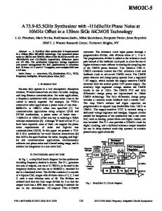
minimize the lower harmonics such as the third one. This power amplifier presents high efficiency even under high load variations, low distortion, and low stress on the power switches. The DGPS correction information can be phase modulated directly on the switches of the RF power amplifier. Minimum shift keying (MSK) is used in services of DGPS in the radiobeacon band [5]. The power amplifier is designed so that the switches of the CMRC commutate in a soft switching mode. This condition is maintained even during the changes of binary symbols that modulate the carrier. It is easy to modulate the phase of the CMRC, only by delaying the switches driving signals. The stepped binary phase modulation scheme (S-BPSK) is a binary phase modulation with a smooth phase transition between adjacent bits. The design with S-BPSK modulation shown here allows maintaining the power amplifier operation in a soft switching mode. As a result, the number of high power semiconductors components needed for the amplifier is reduced. MSK can be seen as a limiting case of the S-BPSK. The soft switching mode is also achived for the MSK used in DGPS. The paper is organized as follows. In Section II the CMRC is presented. In Section III the power amplifier is designed. Section IV presents the modulation of the CMRC. In Section V experimental results are shown. Section VI concludes the paper. II. VOLTAGE-CLAMPED CONVERTERS The RF switched power amplifiers such as classes D, E, DE, F, obtain the carrier by switching at the frequency of the series or parallel resonant frequency of the load network. This network should have a high quality factor in order to get low harmonic content [6, 7, 8]. In LF and VLF applications the required output power is high and this imposes severe limitations in the design of the resonant circuit due to the high stresses on the reactive elements and the power switches. One way to lower these stresses is to use a less selective filter with lower Q. Thus, it is important to generate a voltage waveform with lower harmonics at the input of the resonant network. The voltage-clamped resonant converter (CMRC) is basically a full-bridge class D amplifier which allows to fulfill the previous goal. Fig. 1(a) shows the CMRC together with a T low-pass filter and the load (an antenna and this coupling transmission line). Each column switches at a fixed frequency with a 50% duty cycle. The phase shift between both columns (' = !S t' ) determines the pulsewidth of the output voltage vab , as shown in Fig. 1(b). It is possible to obtain an output voltage with no dc and third-order harmonic, by controlling the pulsewidth to a value close to 120± . Then a third-order low-pass filter provides sufficient attenuation of the remaining harmonics. Moreover, since the pulsewidth is 920
Fig. 1. (a) Power amplifier. (b) Voltage and current output of CMRC and driving signals.
controlled with no modification of the duty cycle of the power switches, the control of the power gain of the amplifier is obtained at constant frequency. The CMRC, being a full-bridge converter allows full use of the amplitude of the power supply which is directly applied to the filter. When compared with a class D half-bridge amplifier the CMRC allows a decrease of the current on the power switches, beyond the division between the two columns. In the HF range, the power efficiency of class D amplifiers goes down mainly due to switching losses which are proportional to the switching frequency. In order to improve efficiency, the resonant amplifier is designed absorbing the parasitic capacitance of the power switches [7, 9—11]. For frequencies in the range of LF and VLF the parasitic effects are not significant to the output waveform of the RF amplifier. Nevertheless, the switching and conduction losses may be decreased shifting the switching frequency slightly above the resonance frequency of the load network. In the CMRC it is possible to slightly shift the switching frequency with respect to the cut-off frequency of the filter, without practically introducing changes in the harmonic distortion of the carrier. A correct selection of the switching frequency
IEEE TRANSACTIONS ON AEROSPACE AND ELECTRONIC SYSTEMS VOL. 40, NO. 3
JULY 2004
allows the power devices to turn-on as zero voltage switches (ZVS). The output current of the power amplifier iL is shown in Fig. 1(b), indicating which device is conducting in every time interval. It may be seen that each of the four power switches are ZVS, because the switches begin to take current through their own diodes. It is important to meet ZVS condition because in this way there is no need for high speed free-wheeling diodes. Indeed, it suffices to use the built-in diodes of the power metal-oxide semiconductor field-effect transistor (MOSFETs), reducing the number of required power devices. The switching losses are minimized through soft turn-on of the MOSFETs. The conduction losses are also reduced since the diodes in series with MOSFETs (required when external diodes are used for freewheeling) are no longer needed. The reduced power components number also allows improving the implementation with regards to electromagnetic interference (EMI) control, cost, and reliability. Moreover, operation as ZVS allows to implement a quite large dead time in the switching excitation preventing the short circuit of each column with no effect on the output waveform.
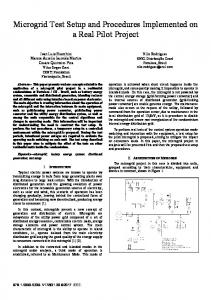
Fig. 2. The “T” filter and its parallel equivalent circuit.
In order to switch all the MOSFETs as ZVS, the switching frequency should be above the cut-off frequency of the resonant circuit, and the duty cycle of the voltage vab should be larger than a certain limit which depends on the load conditions. In [12], this operation mode is denoted as mode A and any other way of operation is denoted mode B. The boundary between modes A and B depends on the duty cycle D (= !S t± =¼), the cut-off frequency, the quality factor, the characteristic impedance of the filter and the switching frequency of the amplifier. The details of these operating modes are avoided since they are not essential to the discussion in this paper.
attenuates the components of undesired frequencies and it also matches the impedances between the CMRC and the load. The antenna impedance may depart from its nominal value. It changes from inductive above the resonance frequency to capacitive below that frequency. On the other hand, the impedance presented by the transmission line used in the connection, varies depending on the line length. So there is some impedance mismatch between the output filter and the load. The design of the CMRC with a T filter must guarantee operation in mode A, avoiding changes to mode B operation even when impedance mismatches occur. If mode B operation arose the power devices might exceed their safe power rates. The plots in [12] may be utilized to set the boundary between mode A and mode B operation. To use this tool for designing the T filter, a series or parallel equivalent circuits must be obtained. This circuit is only an approximation to the T filter when a neighborhood of the switching frequency is considered. The T filter here is of third order and can be immediately reduced to a low-pass second order one which is similar to the parallel load case in [12]. In the present case, the design of the power amplifier will be made with a switching frequency of 300 kHz and for an output power of 300 W. This frequency, corresponds to the center of the radiobeacon band. The carrier is obtained by filtering the voltage vab with a Butterworth low-pass filter of three elements, with nominal load R0 = 50 −.
III. POWER AMPLIFIER DESIGN
A. Filter Design
The optimal design of tuned amplifiers implies switching of the power MOSFETs with the minimum power loss and this occurs for a certain nominal load [7, 10, 11]. Any change or mismatch of the load moves the operating point away from the optimum, compromising the resonant operation. Complex control circuits are required to guarantee the optimal functioning. The CMRC presents the advantage that it can operate in a quasi optimum situation even under a broad range of load variations. It only needs a proper design of the low-pass filter in order to guarantee the ZVS operation of the four switches with no change in the voltage pulsewidth. The design of the RF power amplifier with a CMRC relies on the low-pass filter. The filter
Fig. 2 shows the actual filter and its parallel equivalent circuit. It is obtained equating the impedance of both circuits in the figure for the p nominal load condition R0 = Z0 = L=C = 50 − at the frequency s 1 l1 + l2 !0 = p LC c1 l1 l2
A. Operating Modes A and B
´ GONZALEZ ET AL.: PHASE MODULATED DGPS TRANSMITTER
where the l1 , l2 , c1 are the coefficients indicated in Fig. 2 which characterized the type of filter (Butterworth, Chebychev, etc.). The equivalent circuit is valid only over a narrow frequency range, so it is important to fix the switching frequency !s within this range. Then, the parameters 921
Fig. 3. “T” filter with a load ZL .
C and L of the T filter are expressed by C = QPe L=
!n 1 !s R0 fc1 [1 + (!f l2 )2 ] ¡ l2 g
!n R0 [1 + (!f l2 )2 ] !s l1 QPe
(1)
(2)
p where !f = l1 + l2 =c1 l1 l2 , !n = !s =!ce , !ce = p 1= l1 L(c1 C + Ce ) is the equivalent cut-off frequency of the equivalent circuits, and QPe is the quality factor of the equivalent circuits, given by v " u µ ¶2 # u c1 l t 2 QPe = [1 + (!f l2 ) ] : (3) + 2 l1 l1 For a desired Butterworth filter, the coefficients l1 , l2 , and c1 are obtained and the equivalent quality factor is calculated by means of (3). Using the plot of Qp as a function of !n given in [12], the calculated value of QPe is entered and a !n value is chosen for the amplifier to work in mode A. Finally, L and C are obtained from (1) and (2). The design takes into account the mismatch between the antenna impedance and the transmission line, considering that the actual load may depart from its nominal design value as shown in Fig. 3. This is specified by a standing wave ratio (SWR) equal to or less than 2. Actually, the load will remain inside a circular region of the impedance plane [12]. This load variation affects the natural frequency of the resonant circuit since the inductance at the output of the filter is modified by the reactive part of the load. The reactance of the load is defined as, XL = !s LL ,
XL > 0
XL = ¡1=!s CL = !s (¡LL ),
XL < 0:
Then, a new inductance is defined at the output of the filter, L02 = l2 L + XL =!s : For a third-order Butterworth T filter the l2 = 1=2, c1 = coefficients of the filter p are l1 = 3=2,p 4=3 that lead to !f = 2 and Qpe = 3=2. A value of !n should be chosen to determine those of L and C. There exists a trade-off between the requirement to operate in mode A and p the attenuation of the filter. Fixing !S = !C = 1= LC, the filter gain at the switching frequency is equal to ¡3 dB, which is a reasonable attenuation, and it is the minimum value of 922
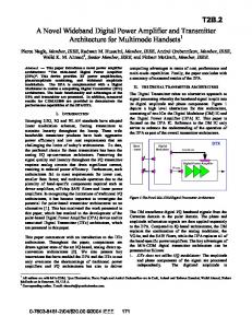
Fig. 4. Operation area for parallel equivalent circuit with SWR = 2.
!n that satisfies operating in mode A. The normalized frequency is obtained from µ ¶2 [1 + (!f l2 )2 ] !n 1 1 LC = 2 = : (4) !c !s l1 fc1 [1 + (!f l2 )2 ] ¡ l2 g p Since !s = !c , the value of !n is given by, !n = l1 = 1:2 and the values of L and C are found to be L = 26 ¹H and C = 10:4 nF. Fig. 4 depicts the quality factor as a function of !n , for a parallel equivalent circuit and D = 2=3. It shows the operating region for the variable load (SWR · 2) and the filter designed in this section. The nominal load is characterized by a single point labeled RL = 50 −, XL = 0. The line drawn inside the operating region represents the operation of a purely resistive load. The points above this line correspond to an inductive load, while those below the line represent a capacitive load. It is seen that a highly reactive load pushes the operating point towards the boundary between modes A and B. B. Experimental Results Fig. 5 shows the experimental set-up. The power amplifier is fed directly from the mains through a diode bridge rectifier with a capacitor filter. A high frequency transformer provides electrical isolation as well as voltage level transformation. It has been designed using transmission line techniques, to guarantee a broad bandwidth [16]. The power inverter was implemented with IRF720 power MOSFETs. With the values of L and C of the previous section, the output filter was implemented with a capacitance of 13 nF, an input inductor of 39:4 ¹H and an output inductor of 12:9 ¹H. Fig. 6 and Fig. 7 illustrate some experimental results. Those corresponding to the nominal load are shown in Fig. 6. The output voltage and current of the inverter are shown in Fig. 6(a). It can be seen that
IEEE TRANSACTIONS ON AEROSPACE AND ELECTRONIC SYSTEMS VOL. 40, NO. 3
JULY 2004
Fig. 5. Power amplifier set-up.
when the voltage pulse is applied, the current is taken by the corresponding diode and the MOSFETs are turned-on as ZVS. This proves that the amplifier is operating well inside mode A, as predicted by the design. The voltage at the filter output is shown in Fig. 6(b). This waveform of 122 V rms is applied to the antenna and the power delivered is 289 W, very close to the design value. The full bridge has an efficiency of 97%, and the filter and transformer efficiency is 95%. The overall efficiency is 92%. The output voltage spectrum is shown in Fig. 6(c) where the fundamental component at 300 kHz along with some odd harmonics can be seen. Note that the 5th and 7th harmonics are ¡45 db and ¡55 db below the fundamental component, respectively; while the 3rd harmonic at ¡50 db and its multiples are not exactly canceled. The total harmonic distortion (THD) is 0.67%. Fig. 7 shows the most critical case of mismatch that pushes the amplifier to operate very close to the boundary between the mode A and B. The zero crossing of the current occurs immediately after the application of the voltage pulse. This situation corresponds to a load impedance equal to RL = 35:3 − and XL = 23:64 −. IV. CARRIER MODULATION IN THE CMRC The standard modulation method for DGPS in the radiobeacon band is MSK. This is a special case of the continuous phase frequency shift keying (CPFSK). Its continuous phase feature reduce the harmonic content increasing the amplifier spectral efficiency. The phase or frequency modulated carrier wave may be expressed as v(t) = A sin(2¼fC t + µ(t))
(5)
where the amplitude A and the carrier frequency fc are constant. For the case of MSK the phase µ(t) should be, Z µ(t) = 2¼
¢f dt
(6)
´ GONZALEZ ET AL.: PHASE MODULATED DGPS TRANSMITTER
Fig. 6. Nominal load RL = 50 −. (a) Voltage and current supplied by the inverter (100 V/div, 1 A/div, 500 ns/div). (b) Load voltage (50 V/div). (c) Carrier spectrum (20 dB/div 500 kHz/div).
where ¢f = 1=(4Tb ) and Tb is the inverse of the transmission bit rate. In this way the transmission frequency for one binary symbol is f1 = fC ¡ ¢f, while for the other binary symbol it is f2 = fC + ¢f. When using MSK the carrier phase varies linearly with time so that after a bit time Tb , the total phase shift equals ¼=2 rad in advance or delay with 923
Fig. 7. Voltage and current at filter input with inductive load RL = 35:3 −, XL = 23:64 −. (80 V/div, 1 A/div, 500 ns/div).
respect to the carrier depending on the transmitted symbol. In the previous section it was shown that the power amplifier operates in mode A even with load mismatches but with an unmodulated carrier. Now it
is important to analyze how to introduce the binary information to modulate the carrier wave. From the amplifiers view point it is important to see the modulation as a delay introduced in the driving signals of he power switches and this is not easily seen when using MSK. In this section we try to show the feasibility of using MSK preserving the mode A operation of the power amplifier. The most stringent condition on the CMRC is imposed by a binary phase shift keying (BPSK) modulation. Indeed, when the binary information changes from one symbol to the next, BPSK forces a phase shift of ¼ rad in only one cycle of the carrier. This means that BPSK introduces a time delay equal to 1=(4fC ) on the driving signals of the power switches of the CMRC or equivalently, to a half period delay on E1 and E2 (Fig. 1). The 180± phase delay increases the pulsewidth of the voltage vab generating a transient behavior on the currents of the power switches. This current transient, depending on the load characteristics, may force the CMRC out
Fig. 8. Simulation voltage and current output waveforms of CMRC with BPSK modulation and for different loads. Voltage (scale 1 : 1), current (scale 50 : 1). (a) RL = 25 −. (b) RL = 50 −, XL = 35:35 −. (c) RL = 75 −, XL = 35:35 −. (d) RL = 100 −. 924
IEEE TRANSACTIONS ON AEROSPACE AND ELECTRONIC SYSTEMS VOL. 40, NO. 3
JULY 2004
Fig. 9. S-BPSK modulation.
Fig. 10. Linear profile of phase.
of mode A operation. Fig. 8 shows the voltage vab with a cycle 1.5 larger than the corresponding carrier cycle and the current for several load conditions. All these conditions correspond to an SWR · 2. Only in the case of a purely resistive load (RL = 25 −) the switches continue to operate as ZVS. In the other cases the CMRC operates in mode B with the risk of exceeding the switches rates. This is mainly due to the decrease of the instantaneous frequency to a value near (2=3)fC . A decrease in the switching frequency with respect to the cut-off frequency of the equivalent filter may be seen as a shift to the left of the operating region for the variable load in the plots of Qp (Fig. 4). In this way the operating point enters in the region of mode B operation [12]. The transmission rate is in the order of 50 to 200 bits/s, much smaller than the carrier frequency. So there are many carrier cycles between two consecutive data transitions. This means that it is possible to introduce a gradual modulation to avoid leaving mode A operation. Then, the required 180± phase shift is implemented with several smaller phase shifts distributed among several carrier cycles. This modulation method is denominated in the following as stepped binary phase modulation (S-BPSK).
be smaller than the case of BPSK. This frequency shift decreases by increasing the number of cycles employed to obtain the complete phase shift. With this line of reasoning, MSK may be seen as special case of S-BPSK in which the time employed to make the phase shift equals to the time of a bit. This means that MSK employs the largest possible time and the minimum phase shift on each cycle. So if the CMRC is capable to operate in mode A with a S-BPSK distributed into 15 cycles, then it will remain in mode A when modulated with MSK. It is evident that S-BPSK forces more severe conditions on the CMRC opration than MSK.
A. CMRC with S-BPSK Modulation S-BPSK on the CMRC is made distributing the total delay (Tc =2) on the driving signals in several carrier cycles. Fig. 9 depicts with solid line the driving signals E1 and E2 and the resulting voltage vab when a change of symbol occurs. The dashed lines show the signals with zero phase shift. It should be noted that the modulation process begins at t = ¿1 . From this time, successive tr delays during n cycles are introduced in the driving signals. After 2n half-cycles the modulation process finishes. The final phase voltage vab is ¼ rad out of the phase with respect to the original wave form. Adopting n = 15 for the transition from one symbol to another, a 6± phase shift is introduced in each half-cycle. Fig. 10 shows the phase changes in the carrier as a function of the number of cycles. Each phase change corresponds to the time 2tr generating a “linear” profile. The frequency shift from the nominal value during linear phase modulation is determined by the time employed to make the ¼ rad phase shift. It will always ´ GONZALEZ ET AL.: PHASE MODULATED DGPS TRANSMITTER
V.
EXPERIMENTAL RESULTS OF S-BPSK
The binary signal directly drives the power amplifier shown in Fig. 5. Experimental results obtained with phase modulated CMRC are shown in Fig. 11 and Fig. 12. This test was performed with nominal load. In Fig. 11 the filter output signal of the CMRC is depicted. It shows the use S-BPSK with 15 carrier cycles to make the transition from one symbol to the next. This is equivalent to shifting the phase of the carrier 12 deg per cycle. It also shows that after 15 cycles, the carrier changed its phase in ¼ rad. Fig. 12 depicts the pulsewidth of the voltage vab and the output current of the inverter when the modulation process starts. It shows that the MOSFETs are turned-on as ZVS and that the pulsewidth increases 38 ns from the carrier pulsewidth 1:1 ¹s. During the time interval in which the carrier phase changes, the carrier frequency decreases 9.6 kHz approximately, due to the number of cycles adopted for the transitions. VI. CONCLUSIONS A voltage-clamped mode voltage resonant converter was employed in the implementation of a DGPS transmitter. Based on design tools previously developed by the authors, the converter and the output filter were designed, guaranteeing that the four MOSFETs of the power amplifier turn-on with zero voltage. The proposed design improves the efficiency of the transmitters through soft turn-on of the power switches and reduces the number of power components. The experimental set-up had 925
Fig. 11. Modulated carrier wave (50 V/div, 10 ¹s/div).
Fig. 12. Voltage and current waveforms at output of CMRC when modulation starts (50 V/div, 1 A/div, 1 ¹s/div).
overall efficiency of 92%. In addition, this design provides safe operation under load variations in a controlled and predictable neighborhood of the operation point. The CMRC allows to easily modulate the carrier phase by direct action on the excitation of the power switches. In this paper the S-BPSK modulation scheme was seen to guarantee that the power amplifier keeps the conditions of soft switching during the modulation process. With S-BPSK and a large enough number of steps for the carrier phase changes, the instantaneous shift frequency is adapted to preserve the mode A operation of the CMRC. With a low bit rate the frequency shift that represents the MSK modulation is much smaller that the instantaneous shift frequency shown for S-BPSK. As a consequence, the MSK modulated CMRC present a more favorable case than S-BPSK. Finally, the CMRC was built and the experimental results show that it is capable of managing an SWR · 2 modulation process included, as predicted. 926
REFERENCES [1]
[2]
[3]
[4]
[5]
[6]
Enge, P., and Misra, P. (1999) Scanning the issue/technology. Proceedings of the IEEE, 87, 1 (Jan. 1999), 3—15. Shaw, M., Levin, P., and Martel, J. (1999) The DoD: Stewards of a global information resource, the Navstar Global Positioning System. Proceeding of the IEEE, 87, 1 (Jan. 1999), 16—23. Enge, P. K. (1990) Medium frequency broadcast of differential GPS data. IEEE Transactions on Aerospace and Electronic Systems, 26, 4 (July 1990), 607—616. Technical characteristics of differential transmission for Global Navigation Satellite System (GNSS) from maritime radio beacons in the frequency band, 283.5—315 kHz in Region 1 and 285—325 kHz in Region 2 and 3, UIT-R M.823-2 Recommendation, 1992-1995-1997. Broadcast Standard For The USCG DGPS Navigation Service COMDTINST M16577.1. U.S. Department of Transportation United States Coast Guard, April 1993. Krauss, H. L., Bostian, C. W., and Raab, F. H. (1980) Solid State Radio Engineering. New York: Wiley, 1980.
IEEE TRANSACTIONS ON AEROSPACE AND ELECTRONIC SYSTEMS VOL. 40, NO. 3
JULY 2004
[7]
[8]
[9]
[10]
[11]
[12]
Raab, F. H. (1977) Idealized operation of the class E tuned power amplifier. IEEE Transactions on Circuits and Systems, CAS-24, 12 (Dec. 1977), 181—193. Raab, F. H., and Rupp, D. J. (1992) A quasi-complementary class-D HF power amplifier. RF Design, (Sept. 1992), 103—110. El-Hamamsy, S. (1994) Design of high-efficiency RF class-D power amplifier. IEEE Transactions on Power Electronics, 9, 3 (May 1994), 297—308. Hamill, D. C. (1994) Impedance plane analysis of class DE. Electronics Letters, 23, 30 (Nov. 1994), 1905—1906. Koizumi, H., Suetsugu, T., Fujii, M., Shinoda, K., Mori, S., and Iked, K. (1996) Class DE high-efficiency tuned power amplifier. IEEE Transactions on Circuits and Systems, I, 43, 1 (Jan. 1996), 51—60. Gonza´ lez, S. A., Valla, M. I., and Muravchik, C. H. (2001) Analysis and design of clamped-mode resonant converters with variable load. IEEE Transactions on Industrial Electronics, 48, 4 (Aug. 2001), 812—819.
[13]
[14]
[15]
[16]
[17]
Sabate´ , J. A., and Lee, F. C. (1991) Off-line application of the fixed-frequency clamped-mode series resonant converter. IEEE Transactions on Power Electronics, 6, 1 (Jan. 1991), 39—47. Sabate´ , J. A., Jovanovic, M. M., Lee, F. C., and Gean, R. T. (1995) Analysis and design-optimization of LCC resonant inverter for high-frequency AC distributed power systems. IEEE Transactions on Industrial Electronics, 42, 1 (Feb. 1995), 63—70. Cho, J., Sabate´ , J., Hua, G., and Lee, F. (1986) Zero-voltage and zero-current-switching full bridge PWM converter for high-power applications. IEEE Transactions on Power Electronics, 11, 4 (July 1986), 622—628. Blocker, W. (1978) The behavior of the wide-band transmission line transformer. Proceedings of the IEEE, 66, 4 (Apr. 1978), 518—519. Korn, I. (1985) Digital Communications. New York: Van Nostrand Reinhold, 1985.
Sergio A. Gonza´ lez (S’96) received the electronics engineer and Master in engineering degrees in 1992 and 2000, respectively, both from National University of La Plata (UNLP), Argentina. He is currently a head teaching assistant of Power Electronics at the Department of the Electrical Engineering of the National University of La Plata and a member of its Industrial Electronics, Control and Instrumentation Laboratory (LEICI). He is also a member of the National Research Council (CONICET) of Argentina. His research interests are in the area of power electronics. ´ GONZALEZ ET AL.: PHASE MODULATED DGPS TRANSMITTER
927
María I. Valla (S’79–M’80–SM’97) received the electronics engineering, and the Doctor in engineering degrees from the National University of La Plata (UNLP), Argentina, in 1980 and 1994 respectively. Currently she is professor at the Electrical Engineering Department and head of the Department of Graduated Studies both at the Engineering Faculty, of UNLP. She is also member of the National Research Council (CONICET) of Argentina. She is engaged in teaching and research in the area of power converters and ac motor drives. Dr. Valla is member of IEEE-IES ADCOM and IEEE-IES coordinator of memebership for region. She has been member of the organizing committees of several international conferences. She is also member of the Argentina Automatic Control Association (AADECA).
Carlos H. Muravchik (S’81–M’83–SM’99) was born in Argentina, June 11, 1951. He received the electronics engineering degree from the National University of La Plata, Argentina, in 1973. He received the M.Sc. in statistics (1983) and the M.Sc. (1980) and Ph.D. (1983) degrees in electrical engineering, from Stanford University, Stanford, CA. He is currently a professor at the Department of the Electrical Engineering of the National University of La Plata and a member of its Industrial Electronics, Control and Instrumentation Laboratory (LEICI). He is also a member of the Comision de Investigaciones Cientificas de la Pcia. de Buenos Aires. He was a visiting professor at Yale University in 1983 and 1994, and at the University of Illinois at Chicago in 1996, 1997, 1999 and 2003. His research interests are in the area of statistical signal and array processing with biomedical, control and communications applications, and nonlinear control systems. 928
IEEE TRANSACTIONS ON AEROSPACE AND ELECTRONIC SYSTEMS VOL. 40, NO. 3
JULY 2004