[5] L. Vegni, R. Cicchetti, and P. Capece, âSpectral dyadic Green's func- tion formulation for planar integrated structures,â IEEE Trans. Antennas. Propagat., vol.
IEEE TRANSACTIONS ON ANTENNAS AND PROPAGATION, VOL. 48, NO. 4, APRIL 2000
633
[5] L. Vegni, R. Cicchetti, and P. Capece, “Spectral dyadic Green's function formulation for planar integrated structures,” IEEE Trans. Antennas Propagat., vol. 36, pp. 1057–1065, Aug. 1998. [6] A. Toscano and L. Vegni, “Electromagnetic waves in planar integrated pseudochiral structures,” Progress Electromagn. Res.—Special Issue Bianisotropic Bi-Isotropic Media Applicat., vol. 9, pp. 181–216, Dec. 1994. [7] B. Popovski, A. Toscano, and L. Vegni, “Radial and asymptotic closed form representation of the spatial microstrip dyadic Green's function,” J. Electromagn. Waves Applicat., vol. 9, pp. 97–126, Jan. 1995.
Phased-Array Radiator Reflection Coefficient Extraction from Computer Waveguide Simulator Data When Grating Lobes Are Present Eric L. Holzman
Abstract—Commercially available finite-element software that solves Maxwell's equations for arbitrary three-dimensional bounded structures has enabled phase-array radiator designers to perform waveguide simulator modeling of phased-array radiating elements on the computer very efficiently. Published work on waveguide simulator design has concentrated on array performance in the absence of grating lobes, a requirement for many radar applications. For such simulators, the reflection coefficient of each propagating mode at the waveguide simulator port gives the radiator reflection coefficient at a discrete scan angle. However, the design of limited scan arrays can lead to selection of an array element spacing that allows grating lobes in real space. When a waveguide simulator is modeled on the computer, and a grating lobe is present, the two waveguide modes representing the main lobe and the grating lobe will propagate in the waveguide simulator and they will be coupled together. The simulator port-reflection coefficient of either mode is not the true reflection coefficient seen by the radiating element. We describe a method for extracting the reflection coefficient of the radiating element from the waveguide simulator data when one or more grating lobes are present. Index Terms—Grating lobes, phased-array antennas, reflection coefficient.
I. INTRODUCTION The use of waveguide simulators to determine the reflection coefficient of phased-array radiating elements in an infinite array environment is widespread. The development of fast user-friendly commercially available finite-element software in the 1990’s has made possible waveguide simulator modeling of phased-array radiating elements on the computer. Eisenhart [1] provides an excellent discussion including detailed examples of the computerized method and its many advantages. His discussion and other published work on waveguide simulator design theory (see references in [1]) focus on array performance in the absence of grating lobes, a requirement for many radar applications. However, the design of limited scan arrays can lead to the selection of an array element spacing that allows grating lobes in real space. For example, a phased array placed in geosynchronous orbit might have a relatively wide element separation, two wavelengths or more, to minimize the number of elements. The array can point its main beam anywhere on the Earth's surface within a scan cone of 20� and keep its grating lobes
The author was with Lockheed Martin GES, Moorestown, NJ 08057. He is now with Telaxis Communications Corporation, South Deerfield, MA 01373 USA. Publisher Item Identifier S 0018-926X(00)03248-8.
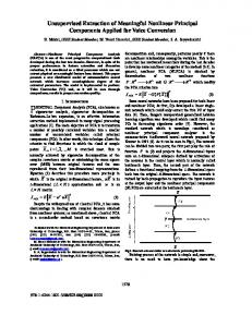
Fig. 1. Two radiator cell waveguide simulator. TE mode propagates in each waveguide radiator. Radiators are separated by zero-thickness metal septum. Frequency: 10 GHz.
pointed into empty space. When a waveguide simulator is modeled on the computer and a grating lobe is present, extraction of the radiator reflection coefficient from the -parameter data is not completely straightforward. In this paper, we present a method for extracting the reflection coefficient of the radiating element from the waveguide simulator data.
S
II. DISCUSSION Fig. 1 shows a simple waveguide simulator. There are three physical ports to this simulator. At the top of the figure are two waveguide radiating elements (ports 2 and 3), which, in an actual array, would be connected to phase shifters or T/R modules and an RF beamformer. Each of the waveguide radiator cells propagates a single TE10 mode (not to be confused with the simulator modes). For this example, the element spacing and frequency have been chosen so that a grating lobe will appear when the beam is scanned past 18�. At the bottom of the figure, the waveguide simulator propagates three modes. Note that one narrow wall of the simulator is a perfect magnetic conductor and the other is a perfect electric conductor (creating a compact structure equivalent to a four-cell all-metal simulator). Fundamentally, the reflection coefficient of each propagating mode at the waveguide simulator port gives the radiator reflection coefficient at a discrete scan angle, which is a function of the frequency of analysis, the mode's field configuration, and the cutoff frequency. In our example, the three modes correspond to three pairs of -plane scan angles, 69.43�, 629.46�, and 655.05�. Table I shows the -parameter data, simulator mode propagation coefficients and corresponding scan angles obtained from the computer model. When a grating lobe is not present in real space, we can interpret the -parameter data obtained from a computer waveguide simulator in a straightforward manner. For a scan angle of 9.4� , the magnitude of 11 , mode 1 is the phased-array radiator reflection coefficient in the infinite array environment. Any energy reflected at the radiator/simulator interface reflects back in mode 1 only. In contrast to mode 1, simulator modes 2 and 3 are coupled together. As Eisenhart shows in [1], the existence of a grating lobe is the cause. When the array is scanned to +29.46� (simulator mode 2), a grating lobe will appear at 055.05� (simulator mode 3). Conversely, when the
H
S S
0018–926X/00$10.00 © 2000 IEEE
S
634
IEEE TRANSACTIONS ON ANTENNAS AND PROPAGATION, VOL. 48, NO. 4, APRIL 2000
TABLE I SCATTERING PARAMETER MATRIX, MODE PROPAGATION CONSTANTS AND SIMULATOR SCAN ANGLES. PORT 1 IS WAVEGUIDE SIMULATOR, AND PORTS 2 AND 3 ARE RADIATING ELEMENT PORTS. FREQUENCY: 10 GHz. HIGHLIGHTED PARAMETERS ARE COUPLED SIMULATOR MODES 2 and 3
array is scanned to +55.05�, a grating lobe appears at 029.46�. From the symmetry of this behavior, we can conclude that the radiator reflection coefficient must be the same for either scan angle, a fact that appears to be contradicted by the highlighted data in Table I. Hence, the simulator port reflection coefficient of either mode cannot be the true reflection coefficient seen by the radiating element. III. EXTRACTION METHOD To determine the radiator reflection coefficient, we refer to Fig. 2, which shows a five-port network model of the waveguide simulator in Fig. 1. Each port of the model represents one of the propagating modes, one in each radiator and three in the waveguide simulator. The circled numbers identify the physical ports of the simulator. As Eisenhart states in [1], we can determine the radiator reflection coefficient from either the simulator port (looking in) or the radiating element port (looking out). When a grating lobe is not present, this task is easiest from the simulator side. However, when a grating lobe is present, we must resort to looking out from the radiator side. Because the array is infinite and all radiating elements are identical, the radiator reflection coefficient should be the same in either radiating element port, as our analysis will show. In Fig. 2, 04 and 05 are the unknown radiator reflection coefficients we seek. In terms of the five-port S -parameters, we can write
Fig. 2. Five-port network representation of two radiator cell, waveguide simulator. Each port represents a propagating mode. Circled numbers denote physical ports. 0 and 0 are unknown feed coefficients.
= S41 a1 + S42 a2 + S43 a3 + S44 a4 + S45 a5 b5 = S51 a1 + S52 a2 + S53 a3 + S54 a4 + S55 a5 :
Equations (1) and (2) with (3) give the radiating element reflection coefficients
b4
Now consider that the array is transmitting only. Then, a1 = a2 = a3 = 0 because no energy is being received from the simulator port. The above equations simplify considerably
= S44 a4 + S45 a5 b5 = S54 a4 + S55 a5 : b4
04 = b4 =a4 = S44 + S45 a5 =a4
(1)
05 = b5 =a5 = S54 a4 =a5 + S55 :
(2)
The ratio a4 =a5 is an unknown. However, we only want to transmit the two coupled modes represented by b2 and b3 . Thus, we set b1 equal to zero, which gives
= S14 a4 + S15 a5 = 0:
We solve this equation for the unknown ratio to get a4 =a5
= 0S15 =S14 :
(4)
05 = 0S54 S15 =S14 + S55 :
(5)
If we substitute the values from Table I into these equations, we get and 05 = 0:0094; 38:1� , which are identical within the accuracy of the S -parameter data we used. We have verified this method against published waveguide array data in which a grating lobe was present [2] and obtained excellent agreement. The same method can be applied to simulators with more radiator cells; the computations just become more tedious and should be done with a computer. Designers of limited-scan arrays sometimes use highly directive radiators to suppress grating lobes. Even so, our formulation is general and still valid; however, in this case it is unnecessary. If the level of suppression is high, the coupling between the waveguide simulator modes corresponding to the main beam and grating lobes will approach zero and the magnitude of the reflection coefficient at the grating lobe angle will approach unity. Consequently, we can use the conventional procedure of calculating the reflection coefficient from the waveguide simulator port with reasonable accuracy.
04 = 0:0101; 39:3�
When we solve for the reflection coefficients of the radiating elements, we get
b1
04 = S44 0 S45 S14 =S15
(3)
IEEE TRANSACTIONS ON ANTENNAS AND PROPAGATION, VOL. 48, NO. 4, APRIL 2000
IV. CONCLUSION We have described a method for extracting the reflection coefficient of a radiating element from waveguide simulator data when one or more grating lobes are present. Because the waveguide simulator modes corresponding to the main beam and grating lobe become coupled, we must determine the radiating element reflection coefficient from the radiating element port, rather than from the waveguide simulator port. However, the reflection coefficient of each radiating element contains contributions from all the waveguide simulator modes. Viewed differently, if we excite the radiating element port mode, all three propagating modes in the simulator port are excited (see data in Table I); thus, the radiating element port reflection coefficients are not meaningful without manipulation. To excite a pair of modes corresponding
635
to a main beam and grating lobe (the example presented in this paper), we must adjust the radiating element excitations to suppress the undesired modes. This procedure is analogous to setting phase shifters in an actual phased array to produce a desired progressive phase distribution across the array.
REFERENCES [1] R. L. Eisenhart, “Antenna element and array simulation with commercial software,” in Finite Element Software for Microwave Engineering, T. Itoh, G. Pelosi, and P. Silvester, Eds. New York: Wiley, 1996. [2] G. F. Farrel and D. H. Kuhn, “Mutual coupling in infinite planar arrays of rectangular waveguide horns,” IEEE Trans. Antennas Propagat., vol. AP-16, pp. 405–414, July 1968.