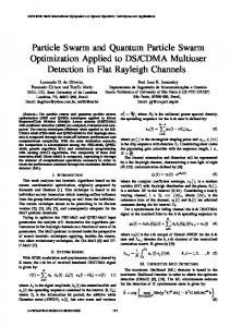
Particle swarm optimization, coplanar waveguide, inductor, circuit modelling. 1. Introduction ... air-bridge is used to connect the inner port of the spiral to the output CPW. ... Figure 1. The CPW square spiral inductor (number of turns N = 3). The lumped ... obtained using HFSS, the following expressions can be used to ...
International Journal of Modelling and Simulation, Vol. 28, No. 2, 2008
PHYSICAL MODELLING AND PARTICLE SWARM DESIGN OF COPLANAR WAVEGUIDE SQUARE SPIRAL INDUCTOR N.I. Dib∗ and J.I. Ababneh∗
not fully presented in the paper. In [16], a lumped element equivalent circuit was proposed to model the CPW spiral inductor. The elements of this circuit were found using the quasi-static finite difference method (FDM). In [17], a square multilayered CPW spiral inductor was presented, measured, and analyzed using a full-wave package. However, no equivalent circuit model was proposed. In this paper, simple lumped element equivalent circuit, similar to that used in [16], is used to model the CPW spiral inductor. The circuit is based on physical modelling which takes into consideration the parasitic effects inherent in the CPW spiral inductor. Closed form expressions are used to evaluate the elements in the equivalent circuit. The inductance expressions presented in [18, 19] are used to find the inductance of the CPW spiral inductor. Our results are in good agreement with the FDM results from [16], and full-wave results obtained using HFSS software [21]. Moreover, the particle swarm optimization (PSO) technique [22–27] is used to design the spiral inductor. Specifically, given the desired inductance, the PSO is used to find the dimensions and the number of turns of the spiral. The details of the PSO algorithm are presented in Section 3.
Abstract This paper presents simple lumped element equivalent circuit for the coplanar waveguide (CPW) square spiral inductor. The circuit is based on physical modelling which takes into consideration the parasitic effects inherent in the CPW spiral inductor.
The
obtained scattering parameters are in good agreement with fullwave and quasi-static results available in the literature.
Such a
simple circuit model is suitable for computer aided design (CAD) purposes, and could be used along with optimization techniques for synthesis purposes. Moreover, the particle swarm optimization (PSO) technique is used to design the CPW inductor. Specifically, given the desired inductance, the PSO is used to find the dimensions and the number of turns of the spiral.
Key Words Particle swarm optimization, coplanar waveguide, inductor, circuit modelling
1. Introduction With the growing demand for RF and mobile communications, many efforts concentrated on developing design rules for MMIC spiral inductors [1–20]. In general, the main parameter that has been studied is the inductance of the spiral. Most of these papers used the technique proposed by Greenhouse [10], which sums all the mutual and self inductances of the spiral segments using closed form expressions. Recently, three simple closed form expressions have been proposed in [18, 19] to evaluate the inductance of planar spirals of different shapes. Most of the above-mentioned papers dealt with microstrip spiral inductors, while very few papers dealt with the coplanar waveguide (CPW) spiral inductors [14–17]. In [15], a rather complicated distributed element equivalent circuit was proposed to analyze the CPW spiral inductors. Though novel, the details of this technique are
2. Equivalent Circuit Model The CPW spiral inductor modelled here is shown in Fig. 1 (a three-turn spiral is shown). The spiral under consideration is a square one of side length d, which is usually the case in practice because of the ease of its layout. An air-bridge is used to connect the inner port of the spiral to the output CPW. When analyzing this CPW square spiral inductor, the following parameters need to be specified: 1. d: the outer dimension of the spiral. 2. N : the number of turns (restricted to integer multiple of 0.5). 3. W : the spiral strip width. 4. S: the spacing between the spiral turns. 5. Sg : the distance between the outermost turn and the ground plane. 6. Ha : the height of the air-bridge. 7. Wa : the width of the air-bridge. 8. t: the metallization thickness. 9. ρ: the metallization resistivity.
∗
Electrical Engineering Department, Jordan University of Science and Technology, P.O. Box 3030, Irbid 22110, Jordan; e-mail: {nihad, ababnehj}@just.edu.jo Recommended by Prof. Azim Houshyar (paper no. 205-4767)
219
Cs = Ccoupling + Cair-bridge (� − �N )t Ccoupling = �0 S W Wa Cair-bridge = n�0 Ha
(1) (2) (3)
where � is the total mean length of the spiral, and �N is the mean length of the innermost turn. Essentially, Ccoupling is approximated as the side-wall parallelplate capacitance between the turns [20]. The fringing effects are neglected. �N is subtracted from the total length � since the innermost turn has no sidewall capacitance. In addition, Cair-bridge is approximated as a parallelplate capacitance between the air-bridge and the spiral metallization. Such an approximation is valid since the height of the bridge is typically 3–5 μm which is very small compared to the bridge width and the spiral strip width. The factor n is the number of turns that the air-bridge crosses (n = N if N is an integer, and n = N − 0.5 if N is not an integer). 4. The parallel capacitors C1 and C2 are used to model the capacitance between the spiral (mainly the outermost turn) and the ground plane. Usually, the distance to the ground Sg is large to reduce its effect on the spiral response. However, it has been shown in [15] that the ground effect needs to be included to get more accurate results. This is done by noticing that the path between the outermost turn and the ground resembles a slotline of width Sg [15]. The capacitance of this slotline can be approximated as half the capacitance of a CPW (CCP W ) with centre conductor width W and slot width Sg . After several numerical experiments and comparing the S-parameters obtained from our model to those available in the literature and those obtained using HFSS, the following expressions can be used to approximate C1 and C2 :
Figure 1. The CPW square spiral inductor (number of turns N = 3).
The lumped element equivalent circuit shown in Fig. 2 is used to model the CPW spiral inductor. This circuit should be applicable up to the first resonant frequency of the inductor, which is the frequency range of interest as it represents the region where the spiral acts as an inductor. The lumped elements of this circuit are obtained as follows:
Figure 2. The lumped element equivalent circuit of the CPW square spiral inductor. 1. To evaluate the inductance L of square spirals, any of the three simple expressions proposed in [18, 19] could be used. These expressions were fully tested in [18] and proved to be accurate enough for design and optimization of practical square spiral inductors. It should be noted that the value of the inductance L is independent of the dielectric substrate, therefore, the formulas were obtained assuming spirals in free-space. For a grounded substrate, the expression presented in [11] can be used to evaluate the inductance L.
�
CCP W C1 = 2 C1 C2 = √ N +1
� (4 d)
(4) (5)
It should be noted that the values of these parallel capacitances have to be different so that the phases of S11 and S22 are not equal.
2. The resistance R can be computed using the expressions from [1] or [13, 19]. These expressions take the skin effect into account. Thus, the resistance is a function of frequency.
3. PSO Algorithm PSO is a stochastic optimization technique that was first developed in 1995 by Eberhart and Kennedy [22–27]. It is a global optimization algorithm that has been effectively used to solve multidimensional discontinuous optimization problems in a variety of fields [28]. The algorithm is an attempt to simulate the swarming behaviour of birds, bees, fish, etc. It aims at increasing the probability of encountering the global minimum (or maximum), without performing an exhaustive search of the entire parameter
3. The series capacitor Cs models the parasitic capacitive coupling between the input and output ports of the inductor. Both the crosstalk between the adjacent turns and the overlap between the spiral and the air-bridge contribute to this capacitance Cs . The following approximate expression is used to evaluate this capacitance: 220
4. Update of velocity and position: The following substeps are carried out for each particle: (a) Velocity update: The velocity of the mth particle in the nth dimension (vmn ) is updated according to the following equation:
space. The performance of the PSO is comparable to other stochastic optimization technique like genetic algorithm (GA) and simulated annealing [27]. In addition, the PSO outperformed the GA in certain instances [29]. One of the key advantages of PSO is the ease of implementation in both the context of coding and parameter selection. The algorithm is much simpler and intuitive to implement than complex, probability-based selection and mutation operators required for evolutionary algorithms such as the GA. Similar to evolutionary algorithms, the PSO starts with an initial population of individuals (to be termed swarm of particles). Each individual (particle) in the swarm is randomly assigned an initial position and velocity. The position of the particle is an N -dimensional vector that represents a possible set of the unknown parameters to be optimized. Each particle in the swarm starts from its initial position at its initial velocity with the goal of finding the position with global minimum (or maximum). During the algorithm search, the velocity and position of each particle is updated based on the individual and the swarm experience. The goodness of the new particle position (possible solution) is measured by evaluating a suitable objective or fitness function. This process of updating velocities and positions continues and results in that one of the particles in the swarm finds the position with best fitness (global minimum or maximum). Eventually, all the particles will be drawn to this position since they will not be able to find a better one. The main steps of the PSO algorithm can be summarized in the following steps:
t t−1 t−1 vmn = w vmn + c1 R1 (pbesttmn − xmn ) t−1 + c2 R2 (gbesttmn − xmn )
(6)
where xmn represents the position of the mth particle in the nth dimension. The superscripts t and t − 1 denote the time index of the current and the previous iterations, R1 and R2 are two random numbers between 0 and 1 generated by uniformly distributed random functions. The relative weights of the personal best position versus the global best position are specified by the parameters c1 and c2 , respectively. Both c1 and c2 are typically set to a value of 2.0 [31]. The parameter w is called the “inertial weight”, and it is a number in the range [0–1] that specifies the weight by which the particle’s current velocity depends on its previous velocity, and the distance between the particle’s position and its personal best and global best positions. It has been shown in [30] that the PSO algorithm converges faster if w is linearly damped with iterations, for example starting at 0.9 at the first iteration and finishing at 0.4 in the last iteration. Guidelines for selecting and optimizing the PSO parameters are detailed in [31–36]. (b) Position update: The position of the mth particle in the nth dimension is updated according to:
1. Definition of the solution space : The minimum and maximum values for each dimension in the N dimensional optimization problem are specified to define the solution space of the problem. The solution space is the accepted parameters values and it is usually governed by the typical values of the parameters and their constraints. 2. Definition of the fitness function: The fitness function is a problem-dependent parameter which represents a method that can be used to evaluate and measure the goodness of a position (N -dimensional vector) that represents a valid solution of the problem. It should be carefully selected to represent the goodness of the solution and return a single number. 3. Random initialization of the swarm positions and velocities : The positions and velocities of the particles are randomly initialized. However, it is preferred that they are randomly initialized within the solution space for faster convergence. The number of particles is problem dependent, and for most engineering problems a swarm size of 30 is good enough [30]. To complete the initialization step, the initial position of each particle is labelled as the particle’s best position (pbest). In addition, the position of the particle with best fitness among the whole swarm is labelled as the global best position (gbest). In this context, the word best could mean highest or lowest depending on whether the problem at hand is a minimization or maximization problem.
t xtmn = xt−1 mn + �t vmn
(7)
where �t represents a given time step (usually chosen to be one). (c) Fitness evaluation: The fitness of the updated N -dimension position in the previous step is evaluated. If the returning number is better than that of the pbest, this updated N -dimension position is labelled as the new pbest. In addition, if the returning number is better than that corresponding to gbest, the updated N -dimension position is also labelled as the new gbest. 5. Checking the termination criterion: The algorithm may be terminated if the number of iterations reaches a pre-specified maximum number of iterations or the returning number corresponding to gbest is close enough to a desired number. If none of these conditions is satisfied, return to step 4. In this work, the PSO is used to synthesize the spiral inductor. The goal is to find the spiral inductor parameters (N , d, W , S) to achieve a desired inductance value Ldes . The fitness function for the problem at hand is formulated as: F itness = |Ldes − Lcal | 221
(8)
Figure 3. Magnitude and phase of S21 for the CPW spiral inductor obtained using the circuit model (solid lines) compared to results from [16] (symbols). W = 25 μm, S = 5 μm, Ha = 3 μm, Wa = 25 μm, Sg = 50 μm, t = 3 μm, h = 635 μm, �r = 13. d = 185 μm for N = 2.5; d = 240 μm for N = 3.5; d = 300 μm for N = 4.5.
Figure 4. Scattering parameters for the CPW spiral inductor obtained using the circuit model (solid lines) compared to results obtained using HFSS (symbols). W = 30 μm, S = 10 μm, Ha = 3 μm, Wa = 30 μm, Sg = 70 μm, t = 0 μm, h = 635 μm, �r = 13, d = 300 μm, N = 3. ing dimensions: N = 3, d = 300 μm, S = 10 μm, W = 30 μm, Sg = 70 μm, Ha = 3 μm, Wa = W , and t = 0. Results obtained using HFSS [21] are also shown in the same figure. Our results are in good agreement with the HFSS results. It can be seen that the phase of S11 is different from the phase of S22 since the spiral is a non-symmetric structure. Other spirals with the same dimensions but with different number of turns were also analyzed and a similar agreement was obtained.
where Lcal is the calculated inductance using the three approximate expressions given in [18]. In our implementation of the PSO algorithm, a swarm size of 25 particles and number of iterations between 500 and 1000 were used. Both parameters c1 and c2 were set to a value of 2. The inertia weight was initially set to 0.9, and decreased linearly to 0.4 during the iteration process. This allows the initial large value to enhance the global exploration, while the final low value facilitates local exploration of the solution space. The results of this implementation of the PSO to design the spiral inductor are given in Section 5.
5. PSO Results The PSO algorithm was used to design the spiral inductor by finding some (or all) of its main parameters (N , d, W , S) that result in a certain desired inductance value Ldes . Two different cases were considered: In the first case, some of the spiral inductor parameters were set to some fixed values (desired or manufacture settings) and the remaining parameters were obtained using the PSO. In the other case, all the spiral inductor main parameters are searched by the PSO to obtain a desired inductance value. In both cases, the search process is constrained to some acceptable typical values (2 ≤ N ≤ 15, 100 μm ≤ d ≤ 480 μm, 2 μm ≤ W ≤ 0.3d, 2 μm ≤ S ≤ 3W ) as in [18]. A wide range of inductors (0.5–100 nH), can be designed using these typical values. Tables 1–4 give the results of designing several spiral inductors. In each table, the values of the remain-
4. Circuit Model Results First, the CPW spiral inductors analyzed in [16] are modelled. Fig. 3 shows the scattering parameters obtained from the circuit model compared to those obtained using FDM [16]. It can be seen that the agreement is very good which validates our proposed circuit model. It should be noted that the CPW spirals analyzed in [16] are not exactly square. The inductance values for the analyzed spirals are approximately as follows: L = 0.8 nH for the N = 2.5 spiral, L = 1.7 nH for the N = 3.5 spiral, and L = 3.3 nH for the N = 4.5 spiral. As another example, Fig. 4 shows the scattering parameters for a 1.94 nH CPW spiral inductor with the follow222
Table 1 Design of Spiral Inductor Using the PSO (N = 5, d = 200 μm, W = 5 μm) Ldes
Modified Wheeler
Current Sheet
S
S
Lcal
ing or all the required parameters to obtain a desired inductance value with some acceptable error are given. In addition, the tables show the calculated inductance values using the three different approximate expressions [18] of the spiral inductor. These expressions were termed in [18] as: “Modified Wheeler”, “Current Sheet”, and “Monomial Expression”. These expressions were used to calculate the spiral inductor value Lcal used in the fitness function (8) which usually results in slightly different parameters values due to the differences between the expressions. In the first three tables, some of the spiral inductor parameters were fixed to some desired values and the remaining parameters were obtained using the PSO. For example, in Table 2, N was set to a value of 10 and d was set to a value of 300 μm. Our selection of fixed parameters in these tables was random and just to show the validity of this option. However, the selection of the fixed parameters values determines the range of the values of the inductance that can be designed. Therefore, the selection of the fixed parameters requires special attention if certain desired inductance values are required. On the other hand, all the parameters that result in a desired inductance value were searched using the PSO algorithm in Table 4. As can be seen from the tables, the calculated inductor values are equal or very close to the desired values. The error between the calculated and the desired value may be controlled by careful selection of the fixed parameters. Furthermore, as the number of the fixed parameters decreases the error between the calculated and the desired values decreases as shown in Tables 2–4. This is due to the fact that reducing the number of the fixed parameters increases the solution space searched by the PSO algorithm. This widening of the solution space results in the availability of more than one solution, since the problem at hand is a multisolution problem. Therefore, there is more freedom (more sets of parameters) in selecting the required parameters (one of many solutions) that result in the desired inductor value. This situation is demonstrated by giving two sets of parameters that result in the desired inductor value in Tables 2–4.
Monomial Expression
Lcal
S
Lcal
2
18.5 2.010 18.7 2.078 18.7 2.140
4
10.8 3.999 10.7 4.013 11.4 4.014
5.5
6.8 5.512
6.7 5.492
7.1 5.493
6
5.7 6.004
5.4 6.077
5.8 6.010
7
3.7 6.997
3.6 6.999
3.6 6.979
8
1.9 8.014
1.9 8.027
1.7 7.976
S in µm, and inductance in nH.
Table 2 Design of Spiral Inductor Using the PSO (N = 10, d = 300 μm) Ldes
Modified Wheeler W
12
15
S
Current Sheet
Lcal
W
S
Monomial Expression
Lcal
W
S
Lcal
12.9 2.2 11.996 10.4 5.1 12.436 8.5 6.8 12.003 11.1 4.2 11.996 8.6
7.1 12.436 7.1 8.5 11.996
8.7 5.3 14.998 5.1
9.5 14.990 8.5 5.2 14.999
9.6 4.3 14.997 4.2 10.5 14.990 5.5 8.9 15.004 21
5.6 6.2 21.013 6.6
5.1 21.014 4.1 8.1 21.002
7.4 4.2 21.013 4.8
7.1 21.014 6.8 4.6 21.001
Dimensions W , and S in µm, and inductance in nH. Two sets of valid solutions are shown for each case.
Table 3 Design of Spiral Inductor with N = 8 Using the PSO
Table 4 Complete Design of Spiral Inductor Using the PSO Ldes
Ldes
5
26
50
Modified Wheeler Lcal = Ldes
Current Sheet Lcal = Ldes
Monomial Expression Lcal = Ldes
d
d
d
W
S
W
S
W
N 3
S
170 3.1 7.8 134 2.1
5.6 188 5.6
6.6
170 6.6 3.8 134 4.2
3.2 162 6.9
2.4
34
7
325 4.6
5.4
488 5.5 5.1 436 4.8
4.5 483 3.7
7.9
477 5
2.8 444 2.5
7.4
5
343 1.2
d
W
Current Sheet Lcal = Ldes S
70
d
W
S
N
d
W
S
2 399 23.8 2.6
4 472 55.3 4.1
3 386 39
5 182 11.8 2.9
3 338 31.2 2.5
3.7
8 465 12.1 2.9
13 493
8 459 11.9 2.5 13 460 13.9 2.7 8 450 10.9 3
9.8 2.9 14 423
14 483 10 100
N
Monomial Expression Lcal = Ldes
2 433 27.4 6.6
12 471 15.4 2.4
336 3.4 7.5 499 6.3 12.6 428 5.6 12.7 347 2.6 9.2 366 5.6
Modified Wheeler Lcal = Ldes
2.6 14 456
7 451
8.9 2.2
12 490
9.2 2.2
9.2 2.2 13 431
7.4 2.1
8
2
15 472
7.6 2
15 472
7.6 2
15 477
7.3 2
14 469
7
14 499
7.9 2.1 15 488
7.7 2
2
Dimensions d, W , and S in µm, and inductance in nH. Two sets of valid solutions are shown for each case.
Dimensions d, W , and S in µm, and inductance in nH. Two sets of valid solutions are shown for each case.
223
6. Conclusions
Transactions on Microwave Theory and Techniques, 41(8), 1993, 1307–1315.
Simple lumped element equivalent circuit for the CPW square spiral inductor have been proposed and studied. This circuit takes into consideration the parasitic effects inherent in the CPW spiral inductor. The obtained results are in good agreement with those published in the literature, and HFSS results. Such a simple model is appropriate for CAD purposes. Moreover, it has also been demonstrated that the design of spiral inductors can be easily performed using the PSO technique.
[17] D. Budimir, I. Robertson, Q. Wang, & A. Rezazadeh, Design of coplanar waveguide multilayer square spiral inductors for monolithic microwave integrated circuits, International Journal of RF and Microwave Computer-Aided Engineering, 9(2), 1999, 86–92.
References
[20] S. Kythakyapuzha, Modelling of spiral inductors and transformers, M.S. Thesis, Kansas State University, 2001.
[1] E. Pettenpaul, H. Kapusta, A. Weisgerber, H. Mampe et al., CAD models of lumped elements on GaAs up to 18 GHz, IEEE Transactions on Microwave Theory and Techniques, 36(2), 1988, 294–304. [2] R. Shimon, D. Scherrer, D. Caruth, I. Middleton et al., Accurate passive component models in CPW for 50 GHz MMICs, 1997 IEEE MTT-S Int. Microwave Symposium Digest, Vol. 2, 769– 772. [3] K. Beilenhoff, W. Heinrich, & H. Hartnagel, Analysis of MIM series capacitances for coplanar MMICs, 8th Congr. Microwaves Optron. Dig., Sindelfinger, Germany, 1995, 124–128. [4] T. Vaupel & V. Hansen, Electrodynamic analysis of combined microstrip and coplanar/slotline structures with 3-d components based on a surface/volume integral-equation approach, IEEE Transactions on Microwave Theory and Techniques, 47(9), 1999, 1788–1800. [5] Y. Shih, C. Pao, & T. Itoh, A broadband parameter extraction technique for the equivalent circuit of planar inductors, 1992 IEEE MTT-S Int. Microwave Symposium Digest, Vol. 3, 1345– 1348. [6] D. Krafcsik & D. Dawson, A closed-form expresion for representing the distributed nature of the spiral inductor, 1986 IEEE MTT-S Int. Microwave Symposium Digest, 87–92. [7] Y. Koutsoyannopoulos & Y. Papananos, Systematic analysis and modelling of integrated inductors and transformers in RF IC design, IEEE Transactions on Circuits and Systems II, 2000, 699–713. [8] Z. Hejazi, P. Excell, & Z. Jiang, Accurate distributed inductance of spiral resonators, IEEE Microwave and Guided Wave Letters, 8(4), 1998, 164–166. [9] Z. Jiang, P. Excell, & Z. Hejazi, Calculation of distributed capacitances of spiral resonators, IEEE Transactions on Microwave Theory and Techniques, 45(1), 1997, 139–142. [10] H. Greenhouse, Design of planar rectangular microelectronic inductors, IEEE Transactions on Parts, Hybrids, and Packaging, 1974, 101–109. [11] W. Tang & Y. Chow, Simple CAD formula for inductance calculation of square spiral inductors with grounded substrate by duality and synthetic asymptote, Microwave and Optical Technology Letters, 34(2), 2002, 93–96. [12] S. Leong, Design, optimization of RF spiral inductors using scalable compact and accurate models, Analog Integrated Circuits and Signal Processing, 37, 2003, 165–177. [13] C. Yue & S. Wong, Physical modelling of spiral inductors on silicon, IEEE Transactions on Electron Devices, 47(3), 2000, 560–568. [14] P. Pogatzki, R. Kulke, T. Sporkmann, D. Kother, et al., A comprehensive evaluation of quasi-static 3D-FD calculations for more than 14 CPW structures—lines, discontinuties and lumped elements, 1994 IEEE MTT-S Int. Microwave Symposium Digest, Vol. 2, 1289–1292. [15] I. Huynen, Novel fast multiline analysis of parasitic effects in CPW inductors for MMIC’s, IEEE Microwave and Guided Wave Letters, 8(2), 1998, 72–74. [16] M. Tuko, M. Naghed, & I. Wolff, Novel 18/36 GHz MMIC GaAs FET frequency doublers in CPW techniques under the consideration of the effects of coplanar discontinuities, IEEE
[21] HFSS Software, Ansoft Corporation, PA, USA.
[18] S. Mohan, M. del Mar Hershenson, S. Boyd, & T. Lee, Simple accurate expressions for planar spiral inductances, IEEE Journal of Solid-State Circuits, 34(10), 1999, 1419–1424. [19] S. Mohan, The design, modelling and optimization of on-chip inductor and transformer circuits, Ph.D. Dissertation, Stanford University, 1999.
[22] R.C. Eberhart & J. Kennedy, A new optimizer using particle swarm theory, Proc. Sixth International Symposium on Micromachine and Human Science, Nagoya, Japan, 1995, 39–43. [23] J. Kennedy & R.C. Eberhart, Particle swarm optimization, Proc. IEEE International Conference on Neural Networks, Piscataway, NJ, 1995, 1942–1948. [24] J. Kennedy & R.C. Eberhart, A discrete binary version of the particle swarm algorithm, Proc. IEEE International Conference on Systems, Man, and Cybernetics: Computational Cybernetics and Simulation, Vol. 5, 1997, 4104–4108. [25] J. Kennedy, R.C. Eberhart, & Y. Shi, Swarm intelligence (San Francisco: Morgan Kaufmann Publishers, 2001). [26] J. Kennedy & R. Mendes, Population structure and particle swarm performance, Proc. Congr. Evolutionary Computation (CEC 02), Vol. 2, 2002, 1671–1676. [27] J. Kennedy & J.M. Spears, Matching algorithms to problems: An experimental test of the particle swarm and some genetic algorithms on the multimodal problem generator, Proc. IEEE World Congr. Computational Intelligence Evolutionary Computation, 1998, 78–83. [28] R.C. Eberhart & Y. Shi, Evolving artificial neural networks, Proc. Int. Conf. Neural Networks Brain, Beijing, P.R.C., 1998. [29] B. Brandstatter & U. Baumgartner, Particle swarm optimization-mass-spring system analogon, IEEE Transactions on Magnetics, 38(2), 2002, 997–1000. [30] J. Robinson & Y. Rahmat-Samii, Particle swarm optimization in electromagnetics, IEEE Transactions on Antennas and Propagation, 52(2), 2004, 397–402. [31] I.C. Trelea, The particle swarm optimization algorithm: Convergence analysis and parameter selection, Information Processing Letters, 85, 2003, 317–325. [32] M. Clerc & J. Kennedy, The particle swarm—explosion, stability, and convergence in a multidimensional complex space, IEEE Transactions on Evolutionary Computation, 6(2), 2002, 58–73. [33] A.I. El-Gallad, M.E. El-Hawary, A.A. Sallam, & A. Kalas, Enhancing the particle swarm optimizer via proper parameters selection, Canadian Conference on Electrical and Computer Engineering, 2002, 792–797. [34] Y. Shi & R. Eberhart, A modified particle swarm optimizer, Proc. IEEE World Congr. Computational Intelligence Evolutionary Computation, 1998, 69–73. [35] Y. Shi & R. Eberhart, Empirical study of particle swarm optimization, Proc. Congr. Evolutionary Computation (CEC 99), Vol. 3, 1999, 1945–1950. [36] F. van den Bergh & A.P. Engelbrecht, Effects of swarm size on cooperative particle swarm optimizers, Proc. Genetic and Evolutionary Computation Conference 2001, San Francisco, USA, 2001.
224
Jehad I. Ababneh received his B.S. degree from Jordan University of Science and Technology, Irbid, Jordan, in 1989, his M.E. degree from Tennessee State University, Nashville, TN, USA, in 1998 and his Ph.D. degree from Wichita State University, Wichita, KS, USA, in 2001, all in Electrical Engineering. He was a communication engineer with the Jordan Armed Forces, from 1990–1996. In 2001, he joined the American Tower Corporation, Georgia, USA, as a senior engineer developing and delivering courses in wireless communication. He is currently with the electrical engineering department at Jordan University of Science and Technology, Irbid, Jordan. His research interests include wireless communication, artificial intelligence, digital signal and speech processing.
Biographies Nihad I. Dib obtained his B.Sc. and M.Sc. degrees in EE from Kuwait University in 1985 and 1987, respectively. He obtained his Ph.D. degree in EE (major in Electromagnetics) in 1992 from University of Michigan, Ann Arbor. Then, he worked as an assistant research scientist in the radiation laboratory at the same school. In September 1995, he joined the EE Department at Jordan University of Science and Technology (JUST) as an assistant professor, and became an associate professor in September 2000. From July 2001 to March 2003, he was a senior research engineer at Ansoft Corporation, NJ, USA, on sabbatical leave from JUST. His research interests are mainly in computational electromagnetics and modeling of passive microwave circuits. Dr. Dib is a senior member of the IEEE.
225