graphical user interfaces (GUIs) in a distributed computing environment. ...
workstations, and is based on industry standards such as C++/C, RPC, SQL, and.
PICASSO: A User Interface Management System for Real-Time Applications Kjell Arne Barmsnes*, Arne Hornæs, Øystein Jakobsen, Rune Storkås OECD Halden Reactor Project Paper presented at workshop on “User Interfaces for Expert Systems”, London March 11-12, 1992
Abstract Picasso is a User Interface Management System supporting object-oriented definition of graphical user interfaces (GUIs) in a distributed computing environment. GUIs are defined using an interactive editor, however GUI components can be created, modified, and deleted at run-time. Attributes of GUI components can be connected to application data in order to reflect some state of an application. The Picasso system is designed to handle large amounts of application data in a real-time environment, and offers complete separation of user interface and application. The Picasso system runs on standard UNIX workstations, and is based on industry standards such as C++/C, RPC, SQL, and X-Windows.
1
Introduction
During the recent years software developers and users have become increasingly concerned about the quality of the software’s user interface. More powerful hardware has contributed to common use of graphical user interfaces. Improvements and changes in the user interface accounts for a substantial part of overall software development and maintenance costs [4]. As a consequence, there is a great demand for tools assisting system developers in easy creation and maintenance of graphical user interfaces. Such tools are commonly referred to as User Interface Management Systems (UIMS). An important characteristic with UIMS is that they encourage a rather loose coupling between the application program and the user interface. A direct effect of separating the application program and the user interface is more efficient development and maintenance of the total software system. The Picasso systems have been developed at the OECD Halden Reactor Project since 1984. The first version was running on proprietary platforms, whereas the current version being developed, is running on standard UNIX workstations. The current system is based on the following defacto industry standards: UNIX, C++/C, RPC, SQL, and X-Windows. The main application area for the Picasso systems has been within
*
Direct responses on this article to Kjell Arne Barmsnes, OECD Halden Reactor Project, P.B. 173, N-1751 Halden. Email:
[email protected]
1
the process control domain; simulators and emulation of existing control systems. The second version of Picasso, Picasso-2, has also been used to create the interface for an expert system application programmed in the G2 expert system shell (Gensym Corp). However, new functional requirements have led to a new version of Picasso that will cover a wider range of application areas such as expert systems, database systems, and network management systems. This paper describes the third version of the Picasso system, Picasso-3. The Picasso-3 system is currently being developed, and a first version is scheduled to December 1992.
2
System Overview
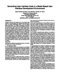
A typical problem with conventional user interface design is that even the slightest change in the user interface often implies large changes in application code — mainly because code for the user interface is scattered all over the application. A major requirement for a UIMS is therefore to offer complete separation of user interface and application code. A simple application is usually realized as one process, running under the control of the operating system on one computer. Non-trivial applications are however often realized as several processes, running on one or several computers* in a network. All processes as a whole, including their user interfaces, are considered one logical application by the end user. This means that a UIMS must support a client-server architecture, and must be able to operate in a distributed computing environment. Building good user interfaces is a science in itself requiring skills within the specific application area and within the field of man-machine interaction. Often these skills are held by people other than computer programmers. This means that a UIMS must offer some means of designing user interfaces without programming. An interactive graphics editor is an appropriate tool for this purpose. The editor must support the user interface designer not just in defining the graphical appearance of the interface, but also in defining the behaviour of the interface. Behaviour basically means how the interface responds to user interaction. Figure 1 shows the system architecture of Picasso. The major components in the architecture are: • Graphics Editor, GED — the tool used by the interface designer to define the application’s user interface. • User Interface Database — the database where Picasso stores user interface definitions for applications, i.e. the work done in the graphics editor is saved here. • Run-Time Manager, RTM — the part of Picasso that actually realizes the application’s user interface when the application executes. • Application Process — the part of the application that is independent of the user interface, typically programmed in a language like C. As already mentioned the application may well contain several UNIX processes running simultaneously, possibly also in duplicates. *
These computers might come from several vendors and run several blends of operating systems.
2
Picasso-3 Graphics Editor
Application Alpha
Application Beta
API
API
API
UI database
Picasso-3 Run-Time Manager
X-Windows Server
Figure 1 System overview. When the end user starts application Alpha from a terminal window, it will connect to the Run-Time Manager which in turn will load Alpha’s user interface from the UI database and realize it on the terminal. The graphics editor works like an ordinary application except for the fact that it is able to load, modify, and save other applications’ interfaces.
• Application Programming Interface, API — a library of C routines used by the application code to communicate with the Run-Time Manager. When an application is started, probably from a terminal window, the application process calls some initial API routines that set up the communication with the RunTime Manager. RTM in turn loads that application’s user interface from the database and realizes it on the terminal. RTM will then continue to handle events coming in from the end user (X-events) and from the processes (API calls). The processes will listen for and handle messages from RTM. When the application eventually shuts down, the Run-Time Manager will remove the application’s user interface from memory and close all associated windows. The graphics editor is a special application in the sense that it has the ability to operate on other applications’ interfaces. When the editor starts up, its own user interface is loaded by RTM, but in addition another interface description may be loaded and modified in the editor. The interface designer can then save the application’s new interface to the UI database.
2.1
The Graphics Editor
The graphics editor is a tool covering all aspects of the interface design process, some functions available to the interface designer are listed below: • Set up basic properties like text fonts, line styles, fill patterns, and colours. • Define reusable user interface components, known as classes, and connect to
3
already existing libraries of components. • Draw pictures using available graphic primitives and higher level interface components. • Define relations between pictures in order to set up hierarchies, chains or graphs of pictures, classes. • Set up dialogues to define how the interface should respond to user interaction. • Connect attributes to process data to define how the user interface is a function of the state of application processes. • Test the interface to verify that dynamic behaviour and dialogues work as intended. Testing the interface without actually starting the application is an important feature of the editor. One should note that the graphics editor is a Picasso application in its own right, meaning that the editor’s user interface is realized by the Run-Time Manager just like any other application. It also means that the editor can be used to modify the editor’s own user interface, and that is in fact how the editor was built using the classical method of bootstrapping: A rudimentary editor was used to define a slightly more sophisticated interface; the editor was then restarted with the new interface, giving new possibilities for adding even more features, and so on. The bootstrap procedure may well be carried out by end users in order to customize the editor for their needs, for example by extending the editor to cover their specific application area. The end user may also change the editor’s “look and feel” to match that of their everyday computing environment. The current version of the editor conforms to the OSF/Motif style-guide.
2.2
Inter-process Communication
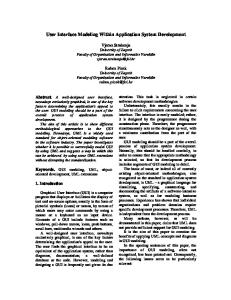
The Picasso Run-Time Manger (RTM) and the application processes communicate using CS*, which is a layer based on the Remote Procedure Call (RPC) protocol. CS, being independent of Picasso† but still developed as part of that project, comes in two parts: • CS Server — a communication server • CS Library — a C function library that is loaded with each process The communication is carried out as one process requesting services from another process. Each process makes its services available by informing the CS Server about them, and each request for a service is handed over to the CS Server which in turn forwards the request to the actual process and hands over the reply if any. This means that two processes do not communicate directly rather talk through the CS Server, as indicated in Figure 2. In Picasso typical services may be “display picture”, “update variable value”, or “shutdown”.
*
CS — Communication System.
†
RTM is just another process as far as CS is concerned.
4
PROCESS A
CS SERVER
g() { ... }
services
A B : :
A.f() A.g() B.h() :
CS Library
f() { ... }
CS Library
processes
PROCESS B
h() { ... }
Figure 2 CS structure. The CS server maintains a list of all available services of all active processes; in this case two processes A and B is connected, A has two services (functions) f() and g(), and B has one service h() available.
Indirect communication through a dedicated communication server have several advantages: • The requesting process need not know the whereabouts of the process offering the service because requests are forwarded by the CS Server, the only process who’s address is known by all processes. • If a process fails, gracefully or by dumping core, the process informs the CS Server that so happens. The CS Server hence knows the status of all processes and is able to place a useful diagnosis when a process requests a non-existent or disabled service. • Broadcast messages are easily handled as the CS Server simply duplicates such messages to all registered processes. • By centralizing information in a small and robust communication server, communication can hardly break completely down, even if individual processes fails. Asynchronous message handling is important in real-time systems. The requesting process then immediately receives a short “request sent” message from the CS Server, and the requested process sends a separate reply message when the service requested is eventually carried out. The CS Server keeps track of asynchronous requests and checks that replies are sent. The application programmer does not need to worry about the relatively low level CS protocol; the CS layer is hidden by the higher level functionality of the API functions. API routines are basically called to carry out data transfer between the application processes and RTM. Whenever a process changes values of data on which the user interface relies, the process should call appropriate API routines to inform RTM. Whenever RTM changes data on which the application relies, for example as a result of user interaction, RTM informs about new values by sending a message to the process. If the process contains huge amounts of data, sending new values to RTM as they change, becomes too time-consuming for a real-time system. RTM therefore has the possibility of subscribing to data it currently needs. This means that the process will only inform RTM about changes in values of data currently being subscribed to by RTM, i.e. data reflected in the user interface at that very moment. Series of subscribe and un-subscribe messages will therefore be passed from RTM to the connected processes.
5
3
Building User Interfaces
User interfaces are hierarchical in structure, and Picasso defines the following elements for building them: • Application — the highest level, defines the application as a whole, i.e. what appears as one logical application to the end user. • Process — the “UNIX” part of the application, probably programmed in C or some other high level language. An application may contain one or more processes. • Picture — what appears on the screen in an X window. Pictures can be moved, resized, and iconized, they appear on the screen and they disappear, and they may also be zoomed and panned. A large application may contain several hundred pictures. • Shape — graphic elements that make up the contents of a picture. They include primitive shapes such as line, rectangle, circle, and text, and more complex shapes like menus, lists, and graphs. The more complex shapes are in turn made up of several primitives or other less complex shapes. Complex shapes, realized as classes and instances, are covered in section 4. • Attributes, functions, and dialogues — are the lowest level elements that make up a user interface. They are used for storing and manipulating data and for defining the behaviour of the user interface, i.e. how the user interface should respond to events received from the end user or from the processes. Applications, pictures, and shapes may all contain attributes, functions, and dialogues.
3.1
Shapes and Attributes
TEXT
Picasso offers a variety of different primitive shapes used to make up a picture, some of which is shown in Figure 3.
TEXT
Figure 3 Many primitive shapes can be combined to make up a user interface. By setting attributes like foreground and background colours and patterns, linestyles, and arrows, even a limited set of primitives provide for almost unlimited freedom to design pictures.
The appearance of a shape is controlled by assigning values to its attributes. A rectangle shape has the following attributes: • Position, Width, Height, Rotation — The rectangle’s geometry. • Visibility — a boolean value controlling whether the rectangle should be visible or invisible.
6
• Border Width and Colour — the width and colour of the rectangle’s border lines. Transparency can be specified. • Fill Colours and Pattern — colours and pattern of the rectangle’s interior. Transparency can be specified. Different shapes have slightly different sets of attributes, but all attributes share one important feature: Their values can be bound to other attributes, application data, or combinations thereof, using expressions and functions. These assignments are dynamic in the sense that changes in the underlying data will automatically lead to changes in attribute values. If for example the width of a rectangle is bound to two application variables A and B by the expression A*3.14/2+B, then the rectangle will resize itself whenever the value of either A or B is changed. Arbitrarily complex expressions can be written using the Picasso function language covered in the next section. All attributes can be dynamically bound in this manner; a shape’s visibility attribute may for example be bound to a Picasso function returning a boolean value, thus making the shape appear and disappear based on data from the application. Shapes are not the only elements that may have attributes. Pictures have both predefined and may have user defined attributes, and even more global information can be stored as application attributes. Picasso classes typically contain attributes to hold local information, more on that in section 4.
3.2
Dialogues and Functions
The state of a user interface is at any time a function of the application data and end user actions. Dialogues define how the interface should respond to user interaction. A dialogue is made up of two parts: • Event Type — controls what should trigger the dialogue. An event type can typically be one of “Mouse button 1 toggled”, “Function Key F1 pressed”, “Cursor enters picture”, or “Shape resized”. • Action — defines what should happen when the dialogue is triggered. Typical actions include “Display picture X” and “Set new value V to attribute A”. The event type part of the dialogues include basic events more or less equal to X events, but also higher level events. The action part is expressed using the Picasso function language. Simple actions include calling pre-defined functions like displayPicture or rotateShape, and assignments like visibility = false or ForegroundBorderColor = Red. Complex actions, although more rarely needed, can be expressed using the full potential of the function language. The language is a C dialect also including some fundamental object-oriented features. A typical non-trivial action could be to check user input for legal values, a task that in most cases is the responsibility of the user interface and not the underlying application. This means that non-trivial interface behaviour can easily be set up and performed locally by the Run-Time Manager and need not be programmed as part of the application itself. This is vital for fulfilling the requirement of full separation of user interface and application.
7
3.3
Coordinate Systems
While X-Windows provides only pixel coordinates, Picasso supports user defined floating point coordinate systems. Each picture has its own user defined coordinate system and all shapes are defined within that system. The picture coordinate system is called the world, while the portion of the world visible within the picture’s window is called the viewport. Showing a smaller viewport, i.e. a smaller portion of the world, within the window means zooming into the picture. Moving the viewport around in the world means panning the picture. A typical example of user defined coordinates could be the use of latitude and longitude coordinates (assuming cylinder projection) when drawing objects on a map. We will see in the next section that pictures are not the only elements that have their own coordinate systems. Complex interface components, classes, can be defined in their own coordinate system and then instantiated, i.e. put into the world.
4
Object-Oriented User Interface Design
Graphical user interfaces are in most cases simplified models of scenarios from the real world. A scenario can be an overview of a physical process, consisting of pipes, valves, pumps, and tanks. These are all objects in the real world, and hence it is convenient to treat them as such in the user interface as well. As object-oriented programming languages are becoming increasingly popular, there is a need for object-oriented user interfaces that support creation of corresponding graphic objects. User interfaces often consist of a substantial number of graphic objects. However, many of these objects are of a similar type, and hence the design effort can be focused on the few different types, while numerous slightly different objects can be derived from the types; what is known as instantiation of classes.
4.1
Graphic Classes
In Picasso the type objects are realized with what is called graphic classes. A graphic class serves as a template for a set of instances possessing the same characteristics as the originating class. A graphic class consists of four main parts: • Attributes • Graphic shapes • Functions • Dialogues These four parts describe the state (attributes and graphic shapes) and the behaviour (functions and dialogues) of the class. In addition a class will have a coordinate system of its own, in order to make the class independent of any underlying coordinate system, such as a picture’s.
8
The attributes are local variables to the class, identified by a type and a name. All classes will have a set of pre-defined attributes such as Visibility (whether the class should be visible or not), Rotation, etc. User defined attributes can be added to a class by specifying attribute names and types. The attributes for a class are similar to the attributes described in section 3.1, except that class attributes may be user defined. Lets look at an example. Consider an OR gate with 2 input terminals and one output terminal. A corresponding class ORGate is defined with the following attributes: bool In1 = Simulator.status1; bool In2 = Simulator.status2; bool Out = In1 or In2; Here, In1 is logically connected to a variable status1 in an application program called Simulator. Whenever status1 changes its value, the class attribute In1 is updated accordingly. The graphic shapes are the visuals of the class, and can be graphic primitives (rectangle, circle, text, etc.) and instances of other classes. The graphic primitives have a set of pre-defined attributes that can be assigned to variables in a manner similar to that of a class. Hence, the update of graphics will also be taken care of automatically at any change of the corresponding attributes. The graphic shapes may be combined to give the ORGate class an appearance as illustrated in the figure below.
In1 Out In2
Figure 4 An OR-gate can be realized using a graphic class. The class is defined with two input terminals and one output terminal. The input terminals can be assigned to some application variables, in order to illustrate some logic state of an application
The functions are local functions to the class and can be viewed as the class’ interface to the surrounding world. The functions are typically used to encapsulate some operations on the class attributes and the graphic shapes. The class functions are defined in a proprietary language, however similar to C (See section 3.2). The functions described above would typically be used in dialogues. A dialogue consists of an event/action pair, and defines the behaviour of a class. A typical dialogue would be to change the colour of an object when the user “clicks” on it. A class dialogue is part of a class, and the “sensitive” area of the dialogue is defined by the size and position of the graphic class. Instances of Graphic Classes As described above, a graphic class is a type definition, and will serve as a template for slightly differing graphic objects, known as instances. The differences between instances originating from the same class are described in the attributes of the individual instance. In the class example above, the attribute In1 was assigned to Simulator.status1. In an instance of this class In1 could be assigned to a different application variable, ProcessData.status5. In a similar manner the parameters of functions in assignments and dialogues can be changed.
9
Since a class is a type definition and may have several instances derived from it, a modification of a class will result in a corresponding modification of all its instances. Instances of the class ORGate can be combined to form a logic network as illustrated in the figure below. OR_Z.In1 = OR_X.Out; OR_Z.In2 = OR_Y.Out;
OR_X OR_Z OR_Y
Figure 5 The figure illustrates how instances of graphic classes can be connected to form a network. The output terminal of one ORGate act as input terminal of another. By making the foreground colour of the ORGate and the connection lines dependent on the state of the gate, a logic path can be visualized with some colour.
In order to reflect the state (true or false) of the ORGate instances, the foreground colour of the instances and the connection lines between ORGates could be made dependent on the Out attribute. In this way the state of a logic network could be visualized by some coloured path through the logic network.
4.2
Reuse of User Interface Components
User interface components are often similar within an application domain. However, due to tight coupling to specific applications, these components can generally not be used in other applications within the same domain. In Picasso the graphic classes are logical units encapsulating operations on local data, and in order to further enhance the possibilities of making re-usable interface components, the classes can be put into class libraries. In this manner related graphic classes can be grouped for easier retrieval. The class libraries can be looked upon as global resources in the Picasso system. However, it should be noted that the classes, in order to be reusable, must be designed in a way not connecting them directly to any specific application, as is the case for all reusable software components. Different GUI-styles and guidelines can be implemented in class libraries by making classes like menus, push-buttons, scrollbars etc. By plugging in a new class library defining a new GUI, an application can take on a new interface style without any kind of reprogramming. As Picasso is used in system development, new classes and class libraries will be made, and a variety of generic classes will be available to encourage reuse of interface components. Libraries are not only useful for graphic classes. Picasso supports definition of libraries of generic pictures and functions. Another important aspect of libraries is their structuring purposes. In larger systems the user interface definitions tends to get large as well, and it is therefore useful to structure the interface in libraries containing related components (pictures, functions, and classes).
10
5
Dynamics
A UIMS often consists of an off-line part and an on-line part. The off-line part is usually a collection of interactive tools assisting the interface designer in defining the interface. These tools often produce data-files containing the interface specifications, that later on will be loaded and executed by the on-line part. In Picasso there is no notion of off-line, all work is carried out on-line. As described above, the graphics editor is a regular Picasso application. This means that the user interface specification is carried out on-line, and hence can be executed immediately. The advantage being that the user interface designer can easily switch between design and test of the interface. User interfaces created in Picasso are dynamic in two ways: • Attributes of interface elements can be connected, directly or via functions, to application variables that changes over time; a data driven interface • New interface elements can be created, modified, and deleted on-line; a command driven interface. In most applications a data driven connection to Picasso will suffice. This type of connection comply well with the principle of full separation of user interface and application; the application does not have any notion of the interface itself, it simply hands over its data whenever appropriate. However, some applications require more control of the interface, and a tighter coupling to Picasso is needed. The application must be able to create, modify, or delete interface elements, and this is achieved through a command driven interface. The application program can issue such a command through a high level API-function, and create instances of graphic classes, and put them in a specified position in a specified picture. A network management system will typically contain a database describing the structure of the network. As the database changes (nodes added or deleted, or changes in the connection between nodes) it is desirable that the user interface changes accordingly. This is achieved by having the network management system issuing high level API-function calls to Picasso; adding or removing interface components, or modifying attributes of already existing components. In expert systems the same type of high level graphics commands (API-functions calls) can be issued in order to have the user interface reflect some change of structure in the expert system. Creation, modification, and deletion of interface elements can also be carried out in a dialogue, as will be the case in many editor-like applications; when the user pushes a button a new instance or graphic primitive is added to a picture. As mentioned above, the Picasso Graphics Editor is itself a regular Picasso application, realized using standard Picasso functionality. As a consequence, the users can themselves make editor-like applications. In case only basic editing functionality such as move, resize, or rotate is needed, no special application has to be made; these editing functions are incorporated in the graphic primitives themselves, and can be utilized in any picture.
11
Conclusion As the computational power becomes decentralized by use of workstations, it is important to be able to easily distribute the applications and their user interfaces on separate workstations in a network. Picasso conforms to this strategy by allowing the user interface to run on one workstation, while the application can be spread out in the network. This strategy also encourage to a clear separation of user interface and application. As graphical user interfaces are brought into more time-critical environments, it is a requirement that User Interface Management Systems such as Picasso are able to handle large amounts of application variables in real-time. However, a UIMS for real-time applications, Picasso gives flexibility in definition of user interfaces, as interfaces can be created at run-time. The object-oriented features allow a more intuitive way of defining user interfaces, and give the possibility to reuse interface components.
Further Work The main objective with the Picasso UIMS is to give user interface designers a good tool for efficient definition of high quality user interfaces. In order to fulfil this, new methods for man-machine interactions are explored. One new interface technology is multimedia. In the future Picasso will be extended to support integration of video and sound in traditional user interfaces. In parallel with the Picasso system different types of computer-based operator support systems are being developed at the OECD Halden Reactor Project. Operator support systems such as alarm systems and diagnosis systems (based on expert system technology) can be connected to Picasso to support alarm handling and diagnosis. The object-oriented features described above will be extended to include inheritance in order to fully support object-oriented user interface design. This means that graphic classes can inherit from other graphic classes, which will make it easier to reuse existing user interface components.
Bibliography [1] M.Ellis, B.Stroustrup: The Annotated C++ Reference Manual. Addison-Wesley, 1990. [2] P.Wegner: Concepts and Paradigms of Object-Oriented Programming. OOPS Messenger, ACM Press, Vol.1 No.1 August 1990. [3] R.Wirfs-Brock et al: Designing Object-Oriented Software. Prentice Hall, 1990. [4] B.A.Myers: Creating User Interfaces by Demonstration. Academic Press, Inc., 1988 [5] L.Bass, J.Coutaz: Developing Software for the User Interface. Addison-Wesley, 1991 [6] K.A.Barmsnes, A.Hornæs, Ø.Jakobsen, R.Storkås: Picasso-3 Functional Specification. Work Report HWR-278, 1991. [7] K.A.Barmsnes, A.Hornæs, Ø.Jakobsen, R.Storkås: Picasso-3 System Design. Work Report HWR-288, 1991.
12