Proceedings of the 2009 IEEE International Conference on Networking, Sensing and Control, Okayama, Japan, March 26-29, 2009
PiccSIM Toolchain – Design, Simulation and Automatic Implementation of Wireless Networked Control Systems Tuomo Kohtamäki, Mikael Pohjola, Jenna Brand, and Lasse M. Eriksson the performance of the integrated systems. By describing the whole system in one tool, the interaction between the communication and control or data processing aspects can be examined in simulations. This eases the design of network and distributed algorithms, as the actual behavior of the algorithms can be studied and understood. Co-simulators are truly advantageous when evaluating control rate and distributed control coordination type applications [5]. The interaction between communication and control can be studied with the PiccSIM simulator. It is a network and control co-simulation platform developed at Helsinki University of Technology. PiccSIM stands for Platform for integrated communications and control design, simulation, implementation and modeling, and as the name suggests it offers a simulation platform for (Wi)NCS, where both the wired or wireless network and the control system are cosimulated [6]. The PiccSIM simulator consists of a control design and simulation model done in Matlab/Simulink and the concurrent network simulation done in ns-2 [7]. Also sensor network algorithms can be studied with the platform. PiccSIM and some simulation results have previously been reported in [8] and [9], where a sensor network based indoor building automation simulation case study is considered. The PiccSIM Toolchain presented here ties the design, implementation and simulation into one framework, where all the functionalities of the PiccSIM simulator are available through a graphical user interface (GUI), with additional network and control design tools. It is a unique tool, because it enables the design and simulation of WiNCS in one framework. There exist, indeed, other NCS simulators, such as [1], [5], and [10], and references therein, but they do not deliver any control design support. Deployment and testing are now enabled by automatic implementation of the simulated algorithms on real hardware. The Toolchain enables implementation directly from simulation models by the automatic code generation features of Matlab to actual wireless nodes. Thus, any distributed application can first be designed and simulated and later tested on real hardware, without any additional laborious and error prone programming work. This paper introduces the PiccSIM Toolchain in the next chapter, and summarizes the improvements done on the platform since [6] and [8], in chapters II-V. In Chapter VI, a case study is performed where the workflow of using the Toolchain is demonstrated from design and modeling to implementation on real wireless nodes.
Abstract—This paper presents the PiccSIM Toolchain: a graphical user interface with design tools for the network and control co-simulation platform PiccSIM. The proposed toolchain enables easy network and control design and improved co-simulation via an integrated graphical user interface. It supports implementation of the simulated algorithms on actual wireless sensor network nodes. The developments presented here include automatic network configuration script generation for the ns-2 network simulator, control design and tuning tools, and automatic code generation from Simulink models to wireless sensor nodes. It also summarizes several improvements to the PiccSIM simulation tool, such as network and control simulation synchronization, and extensions, e.g., network indoor shadowing model, done to the platform.
W
I. INTRODUCTION - PICCSIM
ireless communications in industrial automation environments, also known as wireless networked control systems, (Wi)NCS, offer many benefits. Wireless devices enable lower installation and maintenance costs, ease of equipment upgrading and positioning, and new features such as mesh networking, which are not available in wired networking solutions [1]. Applicability of wireless technologies for industrial applications is considered, e.g., in [2]. Usually wireless sensors are used in sensor network applications, such as monitoring or distributed data processing, but our focus is on wireless sensor networking in industrial feedback control applications. Wireless introduces new challenges for control, as the radio channel is a shared medium and thus subject to interference from co-channel transmissions and the harsh environment in a factory [3]. The unreliability problems of the wireless networks affect the control and data processing performance. In addition, feedback control poses significant requirements on the timeliness of the network, and in the wireless cases these are hard to satisfy. These effects must be assessed and the different wireless automation application layers must be designed and tested accordingly. The WiNCS are hard to investigate analytically, as they deal with continuous-time processes, time-based controllers and event-based networking protocols. Hence there is a need for a new kind of simulator for the research and implementation of these systems. Although there are analytical NCS design approaches available (see e.g. [4]), they need, in the end, to be tested by simulation. The network and control systems must be co-simulated to verify All authors are with Helsinki University of Technology, P.O.Box 5500, FI-02015 TKK, Finland. e-mail:
[email protected].
978-1-4244-3492-3/09/$25.00 ©2009 IEEE
49
Authorized licensed use limited to: Baylor University. Downloaded on March 01,2010 at 15:10:00 EST from IEEE Xplore. Restrictions apply.
II. PICCSIM TOOLCHAIN
B. Graphical User Interface The Toolchain GUI is presented in Fig. 2. The main window contains buttons for displaying configuration dialogs, the network and control tuning windows, and for showing simulation results. The simulation, using PiccSIM, is started and stopped in the main GUI. With the buttons on the right side of the main window, the designed controller or generic algorithms can further be implemented for actual wireless nodes, with the automatic code generation tools as explained in Chapter IV. The first task when starting to operate the Toolchain is to create and load a target Simulink model. The PiccSIM library contains Controller, Process and Generic Node blocks to create control system components, and wireless Radio Node blocks to create wireless communication between the nodes of the modeled distributed system. The system model is built by implementing the desired algorithms with Simulink blocks into the PiccSIM blocks. The Generic Node block can implement any computational algorithm, whereas the Controller and Process blocks are specialized for control systems. The Controller and Process blocks are automatically replaced by the actual executing block, once the user selects the control algorithm and tuning method, or the appropriate process model, respectively. The controller settings are adjusted in the Controller Tuning configuration window, shown in Fig. 3.
The PiccSIM Toolchain is a researcher’s interface to the PiccSIM platform. It is a program that combines together all the tools needed for designing, simulating and implementing wireless control systems or sensor networks. The Toolchain runs as a Matlab GUI. It uses Matlab scripts and Simulink for system design and simulation, and ns-2 for wireless network simulation. There are, among other things, tools for generating the ns-2 configuration file, automatically adjusting controller parameters (through tuning rules or algorithms), identifying plant transfer functions and automatic generation of embedded code for wireless nodes. Next the Toolchain architecture is presented followed by the different network and control system design tools. A. Toolchain Architecture The hardware consists of one computer running Matlab and the Toolchain and another computer running the ns-2 network simulator on Linux. There are four main components of the Toolchain: network settings, control design, simulation and code generation. The Toolchain commands the ns-2 computer with XML formatted messages. The communication between these two computers is shown in Fig. 1. The ns-2 computer runs a java program called NS2_command, which listens to incoming TCP connections, controls the ns-2 network simulator and replies status back to the Toolchain. The Toolchain uses a java class called NS2_submitter for sending control commands to the ns-2 computer. In addition to sending control commands, NS2_submitter is also used for sending ns-2 configuration TCL (Tool Command Language) scripts from the Toolchain to ns-2. The Toolchain coordinates both the system simulator and the network simulator, e.g., it starts the Simulink model and the ns-2 network simulation at the same time with a button click. The Toolchain first sends the current ns-2 configuration script to the ns-2 computer and then commands it to start network simulation. Then it begins simulating the Simulink model. When the simulation is finished, the results of the ns-2 simulation are retrieved from the ns-2 computer.
C. Process Modeling and Controller Tuning Tool With the controller tuning tool (Fig. 3) the controllers are designed for the respective processes. Processes are modeled as transfer functions with delays, or if more complex processes are needed, any custom process can be created using Simulink blocks (e.g. nonlinear processes). Processes can also be identified: the Toolchain contains a tool for fitting a first or second order transfer function from real input-output measurements. It is also possible to approximate custom, more complex processes, with a simple transfer function, for controller tuning methods requiring a linear transfer function model of the process.
Fig. 1. Communication between the parts of the Toolchain. TCP is used for communication of commands between the GUI and ns-2.
Fig. 2. The Toolchain main graphical user interface window.
50 Authorized licensed use limited to: Baylor University. Downloaded on March 01,2010 at 15:10:00 EST from IEEE Xplore. Restrictions apply.
Table 1. Supported controller tuning methods. Tuning method AMIGO
Controller type PID
Ziegler-Nichols step PI & PID
Fig. 3. Controller tuning window.
The content of the controller block is dependent on which controller type is selected. Supported controller types are mainly PI, PD or PID type and they can be tuned automatically using any of the many tuning methods listed in Table 1. Tuning methods are mostly based on tuning rules or optimization. With optimization any type of parameterized controller can be used. Some tuning methods are only available for first order transfer functions. Higher order processes are automatically approximated with a first order transfer function. The controller tuning methods implemented in the Toolchain are either well-known (such as Ziegler-Nichols) or especially designed for PID controlled networked control systems (such as [11]). The contents of both the process and controller blocks can be customized when needed. If other types of controllers or process models are needed, the link to the PiccSIM library can be broken and they can be customized manually. All the controller, process and network settings are stored in the Simulink model, so that upon reload all settings are retrieved.
Suitable processes Stable or integrating Stable
Ziegler-Nichols frequency
PI & PID
Stable
Cohen-Coon
PI & PID
Stable
FOLIPD
PD
Integrating
Mirkin’s Lemma
PD
Integrating
FOLIPD_new
PD
Integrating
opt_jitterMargin
All
fminsearch
PI
Stable or integrating, only linear processes All
Manual
All
All
Parameters obtained by Calculated using AMIGO method [12] Calculated using Z-N step response method Calculated using Z-N ultimate frequency method Calculated using Cohen-Coon method Calculated using FOLIPD method described in [11] Same method as FOLIPD, but with 57% larger jitter margin (for cases with only packet loss). Calculated using method described in [11] Optimized with Matlab fmincon algorithm considering the specified jitter margin Optimized with Matlab fminsearch algorithm Manual tuning
settings for using synchronized simulation, introduced in the next chapter, automatic node position updates from Simulink for mobile scenarios, and Hello interval for nodes, which sets the interval between Hello messages of the routing algorithm. After all the configurations are set, a TCL script is saved to a file (default.tcl), which stores the network settings in a form suitable for the ns-2 simulator. The file can later be modified manually if needed, but the automatically generated script is adequate in most cases. The TCL script is automatically loaded to the ns-2 computer before each simulation, so that the current network configuration is used.
D. Ns-2 Network Settings and TCL-script generation In the network settings window (Fig. 4), the network simulator is configured with a user-friendly GUI. In this window, the user can specify the node positions, network protocols and simulation parameters. It retrieves automatically the node positions, their names and IDs from the selected Simulink model. All the wireless network and ns-2 simulation parameters can be set. This includes propagation model, routing and MAC protocols, node movement pattern, node connection pattern, etc. It is also possible to create additional simulated traffic. After closing the tool, the Toolchain updates the node positions back to the Simulink model. A java application, NS-2_scriptor, integrated into the Toolchain, creates automatically the corresponding TCL configuration scripts for ns-2, based on the graphical configuration. There are also some PiccSIM specific settings: an option to set taps automatically to the nodes. These taps are needed for communicating the transmitted network packets between the Simulink model and the network model. There are also
Fig. 4. Network settings window, showing node locations.
51 Authorized licensed use limited to: Baylor University. Downloaded on March 01,2010 at 15:10:00 EST from IEEE Xplore. Restrictions apply.
III. SIMULINK AND NS-2 SYNCHRONIZATION
Ns-2
xPC Target
Node 1
SENSORS
Simulated wireless Network
LAN
Controller
22101
Node 2 Node 3 Node 4 Node 5
22205
UDP port numbers
Previously in PiccSIM, both the Matlab and ns-2 simulations were run in real-time, which enabled control of a real plant over a simulated network. This, however, caused some doubts on the correctness of the whole simulation, since accurate synchronization could not be guaranteed. Other reported work also suggests that the real-time simulation is not accurate, due to simulation clock inaccuracies and scheduling problems [13]. When adding synchronization, slightly different results are obtained, indicating that synchronization makes a difference. The synchronization problem between the simulators is solved by modifying the network simulator scheduler to synchronize with the Simulink model, as illustrated in Fig. 5. The benefits of this modification are that the simulations do not need to run in real-time, so the simulation takes less time and the results are more accurate. Simulink sends ns-2 an UDP packet, which contains the current simulation time in milliseconds. Ns-2 simulates the network up to that time, then replies to Simulink and waits for a new synchronization packet. Upon receiving the reply from ns-2, Simulink will advance one time-step in simulation and send a new synchronization packet to ns-2. In addition to these synchronization packets, the simulation data packets are, of course, sent between Simulink and ns-2. The synchronization mechanism is implemented by modifying the scheduler and packet receiving parts of the ns-2 source code. All other schedulers, including the real-time scheduler, are still available after this modification. Additionally, for the simulator synchronization, the Simulink model needs a block called Synchronize with ns-2, which is included in the PiccSIM library.
Tap1
Tap5
22301
I/0 Board
Synchronization
Process
Fig. 5. Communication during simulation with Simulink – ns-2 synchronization, improvement from [6].
The Toolchain creates source codes for all the nodes in a control loop: the sensor, controller and actuator. The possible control loop layouts are seen in Fig. 6. A node is connected to an actuator via the DA converter and process output is measured with the AD converter of the node. With the generic node, any Simulink block diagram is turned into embedded code. Any logic or computation modeled in Simulink can thus be automatically implemented on sensor node hardware. This not only enables testing control but also any sensor network applications. The generic node block can access all the input and output ports for sensing and actuation, compute any algorithm implemented with Simulink blocks, including embedded Matlab scripts, and use the radio for communication with other nodes. The generic node can be inserted anywhere in a control loop or data processing network. Nevertheless, it should be emphasized that the current sensor networking hardware has limitations regarding the memory and computing capabilities.
IV. AUTOMATIC CODE GENERATION The PiccSIM Toolchain can create embedded code automatically from the Simulink simulation model. This allows one to test the designed and simulated system on real hardware, without the laborious and error-prone task of implementing the same algorithms on the target platform. The Matlab toolbox Real Time Workshop Embedded Coder generates automatically C code from the Simulink blocks. The generated code is combined with a main wrapper code template for the nodes, which is generated based on the input/output ports and the signals to transmit over the radio. The complete code with NanoStack-1.0.3, provided by Sensinode Ltd, is compiled and programmed to the node. The wrapper code template is currently compatible with Sensinode Micro U100 [14] wireless nodes, but it can be easily modified for different hardware. The Sensinodes communicate with each other using an IEEE 802.15.4 based radio. The same radio is available in ns-2 during simulation. The transmitted packet format and data types are the same as the ones used in the simulation model with the simulated network.
SEPARATE NODES FOR ACTUATOR AND SENSOR
CONTROLLER ACTUATOR
CONTROLLER NODE CONNECTED TO SENSOR
ONE NODE CONNECTED TO ACTUATOR AND SENSOR
NODE
CONNECTED
Fig. 6. Possible node configurations.
52 Authorized licensed use limited to: Baylor University. Downloaded on March 01,2010 at 15:10:00 EST from IEEE Xplore. Restrictions apply.
TO
On the other hand, automatic code generation provides optimized code for such embedded hardware. It may, however, lead to a situation, where the generated code will not run, since the memory space or computational capabilities of the nodes are not sufficient.
< -100 dB -96 dB -90 dB
25 20 15 10
-84 dB
5 -78 dB
0 -72 dB -66 dB
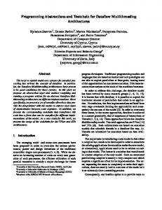
V. INDOOR SHADOWING MODEL For simulation of, e.g., industrial wireless networking applications, an indoor propagation model of radio signals is required. The PiccSIM Toolchain is complemented with such a modeling tool. The ns-2 simulator is extended with an indoor propagation model, which calculates the shadowing from walls. This extension makes more realistic indoor simulations, such as building automation scenarios [8], than the default ns-2 propagation models, since the attenuation of the actual walls is taken into account. Modeling signal propagation in indoor environments is more difficult than outdoor modeling. During propagation inside a building, radio waves encounter various obstacles leading to shadowing and multiple propagation paths. This makes the accurate modeling of signal propagation quite hard. Some measurements have been done in industrial environments in [3] and with sensor nodes in [15]. Network simulators, such as ns-2, use statistical propagation models to emulate signal attenuation, which focus on calculation of average path loss. Owing to straightforward formulas, these empirical models are easy and fast to apply, but do not take the environment into account. The purpose of the indoor shadowing extension is to create a simple model, which calculates the wall attenuations. Due to its simplicity, it can easily be added to existing, more complicated models, enabling more accurate results. The Multi-Wall Model, which is used here, takes into account the walls located directly between the transmitter and the receiver and the individual material properties [16]. The calculation of wall attenuations requires quite an accurate description of the indoor scenario and selection of proper path loss exponent is crucial, because the value is highly dependent on the type of building or structure of the indoor environment. In an office environment with walls and furniture, the value is usually between 3 and 6. The wall attenuation values of the extension are selected based on statistical results from measurements. The simulator takes a simplified grayscale picture of the environment, the building blueprint, as an input. This picture portrays different wall materials with different colors. The corresponding attenuation factors are defined for each color in a table. The simulator calculates the attenuation of the transmitted power in every pixel in the given blueprint. The losses due to walls are added to the overall path loss. Fig. 7 illustrates the coverage prediction of the simulator and a comparison to actual measurements. About 75 % of the simulated values differ from the real values less than 7.5 dB. The advantage of the model is that it is easily expandable to include frequency dependent fading and body shadowing.
-5 -10
-60 dB
-15
-54 dB
-20
-48 dB
-25
Fig. 7. Coverage prediction (left) and error compared to measurements (right) in dB.
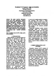
Shadowing objects introduce variation to the real values. The simulator takes this effect into account using a lognormal distribution in addition to the calculated fading. VI. EXAMPLE CASE A brief example is given here to demonstrate the modeling, simulation and automatic code generation capabilities of the PiccSIM Toolchain. A laboratory scale trolley crane system with an ultrasound based measurement system to measure the swing of the load is used as a testbed [17]. Previously, the swing was compensated with a wired control system using a fuzzy logic controller. The system also includes a Kalman filter to estimate the load angle when the ultrasound measurement system is unable to calculate it. The Kalman filter and a simple anti-swing controller are modeled with the generic node blocks of the Toolchain. The corresponding PiccSIM radio blocks are added to enable wireless communication between the nodes. The process to be controlled is modeled as a simple pendulum and attached to a generic node block functioning as an interface node to the trolley crane. The interface node samples the process with an analog input and sends the measurement to the angle estimation node (Kalman filter). The Kalman filter node estimates the current load angle and angle velocity, and sends them to the controller node. The controller is a PD controller, which uses the received estimates to calculate an appropriate control signal to stop the load swing. Upon reception of the control value from the controller node, the interface node outputs it via the DAC. The whole simulation model is shown in Fig. 8. The system is implemented in the PiccSIM Toolchain and the controller is tuned by simulation. When the results are approved, the interface, Kalman filter and controller blocks are converted into C-code using the automatic code generation feature of the Toolchain, and downloaded to the Sensinode wireless nodes. The interface node is connected to the trolley crane system for reading the load angle and writing the trolley swing compensation control signal. The whole system is run, and the anti-swing result is shown in Fig. 9. This demonstrates that a wireless control system designed in simulations can be automatically implemented on actual wireless nodes with the PiccSIM Toolchain. The code is efficient enough to run a two-state Kalman filter, ten times a second, to estimate the load angle and velocity. 53
Authorized licensed use limited to: Baylor University. Downloaded on March 01,2010 at 15:10:00 EST from IEEE Xplore. Restrictions apply.
Radio timestamp 1
Some improvements to the PiccSIM simulator, such as Simulink - ns-2 simulator synchronization and indoor radio propagation model are presented. The workflow from modeling and design to simulation and implementation on real wireless network nodes is presented to demonstrate the features of the Toolchain. Future work includes comparison between the simulation and the functionality of the generated code to assess the validity of the simulation results and the efficiency and calculation capabilities of the nodes for control applications.
Radio trigger 1
Radio timestamp 1 Radio send 1
Radio recv 1
Radio send 1
Radio recv 1
Pendulum _controller
Kalman _filter
Send to N 0 T 3
Timestamps
Timestamps
Node
Node Send to N 2 T 2
ID = 2
ID = 1 Data N 1 T 2
Data N 0 T 1
Send enable
Node _Controller
Node _ KF
Process Process AD 0
DA 6
Radio timestamp 1
DA 7
VIII. REFERENCES [1]
Stop bit Radio send 1
Radio recv 1
Process_interface
do { ... } while Synchronize with Ns -2
[2]
Timestam ps
Node Send to N 1 T 1 u
ID = 0 Data N 2 T 3
[3]
Interface node
Fig. 8. Simulink simulation model for trolley swing estimation and control system with wireless nodes. Signal flow indicated. 50
[4]
1
[5]
Load angle Anti-swing Control
0
0
Anti-swing Control [Nm]
Load angle [°]
[6]
[7] [8]
[9]
-50 40
45
50 Time [s]
55
-1 60
[10]
Fig. 9. Anti-swing test run with wireless nodes, angle of load and anti-swing control signal shown. Start of anti-swing indicated.
[11]
VII. CONCLUSIONS
[12]
The PiccSIM Toolchain is a complete toolset for NCS design, modeling and implementation. It is based on a cosimulation platform where the plant/environment and control algorithms are simulated in Simulink, and the network in ns-2. It is suitable for any wireless distributed application, including NCS and sensor network application simulation. The Toolchain contains interfaces for network and controller design and a main GUI for running simulations. It also supports automatic code generation from Simulink to wireless sensor nodes. Any algorithm can be designed with the generic node block of the Toolchain. This enables implementing simulated algorithms or a Simulink block diagram on real wireless sensor node hardware.
[13] [14] [15] [16] [17]
G.W. Irwin, J. Colandairaj, and W.G. Scanlon, “An Overview of Wireless Networks in Control and Monitoring,” in Proc. International Conference on Intelligent Computing (ICIC), Kunming, China, Aug. 16-19, 2006. A. Willig, K. Matheus, and A. Wolisz, “Wireless Technology in Industrial Networks,” Proceedings of the IEEE, vol. 93, iss. 6, Jun. 2005, pp. 1130-1151. Willig and R. Mitschke, “Result of bit error measurements with sensor nodes and casuistic consequences for the design of energy-efficient error control schemes,” in Proc. European Conference on Wireless Sensor Networks, Zurich, Switzerland, 2006. Y. Tipsuwan and M.-Y. Chow, “Control methodologies in networked control systems,” Control Engineering Practice, vol. 11, 2003. A. Al-Hammouri, D. Agrawal, V. Liberatore, H. Al-Omari, Z. AlQudah, and M. S. Branicky, “Demo abstract: a co-simulation platform for actuator networks,” Sensys, 2007. S. Nethi, M. Pohjola, L. Eriksson, and R. Jäntti, ”Platform for Emulating Networked Control Systems in Laboratory Environments,” in Proc. 8th International Symposium on a World of Wireless, Mobile and Multimedia Networks, Helsinki, Finland, Jun. 18-21, 2007. ns-2, “The Network Simulator,” http://www.isi.edu/nsnam/ns/. S. Nethi, M. Pohjola, L. Eriksson, and R. Jäntti, “Simulation case studies of wireless networked control systems,” in Proc. 10th ACM/IEEE International Symposium on Modelling, Analysis and Simulation of Wireless and Mobile Systems, Crete, Greece, Oct. 2007. M. Pohjola, S. Nethi, and R. Jäntti, “Wireless control of mobile robot squad with link failure,” in Proc. First Workshop on Wireless Multihop Communications in Networked Robotics, Berlin, Germany, Apr. 4, 2008. M. S. Hasan, H. Yu, A. Griffiths, and T.C. Yang, “Co-simulation framework for Networked Control Systems over multi-hop mobile adhoc networks,” in Proc. 17th International Federation of Automatic Control World Congress, Seoul, Korea, Jul. 6-11, 2008. L. Eriksson and T. Oksanen, ”PID Controller Tuning for Integrating Processes: Analysis and New Design Approach,” in Proc. 4th International Symposium on Mechatronics and its Applications, Sharjah, UAE, Mar. 2007. K. J. Åström and T. Hägglund, “Revisiting the Ziegler-Nichols step response method for PID control,” Journal of Process Control, vol. 14, pp. 635-650, Sept. 2004. D. Mahrenholz and S. Ivanov, “Real-time network emulation with ns2,” in Proc. Eighth IEEE International Symposium on Distributed Simulation and Real-Time Applications, Oct. 21-23, 2004, pp. 29- 36. Sensinode Ltd., [Online]. http://www.sensinode.com/. S. Kjesbu and T. Brunsvik, “Radiowave propagation in industrial environments,” in Proc. 26th Annual Conference of the IEEE Industrial Electronics Society, vol. 4, Nagoya, Japan, Oct. 2000. W. K. Tam and V. N. Tran, “Propagation modelling for indoor wireless communication,” Electronics & Communication Engineering Journal, vol. 7, oo. 5, pp. 221-228, Oct. 1995. L. Eriksson, V. Hölttä, and M. Misol, “Modeling, simulation and control of a laboratory-scale trolley crane system,” in Proc. The 47th Conference on Simulation and Modelling, Helsinki, Finland, Sept. 2829, 2006. H
H
54 Authorized licensed use limited to: Baylor University. Downloaded on March 01,2010 at 15:10:00 EST from IEEE Xplore. Restrictions apply.
H