prédicat(s) sur leurs propriétés ou sur existence d'une association (directe ou ..... prédicat de jointure du type (R.a=S.b) sous-entend que R.a et S.b varient sur le ...
N° d'ordre : _____
Université de Versailles Saint-Quentin-en-Yvelines THÈSE / PhD THESIS Pour obtenir le grade de docteur
discipline : Informatique présentée et soutenue publiquement par Nicolas ANCIAUX Le 17 décembre 2004 Sur le sujet
Systèmes de gestion de base de données embarqués dans une puce électronique (Database Systems on Chip) ________
JURY Professeur Philippe PUCHERAL, Directeur de thèse Professeur Michael J. FRANKLIN, Rapporteur Professeur Patrick VALDURIEZ, Rapporteur Docteur Philippe BONNET, Examinateur Docteur Luc BOUGANIM, Examinateur Monsieur Jean-Claude MARCHETAUX, Examinateur
à Ani, à M’An, Sèv, Angel et Garooj…
-i-
Remerciements – Acknoledgements
Merci d'abord à Benoît sans qui cette thèse n’aurait pas vu le jour sans, vu que je n’aurais jamais découvert l’informatique. J’y pense chaque matin que fait le calendrier. Merci aussi énormément à Miflo sans qui non plus je n’aurais pu vivre ces quelques mois qui m’ont procuré ces années de plaisir. Et merci aussi à M’An et Vincent, qui m’ont poussé et aidé dans mon parcours lorsqu’il était pénible, et sans qui je n’aurais pu passer ces 4 ans de plaisir. Re-Merci encore, Luc, pour avoir su me motiver, supporter mes égarements durant ces 4 années, et surtout pour ces moments de recherche excitants et agréables. Je voudrais revivre aussi ces instants de sud, de conférence rigolard, et de trajets en moto. Merci surtout pour cet encadrement génial et tout le temps que tu m’as donné et pour ton amitié. Merci Philippe, pour savoir recarder le travail sans jamais décourager, pour m’avoir accueilli en DEA et m’avoir ouvert les portes de l’équipe formidable que tu as su construire à l'INRIA, pour ta façon de voir les problèmes simplement et avec rigueur même sans couleur. Merci à toi comme à Luc pour avoir rendu aussi impérissables et joyeux le souvenir qui me reste de ces années de thèse, et tes conseils de vie aussi. Merci aussi à Jean-Claude Marchetaux, pour tes compétences et ta patience, et pour tes explications précieuses. Mes contacts avec toi m'ont beaucoup apportés et m'ont donné une jolie image du monde de l'entreprise. Merci aussi pour le temps que tu as passé sur PicoDBMS. Sans toi et Alain Boudou nous n'aurions pu produire ce travail. Thank you very much to Mike Franklin and Patrick Valduriez for reading this work during a very busy period. Someone told me that PhD reports, in average, are read by two or three people in addition to their author. Your are the first two of these people in reading my document, and it is a great honor already. Merci à Georges Gardarin et Patrick pour votre soutient, qui me permet d'envisager encore de nombreuses années de recherches. J'espère prendre autant de plaisir que j'en ai pris ici dans la suite. Merci aussi à Chantal Ducoin qui m'a administrativement sauvé la mise plusieurs fois ! Merci Aussi à Christophe et Saida pour ces instants de cohabitation dans notre bureau du PRiSM. Merci aussi Philippe, Luc, Thierry, Béatrice et Zoubida pour vos précieux
-ii-
conseils de préparation de cours et de TD. Merci à tous ceux avec qui nous avons passé ces petits moments de détente entre cigarettes et machine à café, Jean-Pierre, François, Sophie, Lilan, Christian et Aurélian. Merci à Minère, Dods, Maia, Marion, Jacky, Dji-Luc, et à toute la famille, d'avoir entrepris pour certain un si long voyage pour être présent à la soutenance, et merci à mes beaux-parents, Angel et Garooj, qui sont parfois passés en France ces derniers temps et ont du dormir avec la lumière de l'ordinateur allumé. Et enfin, merci Anaenza d'avoir pu te libérer pour ma soutenance, et merci pour les fous-rires, pour ta voix joyeuse, et pour ton amour pour les excès et les passions en tout genre, merci pour ton amitié.
Nicolas Anciaux
-iii-
Table of Content
Chapter 1 – Introduction ........................................................................... 1 1
Context of the study........................................................................................... 2
2
Addressed Issues................................................................................................ 3
3
Contributions ..................................................................................................... 5
4
Prototypes .......................................................................................................... 7
5
Outline ............................................................................................................... 7
Chapter 2 – Smart Card, Databases and Cryptography Background........ 9 1
Smart Card Technology ..................................................................................... 9 1.1 1.2
2
DBMS Techniques........................................................................................... 28 2.1 2.2 2.3 2.4 2.5
3
Smart Cards Computing Environment ..............................................................................10 Smart Card Hardware Resources ......................................................................................21 Impact of Data Storage Medium on Query Processing.....................................................29 Data Layouts .....................................................................................................................30 Access Methods ................................................................................................................31 Operators Library and Execution Model...........................................................................35 Optimization .....................................................................................................................37
Cryptography ................................................................................................... 38 3.1 3.2
Data Encryption ................................................................................................................39 Authentication and Integrity .............................................................................................44
Chapter 3 – Query Processing in a RAM Constrained Environment ..... 49 1
Introduction...................................................................................................... 49
2
Context of the Study ........................................................................................ 52
3
RAM Lower Bound Query Execution Model.................................................. 53 3.1 3.2 3.3
4
Design Rules and Consistency Constraints.......................................................................53 Execution Model and Notations........................................................................................54 Operator’s Algorithms ......................................................................................................55
Optimizations in RAM Lower Bound ............................................................. 59 4.1 4.2
Minimizing Required Tuples ............................................................................................61 Eager Pruning of Irrelevant Tuples ...................................................................................62
-iv-
4.3 4.4
5
The Impact of RAM Incremental Growths...................................................... 64 5.1 5.2
6
Impact on the Operator’s Algorithms ...............................................................................64 Impact on Iteration Filters.................................................................................................66
Performance Evaluation................................................................................... 67 6.1 6.2 6.3
7
Expressing Iteration Filters ...............................................................................................63 Checking Iteration Filters..................................................................................................63
Experimentation Platform .................................................................................................67 Data, Queries and Experiments.........................................................................................68 Interpretation of the Results..............................................................................................68
Conclusion ....................................................................................................... 72
Chapter 4 – PicoDBMS Study ................................................................ 75 1
Introduction...................................................................................................... 75
2
Problem Statement........................................................................................... 76
3
Related Works.................................................................................................. 78
4
PicoDBMS at a Glance .................................................................................... 80 4.1 4.2 4.3
5
Performance Evaluation and Lessons Learned................................................ 89 5.1 5.2 5.3 5.4
6
Storage and Indexation .....................................................................................................81 Query Processing ..............................................................................................................84 Transaction Processing .....................................................................................................87 Objective and Performance Metrics..................................................................................89 PicoDBMS Kernel Footprint ............................................................................................90 Database Footprint ............................................................................................................91 PicoDBMS Performance...................................................................................................93
Conclusive Remarks and Case Studies.......................................................... 104
Chapter 5 – Coping with Storage Limitation for Smart Card RDBMS 109 1
Introduction.................................................................................................... 109
2
Related Works................................................................................................ 110
3
Problem Formulation ..................................................................................... 111 3.1 3.2 3.3 3.4
4
Reference Architecture ...................................................................................................111 Attacks ............................................................................................................................113 Security Objectives .........................................................................................................114 Problem Statement ..........................................................................................................114
Proposed Approach........................................................................................ 115 4.1
Architectural Dimension .................................................................................................115
-v-
4.2
5
Cryptographic Techniques............................................................................. 117 5.1 5.2 5.3 5.4 5.5
6
Data Snooping.................................................................................................................118 Data Altering...................................................................................................................118 Data Substituting and Data Replaying ............................................................................120 Timestamps Storage........................................................................................................121 Preliminary discussion on costs ......................................................................................122
Query Processing ........................................................................................... 124 6.1 6.2 6.3
7
Cryptographic and Query Processing Dimension ...........................................................116
Execution Basics, Notations and Assumptions ...............................................................124 Select-Project-Join Queries.............................................................................................125 Group By and Aggregation Operations...........................................................................129
Conclusion and Future Works ....................................................................... 130
Chapter 6 – Conclusion and Research Perspectives ............................. 133 1
Summary........................................................................................................ 133
2
Research Perspectives.................................................................................... 135
Résumé en Français – French Summary............................................... 139 1
Introduction.................................................................................................... 139 1.1 1.2 1.3
2
Bases de Données Sécurisées dans une Puce................................................. 143 2.1 2.2 2.3 2.4
3
Evolution des Technologies et des Usages .....................................................................143 Exemples d'Applications.................................................................................................144 Formulation du Problème................................................................................................146 Travaux Existant .............................................................................................................149
Le SGBD Embarqué PicoDBMS................................................................... 151 3.1 3.2 3.3
4
Contexte de l'Etude .........................................................................................................140 Contributions de la Thèse ...............................................................................................141 Organisation du Résumé .................................................................................................142
Modèle de Stockage et d'Indexation ...............................................................................152 Exécution de Requêtes ....................................................................................................154 Aspects Transactionnels..................................................................................................156
Mesures de Performances et Enseignements ................................................. 158 4.1 4.2 4.3 4.4 4.5
Objectif et Métrique des Evaluations..............................................................................158 Empreinte du Code .........................................................................................................159 Empreinte des Données...................................................................................................160 Performances de PicoDBMS ..........................................................................................161 Conclusion et Etudes de Cas...........................................................................................172
-vi-
5
Perspectives de Recherche............................................................................. 174 5.1 5.2
6
Calibrage de la Quantité de Mémoire Volatile................................................................177 Délégation de Ressources ...............................................................................................180
Conclusion ..................................................................................................... 183
References ............................................................................................. 185
-vii-
List of Figures
Figure 1 Figure 2 Figure 3 Figure 4 Figure 5 Figure 6 Figure 7 Figure 8 Figure 9 Figure 10 Figure 11 Figure 12 Figure 13 Figure 14 Figure 15 Figure 16 Figure 17 Figure 18 Figure 19 Figure 20 Figure 21 Figure 22 Figure 23 Figure 24 Figure 25 Figure 26 Figure 27 Figure 28 Figure 29 Figure 30 Figure 31 Figure 32 Figure 33 Figure 34
Smart Cards Shipments. ......................................................................................... 9 Smart Card’s Normalized Formats (ISO and GSM). ........................................... 11 Data Transmission between Smart Card and User............................................... 12 Embedded Chip Dimension (ISO). ...................................................................... 13 Smart card’s Contacts (ISO). ............................................................................... 14 Smart Card’s Architecture.................................................................................... 22 Evolution of Smart Card Prototypes Architecture. .............................................. 27 Query Processing Architecture. ........................................................................... 28 Database Storage Models..................................................................................... 31 B-Tree. ................................................................................................................. 32 T-Tree................................................................................................................... 33 Hash Based Structures.......................................................................................... 34 Join Indices. ......................................................................................................... 34 DBGraph Possible Implementation for Efficient Joins........................................ 34 A Sample QEP. .................................................................................................... 36 Hash Join Iterator [Gra93]. .................................................................................. 37 Sample QEP Processing Using the Iterator Model. ............................................. 37 Different Tree Shapes of the Same Query. .......................................................... 38 Electronic CodeBook (ECB) Encryption. ............................................................ 40 ECB Mode Opacity.............................................................................................. 41 Cipher Block Chaining (CBC) Encryption. ......................................................... 41 CBC Mode Opacity.............................................................................................. 42 Counter Mode (CTR). .......................................................................................... 42 Triple DES. .......................................................................................................... 43 C ANSI Comparative Performance on Pentium [Nes01, Nes03]. ....................... 45 MDC Based Integrity. .......................................................................................... 46 MAC Based Integrity. .......................................................................................... 48 Query Example and Notations. ............................................................................ 55 RLB Algorithms................................................................................................... 56 Snapshot of the Three GroupBy Algorithms........................................................ 58 Iterations Performed by a RLB Query Evaluator................................................. 60 Group Filters. ....................................................................................................... 64 Buffered Sort........................................................................................................ 66 Evaluation Results................................................................................................ 71
-viii-
Figure 35 Figure 36 Figure 37 Figure 38 Figure 39 Figure 40 Figure 41 Figure 42 Figure 43 Figure 44 Figure 45 Figure 46 Figure 47 Figure 48 Figure 49 Figure 50 Figure 51 Figure 52 Figure 53 Figure 54 Figure 55 Figure 56 Figure 57 Figure 58 Figure 59 Figure 60 Figure 61 Figure 62 Figure 63 Figure 64 Figure 65 Figure 66 Figure 67 Figure 68 Figure 69 Figure 70 Figure 71 Figure 72 Figure 73 Figure 74
PicoDBMS Architecture. ..................................................................................... 81 Domain Storage.................................................................................................... 82 Ring Storage......................................................................................................... 83 Several Execution Trees for Query Q1:'Who prescribed antibiotics in 1999 ?'... 85 Four ‘Complex’ Query Execution Plans. ............................................................. 87 PicoDBMS Code Footprint. ................................................................................. 91 Medical Database Schema. .................................................................................. 92 PicoDBMS Storable Tuples. ................................................................................ 92 Smart Card Simulation Platform.......................................................................... 94 Synthetic Database Schema. ................................................................................ 94 Performance of Insertions. ................................................................................... 97 Projection Transmission Rate. ............................................................................. 98 Selection Queries Transmission Rate (SP). ......................................................... 99 Pure Join Queries Transmission Rate. ............................................................... 100 SPJ and SPJn Queries Transmission Rate. ......................................................... 101 Transmission Rate of Aggregation Queries (SPG, SPJG, SPJGn). ..................... 103 Reference Architecture....................................................................................... 111 Architecture Instantiations. ................................................................................ 112 PDUs Generation Process. ................................................................................. 121 Memory Partitioning into Freshness Blocks and Pages. .................................... 122 Query Execution Plan P1.................................................................................... 126 Query Execution Plan P2.................................................................................... 127 Sort Merge Join Process..................................................................................... 128 Query Execution Plan P3.................................................................................... 129 PAX as a Storage Model Example..................................................................... 131 Storage Example for Join Indices. ..................................................................... 132 Architecture de PicoDBMS................................................................................ 151 Stockage en domaine. ........................................................................................ 153 Stockage en anneau. ........................................................................................... 154 Plan d’exécution de requêtes complexes............................................................ 155 Taille du code de PicoDBMS............................................................................ 160 Schéma de la base de données. .......................................................................... 161 Capacité de Stockage de PicoDBMS. ................................................................ 161 Plate-forme de simulation de carte à puce ......................................................... 162 Schéma de base de données synthétique. ........................................................... 163 Performances d’insertion. .................................................................................. 165 Performance des requêtes de projection (P)....................................................... 167 Performances des requêtes de sélection (SP). .................................................... 168 Performances des requêtes de jointures pures.................................................... 169 Performance des requêtes de jointure avec sélection (SPJ, SPJn). ..................... 170
-ix-
Figure 75 Figure 76 Figure 77 Figure 78 Figure 79 Figure 80
Performances des requêtes d'agrégation (SPG, SPJG, SPJGn)........................... 171 Requête exemple et Dflow. ................................................................................ 178 Algorithme GroupBy. ........................................................................................ 178 Itérations nécessaires à l’évaluation à consommation minimale........................ 179 Filtres d'itération de l'algorithme de groupement............................................... 179 Architecture de référence. .................................................................................. 181
-x-
List of Tables
Table 1 Table 2 Table 3 Table 4 Table 5 Table 6 Table 7 Table 8 Table 9 Table 10 Table 11 Table 12 Table 13 Table 14 Table 15 Table 16 Table 17 Table 18 Table 19 Table 20 Table 21
Typical Application’s Profiles. ............................................................................ 18 Memory Cell Relative Size. ................................................................................. 24 Embedded Memory Density. ............................................................................... 24 Current Smart Cards Products.............................................................................. 25 Next Generation of Cards (coarse-grain FLASH)................................................ 25 Next Generation of Cards (fine-grain FLASH or EEPROM). ............................. 26 Performance of Stable Memory. .......................................................................... 26 Long Term Memory Alternatives. ....................................................................... 27 Description of Access Rights on Embedded Data. .............................................. 77 Schema of Relation R0. ........................................................................................ 95 Query Set for the Performance Evaluation. ......................................................... 96 Transmission Rate Ratios................................................................................... 104 Percentage of the Total Result Produced in 1 Second. ...................................... 105 Number of Results Tuples Produced in 1 Second.............................................. 106 Profiles des applications des cartes à puce......................................................... 146 Description des Droits d'Accès sur les Données Embarquées. .......................... 148 Schéma de la Relation R0................................................................................... 164 Jeu de requêtes des évaluations de performance. ............................................... 164 Rapports des taux de transmission. .................................................................... 172 Pourcentage de tuples du résultat transférés en 1 seconde................................. 173 Nombre de tuples minimal transférés par seconde............................................. 174
-xi-
-xii-
Database on Chip
Chapter 1 – Introduction
Chapter 1 – Introduction
We are moving towards the third wave of computing, in which a large number of specialized computing devices will be everywhere, serving everybody. Mark Weiser, the pioneer of ubiquitous computing, was the first to paint this vision in the early 1990s [Wei91]. He defined ubiquitous computing as the opposite of virtual reality: “Where virtual reality puts people inside a computer-generated world, ubiquitous computing forces the computer to live out here in the world with people.” In this vision, people are surrounded by an electronic environment made of a proliferation of smart objects. The smart objects composing this environment would be aware of people’s presence and needs, and could adjust their actions in consequence. The concept of smart object appears in the middle of the 1990s, at the crossroad between component miniaturization, information processing technologies and wireless communications. We see smart objects as chips endowed with data acquisition, data storage, data processing, and communication abilities. Examples are smart cards (Java multi-application cards, banking cards, SIM cards for cell phones, identification cards etc.), sensors monitoring their environment (gathering weather, pollution, traffic information, etc.), embedded chips in domestic appliances [BID+99, KOA+99, Wei96] (e.g., embedded chip in a set top box). Medicine researchers also expect chips (e.g., Smartdust [KKP]) to be ingested or inhaled (e.g., to monitor sugar rate in blood and automate its regulation for diabetics). Since smart objects acquire and process data, the need for embedded database techniques arises. For instance, in [BGS01], networks of sensors collecting environmental data are compared to distributed databases, each sensor acting as a micro-data server answering queries. [MaF02] brought out the need for executing local computation on the data, such as aggregation in push-based systems, in order to save communications and thereby power consumption. Local computation is also required to participate in distributed pull-based queries [MFH+02]. Also, protecting the confidentiality of collected contextual data or portable folders (e.g., healthcare folders, phone and address books, agendas) stored in secure smart objects leads to embed sophisticated query engines to prevent any information disclosure [PBV+01]. These examples are representative of the increasing need for embedding more and more database functionalities in smart objects. This manuscript focuses on the impact of smart objects’ hardware constraints on
-1-
Database on Chip
Chapter 1 – Introduction
embedded database techniques. The first section highlights these hardware constraints and motivates the need for embedding database components in small devices. Section 2 presents the main issues addressed during the thesis. Section 3 summarizes the three main contributions developed in this document. Section 4 briefly presents the prototypes implemented to assess the different contributions of this thesis. Finally, Section 4 gives the outline of the manuscript.
1
Context of the study
This section describes the constrained computing environment of smart objects and motivates the need for embedding database components in smart objects. Smart objects have highly constrained resources due to technical and economical motives. Smart objects have to be physically small. Indeed, several application domains require smart objects to be small enough to be embedded (e.g., in domestic appliance), disseminated (e.g., sensors), portable (e.g., smart cards), ingested (e.g., medical applications), etc. This reduced size obviously impacts the available resources notably in terms of stable storage capacity and RAM size. Moreover, many smart objects are autonomous, and then energy considerations conduct also to limit the resources notably in terms of CPU speed and communication bandwidth. Security exacerbates the previous concerns, the chip size (e.g., in smart cards) being reduced to render the cost of attacks prohibitive and to avoid tampering by monitoring the chip activities (e.g., monitoring the data bus). Finally, economical considerations lead to reduce the production cost of massmarket appliances to their minimum. For a given fabrication process (e.g., 0.18 micron), the cost of the chip is directly linked to its size, therefore on-board resources must be carefully calibrated. Designing embedded database components for smart objects is an important issue [ABP03c] for the three following reasons: Smart objects may collect or store information related to individuals, thus leading to privacy preservation concerns. As soon as the confidentiality of the acquired data is a concern1, the query processing must remain confined in the smart object to build and deliver only the authorized subpart of the embedded data. In that case, the complexity of the embedded query engine depends on the sophistication of the access rights. In the future aware environment [BID+99, KOA+99], many programs and physical users may interact with disseminated smart objects, each one with specific access rights. Saving communication costs represents another motivation for embedding database components. Indeed, in a wireless context, energy consumption is directly linked to the amount of transferred data. Therefore, database filtering and aggregation facilities, and more
-2-
Database on Chip
Chapter 1 – Introduction
generally any database functions allowing the reduction of transmitted data, are indispensable partners of smart objects. Since communication savings allow reducing energy consumption [MFH+03], this motivation will remain valid for a while. Finally, embedded data management techniques are required in every context where computations have to be performed in a disconnected mode. For example, smart objects embedded in a human body to monitor the cardiac pulse and rapidly liberate chemical medication in case of abnormal activity, must process the data locally without relying on any remote operation. Therefore, confidentiality, communication and thus energy saving, and disconnected activities are three motivations for embedding database components in smart-objects. The design of embedded database components for smart objects is thus an important problem. This problem is complicated given that each architecture exhibits specific properties (e.g., energy consumption, tamper resistance) as well as specific hardware constraints (e.g., bounded silicon's die size, hardware resources asymmetry).
2
Addressed Issues
This dissertation focuses on three different and complementary facets of the above problem. The first issue addressed is the RAM consumption problem in the design of database components embedded on chips. This study is motivated by the fact that the RAM turns to be the most limiting factor in a smart object context. The second and third issues addressed are more specifically related to the smart card environment, the today’s most widespread and secure representative of smart objects. More precisely, our second study capitalizes on the PicoDBMS study [PBV+01] to develop and assess processing techniques for evaluating authorized database views in a smart card. Finally, our third study proposes to bypass the storage limitation of the smart card by using remote - but insecure - storage space. The unifying thread of these three studies is the query evaluation problem in hardwareconstrained environment. We discuss below the motivation of each of these three studies. RAM-constrained query processing techniques: Although the computing power of lightweight devices globally evolves according to Moore’s law, the discrepancy between RAM capacity and the other resources, notably CPU speed and stable storage capacity, still increases. This trade-off is recurrent each time the chip’s size needs be reduced to match the aforementioned constraints such as thinness, energy consumption, tamper resistance or production costs on large-scale markets. In addition, the large size of RAM cells compared with stable memory cells (16 times larger than ROM cells) makes matters worse. Since the RAM is highly reduced, strategies to overcome main memory overflows must be found. However, query evaluation techniques cannot rely on swapping, as in traditional DBMSs, for 1 Even ordinary data may become sensitive once grouped and well organized in databases.
-3-
Database on Chip
Chapter 1 – Introduction
several reasons. First, smart objects use commonly electronic stable memory like EE-PROM or Flash memory. Although these technologies provide compactness (small cell size), reduced energy consumption and production costs, their writing costs are extremely high (up to 10 ms per word in EE-PROM) and the memory cell lifetime is limited to about 105 write cycles. Second, a swapping area would compete with the area devoted to the on-board persistent data and there is no way to bound it accurately. Obviously, if we assume that external resources can be exploited, the RAM problem vanishes. But, as stated previously, communication costs, data confidentiality and disconnected activities lead to the execution of on-board queries. As a conclusion, RAM will remain the critical resource in most smart object environments and the ability to calibrate it against data management requirements turns out to be a major challenge. Query processing techniques for smart card databases: Smart card is today the most widely represented smart object (roughly two billion smart cards are produced annually). Moreover, smart card is considered as the most secure computing device today and is thus used in many applications exhibiting high security requirements such as banking, cellular phone, identification, and healthcare. In data centric smart card applications (e.g., personal folder on chip), confidential data reside inside the chip, and thus benefit from the smart card tamper resistance. However, this forces to embed a specific code in the chip, which authenticates the users and solely delivers the data corresponding to their access rights (i.e., authorized database views). A trivial solution to this problem could be to embed a file system and to materialize each authorized database view in a separate file. However, this solution badly adapts to data and access right updates and results in a huge data replication among files, hurting the smart card storage constraint. Thus, a dynamic evaluation of the authorized views is highly required. To this end, ad-hoc query evaluation techniques matching the strong smart card hardware constraints have to be devised. Current powerful smart cards are endowed with 64 kilobytes of stable storage (EEPROM), 4 kilobytes of random access memory (RAM) from which only hundreds of bytes are available for the applications (most of the embedded RAM is reserved for the operating system), and 96 kilobytes of read-only memory (ROM) holding the operating system and possibly a Java virtual machine. These smart cards are equipped with CPU powerful enough to sustain cryptographic operations (typically 32 bits CPU running at 50MHZ). Such hardware architectures exhibit an untraditional balance in terms of storage and computing resources. First, the discrepancy between stable storage reads and writes is untraditional since reads are random and very fast (comparable to RAM reads), while write latency is very high (several ms/word). Second, the CPU processing power is oversized compared to the on-board amount of persistent data. Furthermore, smart cards are not autonomous, i.e., they have no independent power supply, which precludes asynchronous and/or disconnected processing. Thus, the definition and assessment of query processing techniques dedicated to existing and future smart card platforms are highly required. Tamper-resistant query processing techniques for external data: Given the smartcard
-4-
Database on Chip
Chapter 1 – Introduction
tiny die size, the amount of stable storage will remain limited to few megabytes for a while. Indeed, new stable memory technologies (e.g., micro- and nanomechanical technology [VGD+02]) are not expected to be available soon. An interesting challenge is therefore to use remote resources to increase smart cards abilities. Since smart cards are plugged into or linked to a more powerful device (e.g., PC, PDA, cellular phone), the objective is to take advantage of the device's storage capabilities to overcome the smart card limitations. This proposal is particularly well suited to emerging smart card based architecture where a secure smart card chip is connected to large but insecure memory modules. For instance, the Gemplus’ SUMO "smart card" provides 224 megabytes of FLASH memory dispatched within the plastic's substrate. Another example is the MOPASS consortium [MOP04], which proposes to combine FLASH memory cards with a smart card. However, the issue is to use remote resources without losing the smart card benefits, i.e., the high level of security provided to the data. Since the data is stored remotely in an insecure environment, its confidentiality can be violated and its contents can be altered (even if encrypted). This motivates the study of query processing techniques that allow to externalizing persistent (and intermediate) data on an insecure remote storage while keeping the same tamper-resistance as smart card databases.
3
Contributions
As noted earlier, smart objects hardware configurations are more and more specialized to cope with specific requirements in terms of lightness, battery life, security and production cost. Building an ad-hoc query evaluator for each of them will rapidly become cumbersome and, above all, will incur a prohibitive design cost. Thus, there is a clear need for defining pre-designed and portable database components that can be rapidly integrated in smart objects. The different studies conducted in this thesis typically address this requirement. We summarize below our contributions related to the three research issues highlighted in the preceding section. RAM constrained query processing techniques: we propose a framework for designing RAM-constrained query evaluators allowing to process SQL-like queries on on-board relational data. Our study follows a three-step approach. First, we devise a RAM lower bound query execution model by focusing on the algorithmic structure of each relational operator and on the way the dataflow must be organized between these operators. Second, we propose a new form of optimization to this lower bound execution model, called iteration filters. Iteration filters drastically reduce the prohibitive cost incurred by the previous model, without increasing its memory requirement. Finally, we study the impact of an incremental growth of RAM. We propose an adaptation of the previous execution techniques that best exploit each RAM incremental growth and we conduct a performance evaluation. We observe that very small RAM growths may lead to considerable performance gains and show that the proposed techniques constitute an accurate alternative to the index in a wide range of
-5-
Database on Chip
Chapter 1 – Introduction
situations. These evaluations allow proposing co-design guidelines helping to find the best compromise between RAM capacity, volume of on-board data, query complexity and response time. Query processing techniques for smart card databases: our second contribution deals with the management of complex access rights on embedded data, coping with the constraints of the smart card. This work capitalizes on the previous PicoDBMS study [PBV+01], which proposes to embed a full-fledged DBMS on a smart card in order to provide highly portable and secure database folders, with medical applications in mind. Our contribution is twofold. First, we categorize the different access rights requirements that may be defined on any kind of embedded data, with the objective to generalize the PicoDBMS approach. To this end, we define three main categories of authorizations, of increasing complexity, covering a wide range of situations: schema, occurrence and computed data authorizations. We then define seven access right types derived from these three categories that should be supported by a PicoDBMS-like system. Second, we make an in-depth performance evaluation: for each access right type, we measure the response time and/or the throughput when processing the corresponding authorized views (implementing the given access right). We investigate different storage and indexation alternatives and assess the effectiveness of each of them according to the amount of embedded data and to the access rights required by the application. The conclusions of this performance evaluation allow to decide which database technique/strategy should be embedded in a smart card with respect to a targeted - class of - application. Tamper-resistant query processing techniques for external data: our third contribution addresses the way to circumvent the smart card stable storage limitation using remote insecure storage. Since the data is stored remotely in an insecure environment, we use cryptographic techniques to ensure its confidentiality and its tamper-resistance. As opposed to several existing studies [HIL+02, BoP02, DDJ+03], we propose to reduce to a minimum the amount of processing that may be delegated to the device handling the insecure storage for three distinct reasons. First, the external device being insecure, the honesty of any processing done externally has to be checked afterward. Actually, such verification might be as expensive as the processing itself. Some techniques indeed exist for simple selections [GKM+04] but the problem remains open for more complex operations. Second, even if the preceding point could be solved, allowing processing on the encrypted data generally disclose some (fuzzy) information. Third, the external device considered may not have processing capabilities (e.g., SUMO, MOPASS). These reasons led us to consider the external storage as a file system delivering on requests encrypted data blocks. To increase performance, we show that each file should be divided in minimal data blocks and that each block should include its own tamper-resistance information. We then describe an adequate storage model relying strongly on encrypted indexes, and algorithms for processing queries in the smart card.
-6-
Database on Chip
4
Chapter 1 – Introduction
Prototypes
Three prototypes have been implemented in parallel to the studies conducted during this thesis. These three implementations are chronologically depicted in the following. A first prototype, called PicoDBMS, has been implemented during the year 2001, to study in practical the DBMS design proposal dedicated to the smart cards context envisioned in [PBV+01]. PicoDBMS has been build using the JavaCard language (subset of Java for smart cards) on a smart card prototype provided by Bull-CP8 (now Axalto, the smart card subsidiary of Schlumberger). The main objective of this implementation was to assess the feasibility of the full-fledge DBMS. However, performance measurements could not been conducted using this plate-form, due to the inadequate implementation of the on-board virtual machine in case of PicoDBMS like data centric applications (e.g., security controls increase each memory access by more thant 3 orders of magnitude, the RAM was totally disabled in the provided prototype precluding storing execution variables on the heap). A second prototype has been implemented during year 2002 to conduct the RAM aware query processing study. This study has been conducted considering flat data (no indices), a query execution engine based on repetitive access to the base data, and a small amount (bounded) of additional RAM available to materialize intermediate result. The context of this study (flat data, no indices, available RAM) and the envisioned optimization techniques (iteration filters) are highly different from the PicoDBMS prototype. Thus, a second prototype has been build on a PC, using the JavaCard language, to dump execution statistics into files used to give a response time based on a cost model calibrated with the smart card characteristics. The third prototype has been build during year 2003 and 2004 to measure the precise performance of PicoDBMS on an enhanced smart card prototype provided by Axalto, endowed with the native operating system Zeplatform (programmed in C Language). The PicoDBMS code available in JavaCard has been ported to C, and the operating system has been modified in partnership with Axalto to adapt to data centric applications. This prototype has been intensively studied to provide the performance measurements presented in Chapter 4. In parallel to this implementation on the real smart card, the code has been ported to a smart card hardware simulator (also provided by Axalto) that can be used for prospective measurements assuming future smart cards endowed with larger stable memories.
5
Outline
This study is at the crossroad of three domains: smart cards hardware architectures, data management techniques, and cryptography. The second chapter of this thesis gives the necessary background on these three domains in order to make the proposed contributions
-7-
Database on Chip
Chapter 1 – Introduction
understandable2. Chapter 3 focuses on embedded query processing in a RAM constrained environment and delivers co-design guidelines helping to find the best compromise between RAM capacity, volume of on-board data, query complexity and response time. Chapter 4 investigates different storage and indexation alternatives for smart card databases and assess the effectiveness of each of them according to the amount of embedded data and to the access rights required by a target smart card application. Chapter 5 investigates cryptographic and query processing techniques to make the management of data externalized in an insecure storage tamper-resistant. Finally, Chapter 6 concludes the document and opens up new research perspectives.
2 The background presented in each subsection (smart card, database and cryptography) can be
skipped by specialists of the corresponding area(s).
-8-
Database on Chip
Chapter 2 – Smart Card, Databases and Cryptography
Chapter 2 – Smart Card, Databases and Cryptography Background
The study conducted in this document is at the crossroad of three domains: smart card architecture, database query processing and cryptography. This chapter gives the needed prerequisites of theses area in order to make the proposed contributions understandable.
1
Smart Card Technology
A smart card is made of two main components: a plastic substrate (PVC or polyester resin) and a module, which contains a small integrated circuit. Its average price is between 50 cents and $4 [Kim04], depending on its internal complexity.
Shipments (millions of units)
2500 2000
Microprocessor card Memory card
1500 1000 500 0 1995 1999 2000 2001 2002 2003 2004
Figure 1
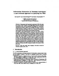
Smart Cards Shipments3.
Many manufacturers offer smart card products. The top five card manufacturers in volume of cards sales are Gemplus, Axalto (a Schlumberger subsidiary), Giesecke&Devrient, Oberthur, and Orga [Gar03]. The top ten smart card integrated circuit chip manufacturers are Infineon technology, ST Microelectronics, Philips Semiconductor, Atmel, Fujitsu, Hitachi, NEC, Samsung, Sony and Xicor [Mar03]. This is a very competitive 3 Source : Gartner Dataquest survey and www.eurosmart.com, May 2003.
-9-
Database on Chip
Chapter 2 – Smart Card, Databases and Cryptography
market, which introduces many product variants and innovations. Since 1999, more than 1.4 billion smart cards have been shipped each year, and this number will probably reach 2 billion this year (see Figure 1). Moreover, the share of microprocessor cards (the most elaborated type of smart cards) represents now more than half of the smart card market, compared to 25% four years ago. The current trend leads clearly to more powerful cards holding more data and programs and penetrating many domains including health care, loyalty, cellular phones, electronic payments, identity cards and driving licenses. Revenue generated by smart card sells reached $1.40 billion in 2003. In the future, analysts consider that smart cards will have an impact as big as the emergence of PCs [Sha02a] and revenue is expected to reach $2.38 billion by 20074. The following sections introduce some prerequisite knowledge required for an in-depth analysis of smart cards data management techniques. Section 1.1 describes the specific smart card environment while Section 1.2 depicts the unusual balance of resources in the on-board integrated circuit. The objective is to state the main difference between this constrained environment and traditional database ones. For an in-depth presentation of smart cards technology, we refer the reader to the IBM red book [IBM98], the smart card security and applications book [Hen01] and the U.S. government smart card handbook [Hol04].
1.1
Smart Cards Computing Environment
According to Webster [Web], a smart card is “a small plastic card that has a built-in microprocessor to store and process data and records”. However, this concept covers several devices, which are differentiated by both the capabilities of the on-board Integrated Circuit Chip (ICC) and by the interface used to communicate with the reader. Section 1.1.1 describes the different types of ICC while Section 1.1.2 focuses on the interface aspect. Section 1.1.3 enumerates the various ways one can use to break into a smart card and introduces the many security features developed to make smart cards tamper-resistant. Section 1.1.4 highlights recent initiatives to make smart cards an open platform. Current and future smart cards applications are presented in Section 1.1.5. Section 1.1.6 depicts future smart cards enhancements. In conclusion, Section 1.1.7 describes how the smart card unusual computing environment impacts the design of embedded database components.
1.1.1
Memory Card versus Smart Cards
There are two main types of chips that can be associated with cards: memory chips which are possibly enhanced with hard-wired procedures, and chips endowed with a microcontroller. Memory-Only ICC is a data storage medium, which does not contain logic nor perform calculations. It is usually dedicated to a single application (e.g., phone cards) and provides a 4 Source: Frost & Sullivan, www.Smart cards.frost.com.
-10-
Database on Chip
Chapter 2 – Smart Card, Databases and Cryptography
low level of security, slightly more secure than a magnetic stripe card [Hol04]. It can be enhanced with hard-wired modules to provide higher security (e.g., authentication features, protection against updating the data from the outside, encryption abilities [IBM98]). Note that since the embedded intelligence is hard-wired, it can only be modified or upgraded by a complete redesign of the chip. Typical applications of these devices include phone cards, pre-paid cards, car parking cards, and public transport cards. Microcontroller ICC embeds on a single silicon die a processor, some memory for programs and data (all or part of it can be updated many times), I/O lines and security modules. It can be viewed as a highly secure tiny computer fitting in a wallet. All it needs to operate is power and a communication terminal. Unlike memory-only products, this ICC has been designed to meet security targets. Therefore, security modules and cryptographic coprocessor are added to ensure the card tamper resistance and efficient cryptographic features. This type of card with an embedded chip has a wide range of applications including access control (e.g., Hilton hotels check-in), secure and portable personal storage (e.g., SIM cellular phones), user environment (e.g., campus card), electronic payment (e.g., Geldkarte in Germany), secure messaging and voting (e.g., digital signature card) and health card (e.g., Vitale II in France).
< 53,07 mm
< 85,6 mm
ID-000 Figure 2
ID-00
ID-1
Smart Card’s Normalized Formats (ISO and GSM).
Today’s smart cards market offers a variety of memory-only and microcontroller cards. However, only microcontroller endowed cards will be addressed in this document since memory cards are not suitable for secure data management. In the following, we use the term smart card for microcontroller endowed cards. Smart cards exist in various standard formats (see Figure 2). The most widely known is the ID-1 format [ISOp1] since it is also shared by Embossed cards5 and magnetic stripe cards6. The next most frequently used format is the ID-000 format used for Subscriber Identification Module (SIM) cards [ETS99, GSM] integrated into mobile phones. Personal information and preferences are stored securely on a SIM card (PIN code protection) and are 5 Cards with a text in relief or design that can be easily transferred to paper (e.g., carbon copy of
credit card payment).
6 Cards storing up to 1000 bits of data on its magnetic stripe.
-11-
Database on Chip
Chapter 2 – Smart Card, Databases and Cryptography
movable from one phone to another.
1.1.2
Physical Interface
Smart cards are passive computing devices: they only respond to remote commands in a query/answer manner, but never make any standalone computation. Smart cards always take electrical energy and clock signal from a reader [Tua99]. The link between a card and a reader can be physical through direct electrical contacts (contact cards) or wireless, based on radio or electromagnetic waves (contactless cards). Contact smart cards require insertion into a reader with a direct connection to the I/O, Vcc and CLK ports (see on Figure 5). The ISO 7816-4 [ISOp4] is the main standard for smart card communications and specifies the data exchange commands called APDU (Application Protocol Data Unit). In this model, the card is viewed as a server, waiting for APDU commands to process, eventually producing a result. The card and the terminal most often communicate using a serial connection, with a 1.2 kilobytes per second transmission rate. Currently, USB card connections appear either as ID-1 format cards using a USB reader or under the ID-000 format in USB keys [Gor00, Axa03, Jun03]. The USB interface allows transmission rates as high as 1.2 megabytes/s. While smart cards currently available on the market don’t exhibit such a high transmission rate, manufacturers and academic researchers view the delivery constraint as a very short-term issue (see [RES03] Chapter 4: technology challenges, synthetic overview). In fact, our industrial partner Axalto [Axa] already makes smart card prototypes with a 500 kilobytes/s transmission rate. Contacts I/O, Vcc, CLK Chip PVC Contact card reader Antenna
I/O, Vcc, CLK
Contactless card reader
Figure 3
Data Transmission between Smart Card and User.
Contactless smart cards include an antenna embedded in the plastic substrate [ABR+01]. This antenna supplies energy to the chip when the card is placed in near proximity to the reader (usually within ten centimeters7), and enables data exchange to take 7 This small distance has also a security role since messages can be intercepted or altered whether
long distance exchanges occur. So, long distance induces communication’s encryption.
-12-
Database on Chip
Chapter 2 – Smart Card, Databases and Cryptography
place. The contactless interface complies with the ISO 14443 standard [ISO14], which specifies high transmission rates, up to 800 kilobytes/s. This standard has also been developed to be compatible with the contact smart card standard and provides the same format for data exchanges (APDU format [ISOp4] mentioned above). The two main design of contactless smart cards are the hybrid smart card design which has two chips on the card and the dual-interface smart card design which has a single chip with traditional contacts plus an antenna (e.g., Sharp RK410 smart card product [Sha02b]). In both cases, these smart cards can be accessed either in a contact or contactless fashion. Currently, the many working groups pushing for more standardization in the contactless area, like the Secure and Interoperable Networking for Contactless in Europe (SINCE) initiative [SIN, SIN03c, SIN04a, SIN04b], reveal the growing interest for wireless interfaces. For further details on contactless technology see [SIN02a]. Beside their different interfaces, contact and contactless smart cards differ in their application domains. Generally contactless applications are restricted to identity control (e.g., transportation, building access, etc.). In this manuscript, we will thus consider contact smart cards.
1.1.3
Security
The inherent security offered by smart cards often makes them the trusted party [Ber98] of a secure procedure including identification, protection of data stores [Big99], financial transactions [ARS99], e-commerce [She99], cryptographic protocols, and network security [MuD02]. Indeed, smart cards have been created to reduce payment frauds in the early 80’s by replacing magnetic stripe cards, which do not protect the stored data against unauthorized access. Since their inception, smart cards are designed to provide a high level of security, which makes them, as of today, the most secure computing device. This section describes the inherent tamper resistance of smart cards, and explains to which extent they can be considered as a highly trusted environment. For further information about internal security in smart cards see [Cha97, Phi97, NPS+03, ScS99].
< 4,17 mm
< 6,45 mm
Figure 4
On-board chip (25 mm²) Cpu – RAM - EE PRO M IO - Secu rity bloc
Embedded Chip Dimension (ISO).
Invasive attacks [TrC], such as micro-probing techniques [BFL+96], access the microcontroller directly, thus the pirate can alter the integrated circuit and interpret (part of) the embedded data. These techniques require to extract the chip from the plastic substrate
-13-
Database on Chip
Chapter 2 – Smart Card, Databases and Cryptography
and to remove the surrounding resin using acid. Even if the smart card can be used after tampering, the piracy is clearly visible. Moreover, the small size of the chip (bounded to a 25-mm² by the ISO standard [ISOp1] as shown Figure 4) makes the cost of these attacks prohibitive. They are made even harder with recent smart card design where additional layers of metal covering the chip are used to detect invasion attempts and are automatically triggering the destruction of the smart card’s confidential content (e.g., light is detected by silver plate layers). Non-invasive attacks, such as software attacks8, eavesdropping techniques9 and fault generation techniques10 [BCN+04], are much more dangerous since they usually can be reproduced at a low cost [AnK97], once a single smart card has been cracked. Moreover, the tampered card remains physically intact and the equipment used in the attack can usually stand for a normal smart card reader. Traditional smart card contacts (see Figure 5) are often used to accomplish the tampering. Indeed, smart cards don’t have their own battery, hence the reader must supply their power (Vcc wire), whether they have a contact or contactless interface. The internal clock (CLK) is also set externally [ISOp2]. All these parameters can be modified and/or monitored by the hacker, as shown in [AnK96]. P ower (Vcc)
(GND) Ground
Reset (RST)
(Vpp) Optional
Clock (CLK)
(I/O) Input/Output
Reserved for future use (RFU)
Figure 5
(RFU) Reserved for future use
Smart card’s Contacts (ISO).
To counter software attacks, the internal cryptographic modules are made in hardware and libraries are checked against security holes (e.g., Hitachi AE5 smart cards use a Certified Crypto Library). Hence, the embedded algorithms have to be proved secure [BDL97] before being deployed and widely used. This method enforces protection against eavesdropping attacks as well. Also, the radiations produced by the processor during normal operations are limited to a minimum to hide them, and the power consumption is maintained roughly constant as well as the chip’s temperature. Moreover, fault generation is avoided thanks to on-chip sensors (low frequency and/or voltage alarms11) that detect abnormal input signals and then disable the chip. These sensors are also hardware protected since disabling the sensor destroys the whole chip. Further security enhancements are based on randomized clock signal, which however reduce the processing speed by a factor of 4 as explained in [KoK99] and self-timed chip [Phi04] technologies (i.e., generates clock signal internally). Also, bus-scrambling methods protect the internal data transfers with alarm and partial encoding [MMC+02] from tampering or sensing. Finally, as shown in [Moo96], additional 8 Exploit security vulnerabilities of the application’s protocols using normally the card interface. 9 Monitor the characteristics of smart cards connections and radiations produced by the processor. 10 Use abnormal environmental conditions (clock cycles, power supply) to generate malfunctions and
provide additional access.
11 While tampered, the smart card clock is often considerably slowed down by the pirate.
-14-
Database on Chip
Chapter 2 – Smart Card, Databases and Cryptography
security measures will be provided in the future thanks to multithreaded chips. Security provided by smart cards can also reside in the operating system [AHJ+96] or in the application itself. Many studies propose code verifying methods [ReB00, Ler01, LaR98, BDJ+01] and assessment of applications code based on signatures before download into the card. Currently, governmental agencies require security measures for devices holding personal data such as medical data, insurance, licenses, profile information, etc. Smart cards are therefore more and more attractive to hold medical data [Sma03a, Sma03c], be part of financial transactions [SPE03, Sma03b], and serve as individual ID multi-purpose card (see [Acc02] for e-government initiative examples). Manufacturers rely on security criteria to define the security provided by a smart card. Common Criteria for Information Technology Security Evaluation (so called CC [CC]) are widely used since they are understandable by the international community (they compile existing European, US, and Canadian security criteria). The CC attributes a security level to computer devices from the Evaluation Assurance Level 1 (EAL1) to Evaluation Assurance Level 7 (EAL7). Other security levels for smart cards are also assessed by national organizations like NSA and NIST from the USA, CSE from Canada, CESG from UK, SCSSI from France, etc. Thus, each smart card product provides a certain level of security, which can comply with any national or international security standard. Examples of security evaluation process for smart cards are described in [Joi02, Hit02].
1.1.4
Open Platform
Smart cards have been a closed environment for many years. They were built for a single application; the application’s code and needed subset of the operating system were embedded in the card being masked permanently on-chip. The main issue with this approach was the increased time to market since developing a new card for each new application added several months to the overall development process. Nowadays smart card technology provides the opportunity to download multiple applications on a single card, both for contact and contactless smart cards. The two dominant and standardized operating systems12,13 for multi-application smart cards are JavaCard [Che00] and MULTi-application Operating System (MULTOS) [Mao]. Embedded application must be programmed in JavaCard API [Sun00a] (a subset of Sun Microsystems Java language) to be successfully interpreted by the JavaCard Virtual Machine [Sun00c], or in the Multos Executable Language (MEL) [MEL] for MULTOS platforms.
12 Microsoft Smart Card for Windows [Tal99] has been abandoned. 13 These systems are called either operating systems or virtual machines in the smart card literature.
-15-
Database on Chip
Chapter 2 – Smart Card, Databases and Cryptography
JavaCard is currently the leading platform [FrS04] for multi-application cards with 95% of the multi-application cards market share. In 2003, of the 228.3 million smart cards sold, 220 millions used the JavaCard virtual machine while only 8.3 million were based on MULTOS. In 2008, market unit shipments14 are expected to reach 867 million for JavaCard and only 46.8 million for MULTOS. Examples of current smart card products running MULTOS are available in [Key01, Mao04]. At execution time, smart cards can be accessed by applications using many techniques such as RPC, RMI, Corba, HTTP, TCP/IP, etc. All the middleware for smart card is studied in [VRK03] and further details about smart cards multi-application operating systems are given in [Jea01, DGG+03]. Dynamic programs download and execution should not however compromise the inherently highly secure computing environment provided by smart cards [GiL99]. Although Java inherits natural security features since it is a strongly typed object language, the JavaCard platform also provides a firewall [Sun00b] between different applications embedded in the same card to ensure that each application accesses only its authorized memory sub-part, hence protecting application against software attacks. In the last five years, products incorporating the JavaCard platform have passed real-world security evaluations by major industries around the world, and JavaCard inter-application security comes now close to the one provided by distinct cards running each application separately [Sun01]. Nevertheless, many studies goes on enhancing security of JavaCard environment and programs [MaB00, Gir99, MoK99]. There are currently a large number of projects, associations and consortium focusing on the open smart card infrastructure. For example, organizations for multi-applications cards, like the Smart Card Alliance [Sma], the Global-Platform association [Glo, Kek03] and eEurope Smart Card [Eeu, OSC02] are publishing open smart cards specifications in order to accelerate the emergence of multi-application smart card technology and its widespread acceptance by. In this open and multi-application infrastructure, data and processes must be protected from access by any un-authorized application or user. In such a context, data sharing and access control features provided by traditional DBMS would be a great addition.
1.1.5
Applications
Smart cards are the most secure portable computing devices today. The first smart card was developed by Bull for the French banking system in the 80’s to significantly reduce the losses associated with magnetic stripe credit card fraud. Since then, smart cards have been used successfully around the world for various applications [MIP02] involving identity control (banking, pay TV [Pot04], access to a network, physical access to buildings) and/or 14 Source: “Battle of Platforms”, an analysis from Frost & Sullivan (www.smart cards.frost.com).
-16-
Database on Chip
Chapter 2 – Smart Card, Databases and Cryptography
personal data (telephony, loyalty, healthcare [Mal01], insurance, etc.). Even though smart cards are secure, their wider adoption has been impaired for two reasons: one being the increased time to market smart card based applications and the other is the limited amount of available memory. With the emergence of multi-application smart cards and their rapidly increasing capabilities, many industrial consortiums and large-scale government projects are now materializing. For instance, applications complying with the US Federal Government Smart Card Interoperability Specification [NIS02] are currently used for employee identification and authentication to access building, to secure networks, but also to digitally sign or encrypt documents such as secure e-mail and administrative requests. Recently, MasterCard introduced the MasterCard Open Data Storage specifications [Mas03] to enable cardholders and service providers (or any merchant third party) to store and retrieve objects directly on customers’ smart cards, using very basic access rights. Another example is the NETC@RDS Project [NET], which aims at improving the access of mobile European citizens to national health care systems using advanced smart card technology. This project involves the main health authority instances15 of nine European countries. Multi-purpose ID cards projects [MTS+04, SIN02b] (e.g., passport, driving license, e-voting, insurance, transport, etc.) have been launched in many countries even outside of Europe including USA [USG03, OHT03, Kim04], Japan [Dep01] and China [APE03]. As a result, a large percentage of applications involving identity control and personal data would benefit from smart card technology [All95, Per02a]. We distinguish four major classes of smart card applications involving at least a subset of the features used by a DBMS: •
Identification and offline transactions tools: such applications belong to the traditional smart card market segment, which include credit cards, e-purse, SIM for GSM, phone cards, ID cards (holds biometric identity proof) like transportation cards, and crypto cards (gives secure access to a network). They involve few data (typically the holder’s identifier and some status information), but might require efficient processing and communication abilities (crypto-card can encrypt e-mails on the fly). Querying is not a concern and access rights are useless since these cards are protected by PIN-codes. Their unique requirement is update atomicity.
•
Downloadable databases: they are predefined packages of data (e.g., list of restaurants, hotels and tourist sites, catalogs…) that can be downloaded on the card – for example, before traveling – and be accessed from any terminal. Data availability is
15 For instance, the consortium includes in France, the GIE Sesam-Vitale (SESAM-Vitale Economic
Interest Grouping), the CNAM (National Main Health Insurance Fund of Salaried Workers), the AP-HP (Hospitals of the region of Paris), etc.
-17-
Database on Chip
Chapter 2 – Smart Card, Databases and Cryptography
the major concern here. Volume of data can be important and queries are often complex. The data are typically read-only and public.
tiny
Data Centric
√
Downloadable DB
high
√
User environment
medium
√
Personal folder
high
√
Table 1
Statistics
Money & identification
Durability
Volume
Atomicity
Applications
Access rights views
Personal folders: personal folders may be of different nature: scholastic, healthcare, car maintenance history, loyalty. However, they roughly share the same requirements. Note that queries involving data issued from different folders are possible. For instance, one may be interested in discovering associations between some disease and the education level of the cardholder. This raises the interesting issue of maintaining statistics on a population of cards or mining their content asynchronously.
Group by Distinct
•
Join
User environment: the objective is to store in a smart card an extended profile of the card’s holder [Pot02] including, among others, data regarding the user (e.g., biometric information [She03]) and the computing environment (e.g., PC’s configuration, passwords, cookies, bookmarks, software licenses…), an address book as well as an agenda. Queries remain simple, as data are not related. However, data is highly private and must be protected by sophisticated access rights (e.g., the card’s holder may want to share a subset of his/her address book or bookmark list with a subset of persons). Transaction atomicity and durability are also required.
Select Project
•
√ √
√ √
√
√
√
√
√
√
√
Typical Application’s Profiles.
Table 1 summarizes the database management requirements for the four classes of smart card applications listed above. Note that multi-application cards allow a single card to hold applications belonging to several classes, thus pushing to embed, by default, powerful DBMS kernel into smart cards. Computing systems turn presently into the trusted information age. Security projects like Palladium [Mic02] led by Microsoft or Trusting Computing Platform (TCP) promoted by the TCP Alliance [TCP04], started to study techniques based on secure hardware and trusted software (relying on encryption, Digital Signature and Digital Right Management) to increase the security of personal computers [IBM, Mic02]. This initial effort recently
-18-
Database on Chip
Chapter 2 – Smart Card, Databases and Cryptography
morphed into a larger project led by the Trusting Computing Group [TCG04], composed by the main hardware and software industries around the world including Intel, IBM, HP, Microsoft, AMD and Sony. The goal is to find ways to secure global networks and applications [Did04] made of a wide range of systems, from single computing devices like PDA, cellular phone or PC [Mic04], to a whole enterprise information system [Can04, TCG04]. In parallel, governmental councils [FTC02] are studying the feasibility of secure systems in terms of individual freedom while several users’ associations protest against such kind of invasive control [NoT04]. In such a complex context, many perspectives can be envisioned. First, the overall interest in security clearly leads manufacturers to offer more secure chips for computing systems. Representatives of these secure components are smart cards but also ibuttons [Ibut00, HWH01], secure mass memory cards (e.g., Secure Multimedia Memory Cards), serial/parallel/USB secure dongles, and USB “crypto tokens” or rings (e.g., JavaRing). Most of these devices, at least the last two, can be considered as smart card devices since they use an embedded 32-bit microcontroller to manage the security process and simply differ in their interface to the host they connect to [VRK03]. Second, main smart card manufacturers interest for security domains is driven by the multiple applications prospects [Yos03] and huge potential financial benefits (e.g., applications to restrict free multimedia sharing and copying or to limit enterprise data files theft). Indeed, the inherent hardware security of smart cards and their computation power make them an ideal security token [DhF01]. Moreover, since security is managed by a smart card and thus resides outside of the core system, programs and even operating systems have no control over it. Smart cards can therefore implement secure access right policies stated by the owner, as opposed to mandatory security features imposed by computer manufacturers, which might be resented by end-users. Hence, smart cards can be viewed as the most easily user controllable component to guarantee security of computing devices owned by end-users. All these reasons make the smart card an essential partner in such global security architectures, especially to manage security policies. In such an environment, embedding DBMS like access rights into smart cards is crucial.
1.1.6
Smart card’s Future Directions
The constraints of smart cards, particularly in term of data storage amount, can be a handicap to expand the smart card’s market, as well as to satisfy the increasing user’s demands in existing markets (e.g., cellular phone market, see [Dis04]). Thus, smart cards manufacturers and researchers are trying to enhance the smart card architecture [CRn04]. To relax the storage limit, manufacturers extend the internal storage with external memory modules. In 1999, Gemplus announced Pinocchio [Gem99], a smart card equipped with 2 megabytes of Flash memory linked to the microcontroller by a bus. Since hardware
-19-
Database on Chip
Chapter 2 – Smart Card, Databases and Cryptography
security can no longer be provided on this memory, its content must be either non-sensitive (e.g., downloadable databases for which privacy is not a concern) or encrypted. Limit in storage capacity has also pushed other chip’s manufacturers (Ecebs Ltd and Atmel Corporation) to enhance their smart cards with a 16 megabytes external FLASH memory [DHo04]. The smart card is compliant with ISO 7816, but the memory chip is larger. The additional memory module is also linked to the secure chip by a bus, and its content is encrypted. Recently, Gemplus demonstrated the Secure hUge Memory On-card (SUMO) smart cards [Gem], providing 224 megabytes of stable memory. Memory is dispatched on the plastic cards in 7 blocs of 11mm x 12mm memory modules (Hitachi FLASH product) linked together by a bus. Efforts have been made to make these memory blocs flexible enough to be compliant with traditional cards torsions requirements as well as to provide a high data transmission rate (2.5 megabytes/s). In the same spirit, a new trend aims at protecting memory cards with smart cards, plugable into the SIM card slot of a cellular phone [Ren04]. Also, the MObile PASSport (MOPASS) consortium [MOP04], composed by the main smart card and chip manufacturers (e.g., Gemplus, Hitachi, Sharp, NEC, etc.) establishes the standard for FLASH memory cards combined with smart cards. In all cases, the smart card is viewed as the intelligence providing its high level of security to the added memory. Readers are also extended to provide a dual port [Atm02] to plug simultaneously a smart card and its corresponding memory card. Note that another approach might be envisioned to solve the internal storage limitation, which relies on un-portable (but connected) resources like the Internet [BiW98, Big99]. This approach enables on-line activities and requires cryptographic techniques. This topic will be further discussed in Chapter 5. Recent improvement made to smart cards throughput (see Section 1.1.2) broaden smart cards application domain to on the fly data flow processing (e.g., encoding and/or decoding). In addition, the integration of multi-applications operating systems drastically reduces the time to market (several days instead of several months to deploy new applications). According to Gemplus, further progress will occur to make smart cards more secure, powerful and ergonomic: multithreading will be provided on smart cards (long term issue as shown in [RES03]), battery will be added [Vac03], small keyboards and screens might be provided on the plastic substrate of the card. All these enhancements improve the security abilities provided by smart cards and/or widen their application domains.
1.1.7
Impact of Smart Cards Computing Environment on Embedded Database Components
We describe here the impact of the smart card’s environment on the design of embedded database components (called DB components in the following). First, smart cards are highly secure. On-board hardware security makes them the ideal storage support for private data. The DB components must contribute to the data security by
-20-
Database on Chip
Chapter 2 – Smart Card, Databases and Cryptography
providing access right management and a view mechanism that allows complex view definitions (i.e., supporting data composition and aggregation). The DB components code must not present security holes due to the use of sophisticated algorithms16. Second, smart card is undoubtedly the most portable personal computer (the wallet computer). The data located on the smart card is thus highly available. It is also highly vulnerable since the smart card can be lost, stolen or accidentally destroyed. The main consequence is that durability cannot be enforced locally. Third, the tiny die size embedded in a smart card is fixed to 25 mm² in the ISO standard [IOSp1], which pushes for more integration. This limited size is due to security considerations (to minimize the risk of physical attack [TrC]) and practical constraints (e.g., the chip should not break when the smart card is flexed). Despite the foreseen increase in storage capacity, the smart card will remain the lightest representative of personal computers for a long time. This means that specific storage models and execution techniques must be devised to minimize the volume of persistent data (i.e., the database) and to limit the consumption of memory during execution. In addition, the embedded DB functionalities must be carefully selected and their implementation must be as light as possible, to allow for the largest onboard database. Finally, smart cards are non autonomous. Compared to other computers, the smart card has no independent power supply, thereby precluding disconnected and asynchronous processing. Thus, all transactions must be completed while the card is inserted in a terminal (unlike PDA, write operations cannot be cached in RAM and reported on stable storage asynchronously).
1.2
Smart Card Hardware Resources
This section analyzes the current smart card hardware resources especially in terms of embedded memory, since this aspect can have a strong impact on data management. Then, we present the evolution of smart card architecture and highlight the hardware constraint that will remain in the future.
1.2.1
Current Architecture
Current advanced smart cards include, in a monolithic chip, a 32-bit RISC processor at about 50 MHz, several memory modules (about 96 kilobytes of ROM, 4 kilobytes of static RAM and 64 kilobytes of EEPROM), and security hardware modules (random number generator, cryptographic co-processor, etc.). The ROM is used to store the operating system, fixed data and standard routines. The RAM is used as working memory to compute results and only a few bytes remain for programs since the operating system is using it almost entirely. 16 Most security holes are the results of software bugs [ScS99].
-21-
Database on Chip
Chapter 2 – Smart Card, Databases and Cryptography
EEPROM is used to store persistent information, and holds data and downloaded programs (in case of multi-application cards). Figure 6 pictures the current smart card architecture.
CPU 32-bit
I/O
Security bloc
ROM 96 KB
RAM 4 KB
EEPROM 64 KB
Smartcard
Figure 6
Smart Card’s Architecture.
The smart card’s internal resource balance is very unique. Indeed, the on-board processing power, calibrated to sustain cryptographic computations and enforce smart cards security properties, has a disproportionate power compared to the small amount of embedded data. In addition, stable memory (EEPROM) has very fast read time comparable to RAM (60-100 ns/word), but a dramatically slow write time, about 10 ms per word. Finally, only a few bytes of free RAM are available for the embedded applications. This unusual computing environment compare to more traditional ones commonly used by DBMSs (i.e., disk based DB and main memory DB, see Chapter 2, Section 2.1) can be summarized by the following properties: (P1)
High processing power relatively to small data amount.
(P2)
Very tight RAM relatively to the amount of data to process.
(P3)
Fast reads and slow writes to stable memory.
These properties undoubtedly call for a new type of DBMS design. However, one can wonder whether these three properties will remain valid considering traditional hardware evolution and Moore’s law17. The evolution of smart card chips is closely linked to applications requirements. The benefits of multi-application cards and the emerging large-scale government projects (e.g., medical folders) pushes for larger amount of embedded memory and increasing level of 17 Gordon Moore observes in 1965 that the computer’s power doubles each 18 months at constant
price. This empirical rule is still verified today.
-22-
Database on Chip
Chapter 2 – Smart Card, Databases and Cryptography
security (e.g., HIPAA security requirements [OCR02] for personal information in the US). This translates into more powerful processors and cryptographic co-processors. The aforementioned chip properties are successively analyzed with respect to this evolution.
1.2.2
Processing Power
During the last ten years, embedded processors improved from the first 8-bit generation running at 2 MHz to the current generation of smart cards based on 32-bit processor running up to 100 MHz [Gem04b] with an added cryptographic co-processor. However, one can think that such powerful processing power is already enough to guarantee smart cards internal security, and that further improvements on that front are not mandatory. Moreover, users might prefer less functionality at a lower cost [CRn04]. We give here three opposing arguments and we strongly believe that property P1 will remain valid in the future. Currently, many smart cards’ applications have evolved to process data flows using cryptographic functionalities [Pot04] (e.g., pay TV based on chips decryption and embedded profile). The rapid evolution of smart card throughput (e.g., high delivery contactless cards, USB cards) makes such applications feasible. Since the hardware improvements are driven by the application’s requirements, this will certainly lead to more powerful processing power in future smart cards. Moreover, many research efforts and manufacturers investments focus on the development of multi-application and multi-threaded operating systems necessitating even more CPU power. Finally, the smart card cost is mainly driven by the amount of embedded memory (RAM plus EEPROM), but not so much by the amount of processing power [Jea01]. Since smart cards are massively produced, such a consideration favors enhancing the processing power rather than the amount of memory. To conclude, we consider in this study that property P1 will remain valid because of future application’s requirements and smart cards improvements. This property should be taken in consideration while developing embedded DB components.
1.2.3
Amount of Working Memory
Currently, smart cards hold a few kilobytes of static RAM storing temporary data (see Table 4 for the most recent smart cards). This amount of memory is almost entirely consumed by the operating system and/or by the virtual machine. Only few bytes remain for the embedded application(s). We examine here whether the small amount of working memory assumption could be reconsidered in a near future, in particular since smart cards are becoming multiapplication. The computing power of lightweight devices globally evolves according to Moore’s
-23-
Database on Chip
Chapter 2 – Smart Card, Databases and Cryptography
law, but the gap between the RAM available to the applications and the other resources (e.g., CPU speed and stable storage capacity) will keep on increasing for three reasons: The main reason is the big push by manufacturers to reduce the hardware resources to their minimum in order to save production costs on large-scale markets [SIA02]. Since the cost of a chip is closely linked to its surface, the relative cell size of static RAM (see Table 2) makes it a critical component in the overall cost. For instance, Table 3 presents the onchip surface of the different embedded components in a representative smart card with 4 kilobytes of RAM and a total of 164 kilobytes of memory. In this configuration 2.4% of the total memory occupies 15% of the chip surface.
Table 2
Memory
Size factor
ROM FLASH EEPROM FeRAM SRAM
1 1 4 16 16
Memory Cell Relative Size.
Second, there is no clear motivation to have a large RAM area because (i) the smart card is not autonomous, thus precluding delaying costly operations (like writes) to be performed asynchronously; (ii) the available non volatile electronic memory does not need traditional memory hierarchy to cache the data while reading; and (iii) the RAM competes with other components on the same silicon die [NRC01, GDM98]; the more RAM, the less stable storage, and therefore the less embedded data. As a consequence, manufacturers of smart cards privilege stable storage to the detriment of RAM. This later is strictly calibrated to hold the execution stack required by the on-board programs. Component
Power
Occupied surface (%)
CPU ROM RAM EEPROM Other
32-bit / 50 MHz 96 KB 4 KB 64 KB
10 20 15 45 10
Table 3
On-chip occupation surface.
Finally, even considering that RAM amount may increase for multi-application and multi-threaded smart cards, the more complex operating system and virtual machines, as well as the on-board applications will also have increasing RAM needs. Thus, we consider that property P2 will remain valid as long as working and stable memory reside on the same chip and as long as the SRAM cell size is the most costly part because of the surface it occupies. Since these are long-term challenges, property P2 should also be taken into account while designing embedded DB components.
-24-
Database on Chip
1.2.4
Chapter 2 – Smart Card, Databases and Cryptography
Stable Storage Asymmetry
Let us now consider how hardware advances can impact the memory size limit, and its read/write performance asymmetry. Current smart cards rely on a well established and slightly out-of-date hardware technology (0.35 micron) in order to minimize production costs (less than five dollars per smart card) and increase security [ScS99]. Furthermore, up to now, there was not a real need for large memory in smart card applications like holder’s identification. The market pressure generated by emerging applications with large storage needs led to a rapid increase of the smart card storage capacity. This evolution is however constrained by the smart card tiny die size fixed to 25 mm² by the ISO standard [ISOp1], which pushes for more integration. Today’s most popular stable memory for smart cards is EEPROM, which provides fast read (comparable to RAM reads), with random access to the data, but very slow writes (several millisecond per byte). This asymmetry between the time to read and write (property P3) must be taken into account while designing DB components. However, the validity of this property in the future is not so obvious since it depends on future embedded memory technology. Manufacturer Product’s name ROM Atmel AT91SC25672RC 256 KB Renesas AE57C 320 KB ST Micro. ST22WL128 224 KB Table 4
EEPROM 72 KB 132 KB 128 KB
RAM 10 KB 10 KB 8 KB
Current Smart Cards Products.
Current efforts to increase the amount of stable memory benefit from 0,24 micron technologies or less, which allows having up to 132 kilobytes of EEPROM [Ren03] (see Table 4). Manufacturer
Product’s name
ROM
FLASH
RAM
Infineon Sharp
SLE88CFX4002P Sharp1MB
240 KB 8 KB
400 KB 1024 KB
16 KB 4 KB
Table 5
Next Generation of Cards (coarse-grain FLASH).
At the same time, several manufacturers are attempting to integrate denser memory on chip. In current prototypes, FLASH18 memory replaces both ROM and EEPROM, since it is more compact than EEPROM and thus represents a good candidate for high capacity smart cards [Gem99]. Several kind of FLASH memory can be used and have different characteristics19. Infineon [Inf04] and Sharp are proposing two smart card prototypes (see 18 Flash memory is a later form of EEPROM. There is a convention to reserve the term EEPROM to
byte-wise updateable memory compared to block-wise updateable flash memory.
19 Classical FLASH components are based on NOR or NAND technology. We deliberately avoid
these names in the following since the characteristics of the FLASH memory given by the smart
-25-
Database on Chip
Chapter 2 – Smart Card, Databases and Cryptography
Table 5) using coarse-grain FLASH memory. In these prototypes, programs can be executed directly in FLASH since it provides eXecute In Place (XIP). However, while read and write times in coarse-grain FLASH are comparable to EEPROM, flash banks need to be erased before writing them. Thus, the cost of an update to coarse-grain FLASH is very high since it requires reset the entire block (e.g., 64 kilobytes) touched by the update before rewriting it with the modified data. This makes coarse-grain FLASH memory inappropriate for datacentric applications. However, using this type of memory instead of traditional ROM and EEPROM associations allows having up to 1 megabyte of stable storage available for the operating system, the virtual machine and the applications. Manufacturer ST Micro. Philips Philips EM Micro. Table 6
Product’s name ST22FJ1M P9ST024 P9SC648 EMTCG256
ROM 128 KB 512 KB No 128 KB
FLASH 768 KB 256 KB 512 KB 64 KB
Page-FLASH/EEPROM 256 KB (page-FLASH) 256 KB (EEPROM) 142 KB (EEPROM) 64 KB (EEPROM)
RAM 16 16 16 4
Next Generation of Cards (fine-grain FLASH or EEPROM).
Another approach to provide more memory for multi-application smart cards, without proscribing updateable data centric applications, is to combine traditional coarse grain FLASH with fine-grain updateable FLASH or EEPROM (see Table 6). In this case, the coarse-grain FLASH holds the programs (operating system, virtual machine and downloaded applications) and stands for ROM, while EEPROM or fine-grain FLASH memory is used as the data store [STM04]. ST Microelectronics provides a very fine-grain FLASH memory (called page-FLASH [STm02]) allowing updating each word individually. Notice that the asymmetry between reads and writes still exists (property P3) in this case (see Table 7). Memory type
EEPROM
Page-FLASH
FLASH
FeRAM
Read time (/word)
60 to 150 ns
70 to 200 ns
70 to 200 ns
150 to 200 ns
Write time
10 ms / word
5 to 10 µs / word
5 to 10 µs / word
Erase time
None
10 ms / word
Lifetime (*)
105 write cycles
105 erase cycles
* **
(**)
0.6 to 5 s / bloc
105 erase cycles
150 to 200 ns None 1010 to 1012
A memory cell can be overwritten a finite number of time. Traditional block size is 4 to 128 KB
Table 7
Performance of Stable Memory.
Another possible alternative to the EEPROM is Ferro-electric RAM (FeRAM) [Dip97] (see Table 7 for performance comparisons). FeRAM is undoubtedly an interesting option for smart cards [Fuj02, Fuj03] as read and write times are both fast. Although its theoretical foundation was set in the early 50s, FeRAM is just emerging as an industrial solution. Therefore, FeRAM is expensive, less secure than EEPROM or FLASH, and its integration with traditional technologies (such as CPUs) remains an open issue. Thus FeRAM could be card manufacturers are not consistent with either NOR or NAND one.
-26-
Database on Chip
Chapter 2 – Smart Card, Databases and Cryptography
considered a serious alternative only in a distant future [Dip97, RES03]. For the time being, only few kilobytes of FeRAM are embedded into smart card prototypes for applications with high speed and low power requirements [Nik03]. Memory type
Relative cell size
read
Write
grain
ROM MRAM PCM / OUM Millipede Nanocrystal NEMS SET
1 1–3 0.8 – 2 0,1 1-2 0,5 - 1 0,5 - 1
K3
Figure 11 T-Tree.
Hash-based indices [AnP92, PKK+98], pictured on Figure 12, can be either static (the size of the hash table must be known in advance, e.g., Chained Bucket Hashing [Knut73]), or dynamic (e.g., Extensible Hashing [FNP+79], Linear Hashing [Lit80]). It induces low storage utilization for good performance. We concentrate here on dynamic structure. Extensible Hashing [FNP+79] uses a dynamic hash table. Each hash bucket containing pointers to tuples corresponds to one entry on the hash table. When a hash bucket overflows, it splits and the hash table grows in powers of two. An additional bit resulting from the hash function is used to identify the buckets. The main problem of this index structure is the possible growth of the hash table in case of successive collisions. To solve this problem, Linear Hashing [Lit80] provides that the hash table can grow linearly and the buckets can split in a predefined order. Thus, each overflow causes only one additional entry in the hash table taking into account an additional bit from the hash function. This technique can be modified towards memory saving. Such structures induce a hash computation and key comparison in a single bucket to retrieve the qualified tuples. However, they are useless in case of range search. Recent studies show that cache conscious index strategies outperform conventional indices. We refer the reader to [RaR99, RaR00, ADH+01] for cache conscious index strategies and to [CKJ+98, ADH02] for cache conscious data placement.
-33-
Database on Chip
Chapter 2 – Smart Card, Databases and Cryptography
00
000
00
01
001
001
10
010
10
11
011
11
100
101
101 110 111
(a) Chained Bucket Hashing.
(b) Extensible Hashing.
(c) Linear Hashing.
Figure 12 Hash Based Structures.
2.3.2
Other Index Structures Relation R
Relation S
Join index
Figure 13 Join Indices.
Valduriez [Val87] proposed in 1987 the Join indices for traditional disk-based DBMS. A Join index is an additional binary relation that links two relations on the join attributes, thus allowing to speed-up the relational join operations (see Figure 13). In a MMDBMS context, it constitutes a very efficient accelerating structure since it materializes in memory the expected result of the join operation. Relation R
Relation S
Domain
Values Pointers
Inverted sub-list container
Figure 14 DBGraph Possible Implementation for Efficient Joins.
[PTV90] describes the DBGraph storage model, specifically designed for the MMDBMS context. In the DBGraph model, the database is represented as a unique graphbased data structure (basically a graph linking tuples-vertices to values-vertices). Implementation of the DBGraph storage model can be done efficiently by exploiting the direct access capability of the main memory systems. Figure 14 illustrates a possible implementation of the DBGraph storage model. For example, to join two relations R and S over a common attribute a, we scan the smaller relation (e.g., R) and for each tuple we
-34-
Database on Chip
Chapter 2 – Smart Card, Databases and Cryptography
follow the a pointer to reach its value. From this value, we follow the pointers referencing all matching S tuples, etc…
2.4
Operators Library and Execution Model
The index methods presented above allow efficient access to the data. This section focuses on the relational operator implementations called Operators Library and on the way they are combined in a Query Execution Plan. Finally we detail the more widespread execution model: the Iterator Model. To process SQL queries on the database, several efficient implementations of each relational algebra operators must coexist in the DBMS. For instance, a relational selection can either be performed sequentially testing the selection predicate on all the tuples of the accessed relation or using one of the existing indices. Thus, a simple operator like the selection one may be implemented in several ways to allow the optimizer to choose the best operator for a given query in a given context (see next section). This is true for all relational operators. Basically, there are three possible ways to perform relational operations: (i) use an existing index, (ii) create a temporary index (hash or sort based), or (iii) sequentially. Generally, the relational operation (e.g., selection) is called a logical operator while the different implementations are called physical operators. The operator library is a library of physical implementation of logical relational operators; the larger it is, the more optimization opportunities are available for the query optimizer. We refer the reader to [RaG02] for details on the different physical implementations of relational operators for more information. A Query Execution Plan (QEP) or query evaluation plan [RaG02, Gra93] is a tree representation of a relational algebra expression corresponding to one possible evaluation plan for a given query. We represent the QEPs using the traditional tree representation: Tree’s nodes represent relational algebra operators while annotations indicate the index that can be used and the operator algorithm. Edges stand for data flows. These edges can be either blocking or pipelining edges, indicating whether the operator result must be, or not, entirely computed before being consumed by the next operator. Figure 15 shows a possible QEP for a sample query on a simplified healthcare database schema. We use the [ScD90] convention, which materializes the left entry of binary operators. For the sake of explanation23, we quickly review the hash join algorithm commonly used in RDBMS. The hash join proceeds in two phases: in the build phase, the tuples of the left input are inserted in a hash table using a hash function on the joining attribute. In the probe phase, tuples of the right input are hashed on the joining attribute and probed on the corresponding entry in the hash table. 23 The hash join is described here to ease the understanding of the Iterator model presented below.
Indeed, Chapter 3 requires a good comprehension of the Iterator model.
-35-
Database on Chip
Chapter 2 – Smart Card, Databases and Cryptography H2
(hash join)
(hash join) H1
H3 (hash join)
(use index) σ
visit
σ
doc drug
Materialization Pipelining
(use index)
presc.
Sample healthcare schema: Query: Doctor (DocId, name, specialty, …) SELECT D.name FROM Doctor D, Visit V, Prescription P, Drug D Visit (VisId, DocId, date, diagnostic, …) WHERE D.DocId = V. DocId AND V.VisId = P.VisId Prescription (VisId, DrugId, qty, …) AND P.DrugId = D.DrugId AND D.type = ‘ANTIBITIC’ Drug (DrugId, name, type, …) AND V.date > 01-jan-2000;
Figure 15 A Sample QEP.
In Figure 15, the visit relation will be accessed through the index on the visit date. Tuples matching the predicate will be inserted in hash table H1. Then tuples from the doc relation will be hashed and probed on H1. Matching tuples will be inserted in hash table H2. Index based selection of drugs will then begin and selected tuples will be inserted in H3. Finally prescriptions will be scanned and each tuple will be successively probed on H3 and (if it matches) on H2. In fact, the query processing is generally triggered in a demand driven manner, using the Iterator Model [Gra90, Gra93] which provides a simple, but powerful way to process a QEP and synchronize its execution. With the Iterator model, each operator has an Iterator interface composed of the Open, Next and Close functions. Open initializes the operator. It opens the operators (or relations) entries, and allocates the required data structures for the execution (e.g., a hash table). Next produces an output tuple or End Of Stream (EOS), which indicates that all the results have been produced. And Close terminates the execution. It closes the input relations or operators, and frees the temporary structures used during the execution. The concept of Iterator makes the QEP evaluation very simple. Its initialization is carried out in a recursive way by opening the root operator of the QEP. Next calls on the root operator deliver one by one all result tuples. The query evaluation terminates when an EOS is received, by closing the root of the QEP. This last call recursively closes all the remaining operators. HashJoin.Open Allocate Hash table Open the left input Build hash table calling Next on the left input until EOS Close the left input Open the right input
HashJoin.Next Call Next on the right input until a match with the hash table is found (or EOS)
-36-
HashJoin.Close Close the right input Deallocate the hash table
Database on Chip
Chapter 2 – Smart Card, Databases and Cryptography Figure 16
Hash Join Iterator [Gra93].
Figure 17 gives the open, next and close implementations of the hash join in pseudocode. The build phase is implemented in the open function, while the probe phase is done, in pipeline using the next function. Figure 16 illustrates the successive function calls while processing the QEP of Figure 17. Join2.Open Allocate Hash table H2 Join1.Open Allocate Hash table H1 IndexScan.Open (visit) Open the index IndexScan.Next Retrieve a visit Insert in H1 IndexScan.Open Retrieve a visit Insert in H1 IndexScan.Open Retrieve a visit Insert in H1 IndexScan.Open EOS IndexScan.Close (visit) Scan.open (doc) Etc.
Join2.Next Join3.Next Scan.Next (presc) Retrieve a prescription Probe H3 Î KO Scan.Next (presc) Retrieve a prescription Probe H3 Î OK Probe H2 Î KO Join3.Next Scan.Next (presc) Retrieve a prescription Probe H3 Î OK Probe H2 Î OK
Join2.Close Join3.Close Scan.Close Close relation presc Deallocate H3 Deallocate H2
Figure 17 Sample QEP Processing Using the Iterator Model.
2.5
Optimization
The goal of the optimizer is to find out the QEP with the lowest cost; , depending on the application context, the cost is expressed in terms of response time, resource consumption, time to produce the first tuples, etc. Query optimization involves two tasks (which can be interleaved): the QEP generation and the QEP cost estimation. They are presented below. The QEP generation consists of generating several alternatives QEPs. Generally, only a subset of all possible QEPs are examined by the query optimize because the number of equivalent plan can be very large. The size of the search space (i.e., the space of equivalent QEPs) depends on the number of operators in the QEP (typically, the number of binary operators), the number of algebraic equivalence rules (e.g., joins operations are commutative), the number of physical operators available in the operator library and on the considered tree shape of the QEP. Indeed, the optimizer can consider several tree shapes: linear left or right deep tree [ScD90] or bushy tree [SYo93]. We give examples of these tree shapes on Figure 18.
-37-
Database on Chip
Chapter 2 – Smart Card, Databases and Cryptography Materialization Pipelining
doc
doc
σ
σ
visit
visit
σ
drug
σ
presc.
visit
Left deep tree
σ
σ
doc drug
presc.
Bushy tree
drug
presc.
Right deep tree
Sample healthcare schema: Query: Doctor (DocId, name, specialty, …) SELECT D.name FROM Doctor D, Visit V, Prescription P, Drug D Visit (VisId, DocId, date, diagnostic, …) WHERE D.DocId = V. DocId AND V.VisId = P.VisId Prescription (VisId, DrugId, qty, …) AND P.DrugId = D.DrugId AND D.type = ‘ANTIBITIC’ Drug (DrugId, name, type, …) AND V.date > 01-jan-2000;
Figure 18 Different Tree Shapes of the Same Query.
In a left deep tree, joins are processed sequentially, each join result being materialized in main memory (or swapped to persistent storage when the cache memory is full). Conversely, right deep trees operate all joins in a pipeline fashion. Thus, each produced tuple can be used by the following operator before the entire result is produced. Bushy trees are most common since they can materialize or pipeline any operator. Most optimizers consider only linear trees since bushy trees lead to a very high number of QEPs. A cost can be associated to each QEP, thanks to database statistics (e.g., including relation’s cardinality or valued distribution) and result size estimations (refer to [MCS88] for an extensive survey). In case of main memory resident data, the query optimizer must focus on CPU and memory access costs to build the most appropriate QEP [GaS92]. We refer the reader to [GaS92, LiN96, LiN97] for detailed cost models in main memory DBMS. The QEP search space can be reduced using heuristics (e.g., always choose the smallest relation for the left input), dynamic programming techniques [SAC+79], or others - less used - strategies (e.g., randomized techniques [IoK90]). Since the goal of this section is only to give basic notion on query optimization, we refer the reader to [SAC+79, JaK84, Cha98, Ion96] for an overview of disk-based DBMS optimization techniques.
3
Cryptography
Cryptography is the study of mathematical techniques related to aspects of information security such as confidentiality, data integrity, entity authentication, and data origin
-38-
Database on Chip
Chapter 2 – Smart Card, Databases and Cryptography
authentication [MOV97]. The objective of this section is not to give basic knowledge about cryptography but to describe only on a subset of the existing techniques that may be necessary to understand (or criticize) the solution proposed in Chapter 5. Our first approach to secure confidential data is to keep it inside a secure chip (i.e., a smart card). Indeed, the hardware properties of smart cards give to data at rest a very high security level. In Chapter 5, we propose to externalize the data on a remote storage while keeping the same security level. Unfortunately, the remote storage cannot be considered secure since it is outside the security sphere of the smart card24. The goal of this section is thus to detail possible alternatives to provide a high security level for the data stored on the remote storage. This section focuses on two main methods to prevent data hacking. We first present encryption basics, which guarantees data opacity and prevents an unauthorized person to read or interpret the encrypted data. Then, we describe traditional integrity techniques, which detect unexpected modifications on the data. Such cryptographic mechanisms can be viewed as a sensor mesh, coating the data, which breaks as soon as a pirate updates a single bit of the data. Note that another important security concern is guarding data against replay attacks. In our context, replay attacks consists of exchanging a data on the insecure storage by an older (and non-altered) version of this data. In our case, we avoid this attack including timestamps into the encrypted blocs as presented in Chapter 5. Therefore, we do not detail here the usual cryptographic techniques guarding data against replay. For further information on cryptographic techniques, we refer the reader to specialized books: [MOV97, Sti00, PfL97, Sch96].
3.1
Data Encryption
The purpose of encryption is to ensure privacy by keeping the information hidden from any unauthorized person who may see the encrypted data. In a secure system, the plaintext cannot be recovered from the ciphertext except by using the decryption key.
3.1.1
Symmetric versus Asymmetric Encryption
Encryption methods can be divided into symmetric-key algorithms and asymmetric-key algorithms. Symmetric-key algorithms use the same secret key to encrypt and decrypt the data. It can be used when two parties (e.g., the famous Bob and Alice) share a secret key or when a unique party encrypts and decrypts the data (this last case corresponds to our needs). 24 For instance, the external memory of the SUMO or the MOPASS project; the external memory of
the device in which the smart card is plugged or even an external database server.
-39-
Database on Chip
Chapter 2 – Smart Card, Databases and Cryptography
Asymmetric-key algorithms use two separate keys (a public key and a private key), and allow, for instance, to securely transfer data between two parties which do not share a secret. Using asymmetric-key algorithms, the data is encrypted with a public key and decrypted with the corresponding private one (the opposite is also possible). For instance, Bob wanting to send a message to Alice can encrypt it with Alice’s -widely available- public key. Alice, who owns her private key, will be able to decrypt the message. Asymmetric encryption is extremely useful in practice for secure communication protocols like SSL, digital signature, etc. Asymmetric encryption is however substantially slower than symmetric encryption. For our specific problem, such techniques are useless, since the data is encrypted and decrypted by a single party. In the following, we thus focus on symmetric-key algorithms and more specifically on symmetric-key block ciphers25. Block cipher encryption breaks up the plaintext data into blocks of a fixed length of n bits (e.g., n = 64), and encrypts one block at a time. Plaintext data having less than n bits must be padded before encryption.
3.1.2
Encryption Modes of Operation
Several modes of operation for block ciphers can be used when the plaintext data exceeds one block in length: The simplest approach consists of encrypting each block separately and is called electronic-codebook (ECB) (see Figure 19). by tes 0
8
16
Plain-text 1 (P1)
Plain-text 2 (P2)
EK (P1)
EK (P2)
Cipher-text 1 (C1)
Cipher-text 2 (C2)
…
…
Figure 19 Electronic CodeBook (ECB) Encryption.
The ECB mode of operation provides two noticeable properties: Blocks independencies: Each block is enciphered independently of other blocks. Malicious reordering of ciphertext blocks does not affect the decryption and produces reordered plaintext blocks. Also, one or more bit errors in a single ciphertext block affect the decryption of that block only. Repetitive patterns: Using the same encryption key, identical plaintext blocks result in identical ciphertext. Thus, it hurts opacity of encrypted data since data patterns (i.e., repetitive sequences) can be observed in the ciphertext. This problem is exemplified on
25 Indeed, the other class of symmetric-key algorithms, stream ciphers, is not adequate for encrypting
data at a rest. Moreover theses algorithms are not available in current smart cards.
-40-
Database on Chip
Chapter 2 – Smart Card, Databases and Cryptography
Figure 20(b)26. It clearly shows that the ECB encryption (using the 3-DES algorithm – see below) of the picture of Figure 20(a) is not sufficient to provide secrecy.
(a) Original
(b) 3-DES-ECB encryption Figure 20 ECB Mode Opacity.
For many applications, this last drawback motivates the use of other modes of operation, providing higher opacity. by tes 0
8
16
Plain-text 1 (P1)
Plain-text 2 (P2)
EK (IV ⊕ P1)
EK (C1 ⊕ P2)
Cipher-text 1 (C1)
Cipher-text 2 (C2)
…
Init. Vector (IV) EK (…)
…
Figure 21 Cipher Block Chaining (CBC) Encryption.
The Cipher Block Chaining (CBC) avoids this drawback by using the following encryption method: Before encrypting a plaintext block Pi (i > 1), an exclusive-or is made between Pi and the result of the previous encryption (i.e., block Ci-1) (see Figure 21). An Initialization Vector (IV) is required to encrypt the first block (IV can be public without hurting security). Thus, encryption depends not only on the key and plaintext but also on the previous encryption. CBC decryption is done using the reverse process, i.e., making an exclusive-or after decryption with the previous encrypted block. CBC exhibits two important properties in our context: Non-repetitive patterns: identical ciphertext blocks are obtained when the same plaintext is enciphered under the same key and IV. Sometimes, the IV is called nonce in the literature, meaning that it should be used only once. This property allows hiding data pattern in the ciphertext, thus providing opacity. Figure 22 exemplifies this property and show the advantage of the CBC mode of operation on the previous example. 26 These figures are taken from [Sch].
-41-
Database on Chip
Chapter 2 – Smart Card, Databases and Cryptography
Chaining dependency: the chaining mechanism causes ciphertext block to depend on all preceding plaintext blocks. The entire dependency on preceding blocks is, however, contained in the value of the previous ciphertext block, thus decryption of a ciphertext block only requires the preceding ciphertext block. Consequently, and differently from ECB, malicious reordering of ciphertext blocks does affect decryption.
(a) Original
(b) 3-DES-CBC encryption Figure 22 CBC Mode Opacity.
Other block chaining modes process r bits at a time, with r < n, like the Cipher FeedBack mode (CFB) and the Output FeedBack mode (OFB) [MOV97]. However, these algorithms are not further discussed here since the induced throughput for processing successive blocks of r bits (r < n) is decreased by a factor of n/r versus CBC. This is due to the fact that each encryption/decryption function yields only r bits of the ciphertext output, and discards the remaining n-r bits. by tes 0
8
Plain-text 1 (P1)
+1
EK (IV+1) ⊕ P1
16
Plain-text 2 (P2)
+2
EK (IV+2) ⊕ P2
…
+3
Init. Vector (IV) Cipher-text 1 (C1)
Cipher-text 2 (C2)
…
Figure 23 Counter Mode (CTR).
Finally, the Counter mode (CTR) was proposed by Diffie and Hellman in 1979 and is based on the OFB mode. It also requires an initialization vector IV. A plaintext block Pi will be encrypted by making an exclusive-or with the encryption result of IV+i (see Figure 23). The benefit of this encryption mode is that any block can be easily decrypted as soon as the IV, the key, and the position are known, thus allowing encryption/decryption in parallel as opposed to the CBC mode.
-42-
Database on Chip
3.1.3
Chapter 2 – Smart Card, Databases and Cryptography
Encryption Algorithms
There are many popular implementations of symmetric key ciphers, some of which being standardized or placed in the public domain. They include AES [NIS01], DES [NIS77, NIS88, NIS93], Triple DES [KMS95], blowfish and RC5. The well-known DES cipher (Data Encryption Standard) was first published in 1977 as an open and fully specified US standard. DES works on blocks of 64 bits and uses a 64-bit key, the effective size being 56 bits (8 bits are used as parity bits). It was extensively used and is still being used despite its weakness. Indeed, with the evolution of the computers processing power, it was recognized that a 56-bit key was simply not large enough for high security applications. Triple DES [ANS98] is in fact another mode of DES operation using three distinct keys. The procedure for 3-DES encryptions is as follows: encrypt with the first key, decrypt with the second key, and encrypt again with the third key (see Figure 24). The advantage of 3DES is its longer key (192 bits with 168 effective) which make it much more secure than DES. Plain-text (P)
DESK1 (P)
K1
Cipher-text (C1) DESK2 (C1)
K2
Cipher-text (C2) DESK3 (C2)
K3
Cipher-text (C3)
Figure 24 Triple DES.
As a result of DES weaknesses, the National Institute of Standards and Technology (NIST) abandoned their support of DES in 1997 and launch an international competition to develop the Advanced Encryption Standard (AES) as a replacement for DES. In the meantime, NIST approved triple DES (3-DES) as a temporary standard. In 2001, NIST [NIS01] recommended the use of Advanced Encryption Standard (AES) to replace DES, and if this is not possible then to use Triple DES. The AES is based on the Rijndael block cipher. Rijndael is one of the five finalists chosen by NIST from a first list of 15 candidates for the AES competition. The algorithm has a variable block length and a key length. It is currently specified to use keys with a length of 128, 192, or 256 bits to encrypt blocks with a length of 128, 192 or 256 bits. Rijndael can be
-43-
Database on Chip
Chapter 2 – Smart Card, Databases and Cryptography
implemented very efficiently on a wide range of processors and in hardware. Like all AES candidates, Rijndael is very secure and has no known weaknesses. Detailed information on Rijndael can be found on [Rij]. The recommended minimum key length for all symmetric ciphers is 128 bits. Key length is extremely important to data security. Indeed, brute force attacks is becoming more successful as increasingly powerful computers make it possible to create and test a large number of keys in relatively short periods of time. For instance, in 1999, Distributed.Net used the specifically developed computer DES Cracker and a worldwide network of nearly 100,000 PCs to break the DES algorithm in less than 24 hours. The DES Cracker and PCs combined were testing 245 billion keys per second when the correct key was found. More information on the level of protection afforded by different encryption algorithms and key lengths is available in Information Warfare and Security [Den00].
3.2
Authentication and Integrity
The assumption that an attacker must know the secret key in order to manipulate encrypted data is simply not correct. In some cases, he may be able to effectively manipulate ciphertext despite not being able to control its specific content. Three examples will help understanding this point: (i) an attacker may randomly manipulate the data (e.g., manipulate bits of an encrypted medical prescription may induce refund piracy); (ii) he may simply suppress a subset of the encrypted data (e.g., unwanted logs) or duplicate data (e.g., bank transfers); (iii) he may substitute blocks within the same data (e.g., access unauthorized information by exchanging authorized and non authorized blocks). Moreover, even if this tampering generates incorrect decryption, the system (or the users) might not always perceive it. This section gives an overview of the cryptographic techniques, which provide integrity to encrypted data. In a first section, we describe hash functions, which are essential for build integrity checking techniques. The results of hash functions, used directly to detect whether the data has been tampered are called Modification Detection Codes (MDC). When hash functions are associated to a secret key, their output are called Message Authentication Code (MAC). Since it is assumed that the algorithmic specification of a hash function is public knowledge, anyone may compute the MDC of a given message, whereas only the party with knowledge of the key may compute its MAC. These main hashing techniques and their usage in the tampering detection process are described in the following.
3.2.1
Cryptographic Hash Functions
Cryptographic Hash Functions (CHF) are mathematical operations which, roughly speaking, take some data of arbitrary length and compute easily a hash value, i.e., a fixed size "digest", of that data. Therefore, CHF share the two basics properties of any hash
-44-
Database on Chip
Chapter 2 – Smart Card, Databases and Cryptography
function: ease of computation and compression. To be cryptographically sound, a CHF should ensure some additional properties: •
Preimage resistance: it is computationally infeasible to find any input of the hash function given its output, (i.e., given a hash-value h, find some data D such that H(D) = h). This property should be true for all possible hash-values (h).
•
2nd preimage resistance: it is computationally infeasible to find any second input which has the same hash value as a given input, (i.e., given some data D, find some data D’ such that H(D) = H(D’)). This property should be true for any possible input (D).
•
Collision resistance: it is computationally infeasible to find two distinct inputs which hash to the same value (i.e., find any couple of data D and D’ such that H(D) = H(D’)).
Cost (cycles/byte)
One-way hash functions (OWHF) ensure preimage resistance and 2nd preimage resistance while collision resistant hash functions (CRHF) ensure 2nd preimage resistance and collision resistance.
40 30 20 10 0 MD5
SHA-1
DES
AES
Cryptographic algorithms
Figure 25 C ANSI Comparative Performance on Pentium [Nes01, Nes03].
Popular cryptographic hash functions include Message Digest 5 (MD5) [Riv92] and Secure Hash Algorithm 1 (SHA-1) [NIS95]. Both hash functions process the data by blocks of 512 bits, the size of the hash function output being 160 bits for SHA-1 and 128 bits for MD5. Both hash functions are also considered secure since finding a preimage for SHA-1 (resp. MD5) requires 2160 (resp. 2128) hash operations while finding a collision requires 280 (resp. 264) hash operations. Considering algorithms performance, hash functions are faster than encryption. We plot on Figure 25 the performances of popular encryption and hashing primitives, as reported in [Nes01, Nes03]. A comparative performance study of cryptographic protocols on PC can be found in [PRB98] and on embedded systems and
-45-
Database on Chip
Chapter 2 – Smart Card, Databases and Cryptography
sensor networks in [GVP+03]. Moreover, energy consumption analyses have been conducted in [PRR+03].
3.2.2
MDC Based Integrity
Ensuring data integrity using a MDC requires the data or its hash representation to be protected by encryption, in order to prevent a pirate from altering the data and re-computing a valid hash. In our context, the data must at least be encrypted since it is confidential. H (P)
H (P)
Plain-text (P)
Plain-text (P)
MDC
MDC
EK (P || MDC)
EK (P)
Cipher-text (C)
Cipher-text (C)
(a) MDC-then-encrypt.
(b) MDC-and-encrypt.
Plain-text (P) EK (P)
MDC
Plain-text (P)
Integrity is not ensured
EK1 (P) H (P)
H (P)
EK2 (P)
Cipher-text (C)
MDC
Cipher-text (C)
(c) encrypt-then-MDC.
MDC
(d) encrypt-then-Encrypted MDC.
Figure 26 MDC Based Integrity.
Several integrity schemes can be envisioned. We detail below (and in Figure 26) some interesting schemes: •
MDC-then-encrypt: (1) the plaintext is hashed; (2) the plaintext and the MDC are encrypted.
•
MDC-and-encrypt: (1) the plaintext is hashed; (2) only the plaintext is encrypted (the MDC is not).
•
Encrypt-then-MDC: (1) the plaintext is encrypted; (2) the ciphertext is hashed (the MDC is not encrypted)
•
Encrypt-then-Encrypted MDC: (1) the plaintext is encrypted; (2) the ciphertext is hashed (3) the MDC is encrypted
-46-
Database on Chip
Chapter 2 – Smart Card, Databases and Cryptography
The hash value properties (i.e., preimage resistance) prevent a hacker from retrieving the plaintext from the MDC for the two first schemes. Thus, while plaintext is necessarily encrypted to ensure confidentiality, the MDC encryption seems optional. However, whereas two identical data should be encrypted differently (for opacity, see Section 3.1.2), they will result in the same MDC using the MDC-and-encrypt solution. Thus, for the sake of opacity, we should avoid this scheme or add a nonce (i.e., number used only once) or, for instance, the initialization vector of the CBC, prior to the MDC computation. Encrypt-then-MDC does not provide any integrity. Indeed, a pirate may modify the ciphertext then re-compute a valid MDC (since the algorithms are public). The last scheme we propose is to encrypt the MDC computed on the encrypted data. This scheme allows for checking the integrity without having to decrypt the whole data. This property can be very interesting, in our case, since we may be interested in only a subset of a large encrypted data.
3.2.3
MAC Based Integrity
MAC algorithms take two distinct inputs, a message and a secret key, and produce a fixed-size output. The objective is that in practice the same output cannot be produced without knowledge of the key. MACs can be used to provide data integrity and symmetric data origin authentication. MAC algorithms can be based on block ciphers like CBC-MAC [Iwa03], or be based MDC by performing additional operations to plaintext with a secret key before computing the hash value. In the latter case, the cost of the operation is comparable to MDC computation. We refer to [MOV97] for the description of various MAC algorithms and restrict our discussion to the description of HMAC, which is a low cost key hashing algorithm that produces a compact hash value. HMAC [BCK96, KBC97] is not an algorithm but a construction that can be based on MD5 and SHA-1 to obtain HMAC-MD5-96 [MaG98a] and HMAC-SHA-1-96 [MaG98b]. Both reduce the hash value to 96 bits (instead of 128 or 192 bits). With e.g., SHA-1 and a key k of 512 bits27, HMAC works as follows: We compute the HMAC on a data D as HMAC(D) = SHA-1(k || SHA-1(k || D)). Moreover, the result can be truncated (with at least 80 bits) The MAC being based on a secret key, it can either be computed on the plaintext or the ciphertext. Basing the MAC on the ciphertext enables to check data integrity without deciphering it. Note, however, that enciphering a message with the key used to compute the MAC has been proven as insecure, leading to use two separate keys, one for computing the checksum and one for encrypting the data. Figure 27 shows several possible ways to ensure integrity and privacy with a MAC and a cipher: MAC-then-encrypt, MAC-and-encrypt, and encrypt-then-MAC. Note that, as mentioned for MDC-and-encrypt, MAC-and-encrypt hurts 27 For the sake of clarity, we use simple examples that avoid padding.
-47-
Database on Chip
Chapter 2 – Smart Card, Databases and Cryptography
data opacity. We refer to [BeN00] for a complete analysis of the relative strengths of these different processes. HK2 (P)
Plain-text (P)
HK2 (P)
Plain-text (P) MAC
MAC
Plain-text (P) EK1 (P)
EK1 (P || MAC)
EK1 (P)
Cipher-text (C)
Cipher-text (C)
HK2 (P)
MAC
Cipher-text (C)
MAC
Figure 27 MAC Based Integrity.
3.2.4
Authenticated Encryption Schemes
During the past three years, cryptographs have worked at combining integrity (or authentication) and encryption in the same algorithm. Indeed, traditional techniques based on MAC require two passes on the data to provide data integrity (security imposes two different keys for encryption and MAC), and thus generate performance slowdown. Representative algorithms that provide both encryption and integrity are IACBC [Jut01] which provides integrity with a 10% slowdown compared to traditional DES-CBC and is patented by IBM, RPC mode [KaY00] and OCB [RBB+01]. These algorithms are compared in [AnB01].
-48-
Database on Chip
Chapter 3 – Query Processing in a RAM Constrained Environment
Chapter 3 – Query Processing in a RAM Constrained Environment
This chapter is taken from [ABP03a] and gives a thorough analysis of the RAM consumption problem. It also paves the way for setting up co-design rules helping to calibrate the RAM resource of a hardware platform according to given application’s requirements as well as to adapt an application to an existing hardware platform.
1
Introduction
Pervasive computing is now a reality and intelligent devices flood many aspects of our everyday life. As stated by the Semiconductor Industry Association, the part of the semiconductors integrated in traditional computers represents today less than 50% of a market of $204Billion [SIA02]. As new applications appear, the need for database techniques embedded in various forms of lightweight computing devices arises. For example, the vision of the future dataspace, a physical space enhanced with digital information made available through large scale ad-hoc sensor networks is paint in [ImN02]. Sensor networks gathering weather, pollution or traffic information have motivated several recent works [MaH02, BGS00]. They have brought out the need for executing local computation on the data, like aggregation, sort and top-n queries [CaK97], either to save communication bandwidth in push-based systems or to participate in distributed pull-based queries [MFH+02]. Personal folders on chip constitute another motivation to execute onboard queries. Typically, smart cards are used in various applications involving personal data (such as healthcare, insurance, phone books etc.). In this context, queries can be fairly complex (i.e., they can involve selections, joins and aggregation) and their execution must be confined on the chip to prevent any disclosure of confidential data [PBV+01]. Hand-held devices are other forms of autonomous mobile hosts that can be used to execute on-board queries on data downloaded before a disconnection (e.g., personal databases, diary, tourist information). Thus, saving communication costs, preserving data confidentiality and allowing disconnected activities are three different concerns that motivate the execution of on-board queries on lightweight computing devices [NRC01, Ses99]. While the computing power of lightweight devices globally evolves according to Moore’s law, the discrepancy between RAM capacity and the other resources, notably CPU -49-
Database on Chip
Chapter 3 – Query Processing in a RAM Constrained Environment
speed and stable storage capacity, still increases. This is especially true for Systems on Chip (SoC) [NRC01, GDM98] where RAM competes with other components on the same silicon die. Thus, the more RAM, the less stable storage, and then the less embedded data. As a consequence, SoC manufacturers privilege stable storage to the detriment of a RAM strictly calibrated to hold the execution stack required by on-board programs (typically, less than 1 kilobytes of RAM is left to the applications in smart cards even in the advance prototypes we recently experimented). This trade-off is recurrent each time the silicon die size needs to be reduced to match physical constraints such as thinness, energy consumption or tamper resistance. Another concern of manufacturers is reducing the hardware resources to their minimum in order to save production costs on large-scale markets [SIA02]. Thus, RAM will remain the critical resource in these environments (see Chapter 2, Section 1.2.3 for details) and being able to calibrate it against data management requirements turns out to be a major challenge. As far as we know, there is today no tool nor academic study helping to calibrate the RAM size of a new hardware platform to match the requirements of on-board data centric applications. In traditional DBMSs, query evaluation techniques resort to swapping to overcome the RAM limitation. Unfortunately, swapping is proscribed in highly constrained devices because it incurs prohibitive write costs in electronic stable memories and it competes with the area dedicated to on-board data. In the absence of a deep understanding of RAM consumption principles, pragmatic solutions have been developed so far. Light versions of popular DBMS like Sybase Adaptive Server Anywhere [Gig01], Oracle 9i Lite [Ora02a], SQLServer for Windows CE [SeG01] or DB2 Everyplace [KLL+01] have been designed for hand-held devices. Their main concern is reducing the DBMS footprint by simplifying and componentizing the DBMS code [Gra98]. However, they do not address the RAM issue. Query executions exceeding the RAM capacity are simply precluded, thereby introducing strong restrictions on the query complexity and on the volume of the data that can be queried. Other studies have been conducted to scale down database techniques in the particular context of smart cards [ISOp7, PBV+01]. In [PBV+01], we tackled the RAM issue by proposing a dedicated query evaluator relying on an ad-hoc storage and indexation model. This solution, called PicoDBMS, has been shown convenient for complex personal folders (e.g., healthcare folders) embedded in advanced smart card platforms [ABB+01]. Without denying the interest of the PicoDBMS approach, its application’s domain is reduced by two factors. First, PicoDBMS makes an intensive use of indices with a side effect on the update cost and on the complexity of the transaction mechanisms enforcing update atomicity. One may thus wonder whether the resort to indices could be avoided, and in which situations. Second, PicoDBMS constitutes an ad-hoc answer to a specific hardware platform. As noticed earlier, hardware configurations are more and more specialized to cope with specific requirements in terms of lightness, battery life, security and production cost. Building an adhoc query evaluator for each of them will rapidly become cumbersome and, above all, will incur a prohibitive design cost [NRC01].
-50-
Database on Chip
Chapter 3 – Query Processing in a RAM Constrained Environment
In the light of the preceding discussion, there is a clear need for defining pre-designed and portable database components that can be integrated in Systems on Chip (SoC). The objective is to be able to quickly differentiate or personalize systems in order to reduce their cost and their time-to-market [GDM98]. To this end, a framework for designing RAMconstrained query evaluators has to be provided. We precisely address here this issue, following the three steps approach outlined below. Devising a RAM lower bound query execution model This study proscribes swapping and indexing for the reasons stated earlier. Searching for a RAM lower bound query execution model in this context forces us to concentrate on the algorithmic structure of each relational operator and on the way the dataflow between these operators must be organized. The contribution of this step is to propose operators’ algorithms that reach a RAM lower bound and to guidelines that remain valid when a small quantity of RAM is added to the architecture. Devising optimization techniques that do not hurt this RAM lower bound Obviously, a RAM lower bound query execution model exhibits poor performance. The absence of swapping and indexing leads to recompute repeatedly every information that cannot be buffered in RAM. The consequence on the query execution algorithms is an inflation in the number of iterations performed on the on-board data. The contribution of this step is to propose new optimization techniques that drastically reduce the number of irrelevant tuples processed at each iteration. Studying the impact of an incremental growth of RAM Mastering the impact of RAM incremental growths has two major practical outcomes. In a co-design perspective, it allows to determine the minimum amount of RAM required to meet a given application’s requirement. In the context of an existing hardware platform, it allows to calibrate the volume of on-board data and the maximum complexity of on-board queries that remain compatible with the amount of available RAM. As demonstrated by our performance evaluation, very small RAM growths may lead to considerable performance gains. This motivates further the study of a RAM lower bound query execution model and of RAM incremental variations. The contribution of this step is twofold. First, it proposes an adaptation of the preceding execution techniques that best exploit each RAM incremental growth and demonstrates that they constitute an accurate alternative to the index in a wide range of situations. Second, it proposes co-design guidelines helping to find the best compromise between RAM capacity, volume of on-board data, query complexity and response time. This chapter is organized as follows. Section 2 introduces important assumptions that
-51-
Database on Chip
Chapter 3 – Query Processing in a RAM Constrained Environment
delimit the context of the study. Section 3 presents our RAM lower bound query execution model. Section 4 addresses optimization issues in this RAM lower bound context. Section 5 describes the impact of RAM incremental growths on the query execution model. Section 6 presents our performance evaluation. Finally, Section 7 concludes the chapter.
2
Context of the Study
This section introduces hypothesis on the data sources, on the queries and on the computing devices, and discusses their relevance with respect to the target of this study. H1 : On-board data sources are sequential files We assume that the data sources are hosted by the device and do not benefit from any index structure. The reason to push indices aside from this study is threefold. First, indices have a negative side effect on the update cost (as we will see, this effect is magnified by hypothesis H4). Second, indices make update atomicity more complex to implement [PBV+01] and then have also a negative side effect on the algorithm’s footprint. Finally, indices compete with on-board data on stable memory, thereby reducing the net storage capacity of the device. This does not mean that indices are definitely useless or unsuitable. As shown in Section 6, indices remain the sole solution to cope with strict response time constraints in the case of complex queries over a large amount of data. One objective - and contribution - of this study is to demonstrate that alternatives to indices exist and are convenient in a wide range of situations. H2 : Queries are unnested SQL queries We consider relational data for the sake of generality and simplicity. Note that the relational model has become a standard even in highly constrained environments [ISOp7, PBV+01]. The queries of interest are unnested SQL queries including Group by, Having and Order by statements. Even if more complex queries could be considered, unnested SQL queries are expressive enough to cover the need of the target on-board data centric applications (sensors, personal folders, ambient intelligence). H3 : Computing devices are autonomous Autonomy means that the execution of on-board queries relies only on local computing resources. Obviously, if we assume that external resources can be exploited, the RAM problem vanishes. As stated in the introduction, saving communication costs, preserving data confidentiality and allowing disconnected activities are three common motivations to execute on-board queries in autonomy.
-52-
Database on Chip
Chapter 3 – Query Processing in a RAM Constrained Environment
H4 : Stable storage is made of electronic memory This assumption simply expresses the reality since lightweight computers use commonly EEPROM, Flash or power-supplied RAM technologies for their stable storage [NRC01]. These technologies exhibit good properties in terms of lightness, robustness, energy consumption, security and production costs compared with magnetic disks. In addition, fine grain data can be read-accessed from stable storage at a very low cost (the gap between EE-PROM, Flash and RAM in terms of direct read-access time is less than an order of magnitude). On the other hand, writes in EEPROM and Flash are extremely expensive (up to 10 ms per word in EE-PROM) and the memory cell lifetime is limited to about 105 write cycles. The conjunction of H3 and H4 precludes a query evaluator resorting to memory swap. Indeed, swapping incurs prohibitive write costs and may hurt the memory lifetime depending on the stable storage technology used. But above all, the swapping area must be local and there is no way to bound it accurately. Again, the swapping area competes with the on-board data in stable storage.
3
RAM Lower Bound Query Execution Model
This section concentrates on the definition of a query execution model that reaches a lower bound in terms of RAM consumption, whatever be the complexity of the query to be computed and the volume of the data it involves. The RAM consumption of a Query Execution Plan (QEP) corresponds to the cumulative size of the data structures used internally by all relational operators active at the same time in the QEP plus the size of the intermediate results moving along the QEP. We first present two design rules that help us to derive the principles of a RLB (RAM Lower Bound) query evaluator. Then, we propose data structures and algorithms implementing this query evaluator.
3.1
Design Rules and Consistency Constraints
Two design rules guide the quest for a RLB query evaluator. R1 (Invariability): Proscribe variable size data structures R2 (Minimality): Never store information that could be recomputed Rule R1 states that a data structure whose size varies with the cardinality of the queried data is incompatible with the reach of a RAM lower bound. As a consequence of R1, if an operator OP1 consumes the output of an operator OP2, OP1’s consumption rate must be higher than or equal to OP2’s production rate to avoid storing an unbounded flow of tuples. Rule R2 trades performance for space saving. As a consequence of R2, intermediate results -53-
Database on Chip
Chapter 3 – Query Processing in a RAM Constrained Environment
are never stored since they can be recomputed from the data sources at any time. Roughly speaking, R1 rules the synchronization between the operators in the QEP while R2 minimizes the internal storage required by each of them. The conjunction of R1 and R2 draws the outline of a strict pipelined query execution model that enforces the presence of at most one materialized tuple at any time in the whole QEP, this tuple being the next one to be delivered by the query evaluator. Let us give the intuition of such a query evaluator on an example. Let assume a Join operator combining two input sets of tuples called ILeft and IRight. ILeft and IRight result themselves from the evaluation of two sub-queries QLeft and QRight in the query tree. To comply to R1, each ILeft tuple will be compared to IRight tuples, one after the other, at the rate of their production by QRight, and the result will be itself produced one tuple at a time. To comply with R2, QRight will be evaluated ||ILeft|| times in order to save the storage cost associated to IRight. Following this principle for all operators and combining them in a pipelined fashion is the intuition to reach a RAM lower bound for a complete QEP. However, care must be taken on the way the dataflow is controlled to guarantee the consistency of the final result. To this end, we introduce two consistency constraints that impact the iteration process and the stopping condition of each algorithm presented in the next section Unicity: the value of a given instance of the Cartesian product of the involved relations must be reflected at most once in the result. Completeness: the values of each instance of the Cartesian product of the involved relations that satisfies the qualification of the query must be reflected in the result.
3.2
Execution Model and Notations
Before going into the details of each operator’s algorithm, we discuss the way operators interact in a QEP. We consider the Iterator model [Gra93] where each operator externalizes three interfaces: Open to initialize its internal data structures, Close to free them and Next to produce the next tuple of its output (see Chapter 2, Section 2.4 for details). The QEP takes the form of a tree of operators, where nodes correspond to the operators involved in the query, leaves correspond to the Scan operator iterating on the involved relations and edges materialize the dataflow between the operators. Figure 28 pictures a simple QEP and introduces notations that will be used in the algorithm’s description. Rules R1 and R2 guarantee the minimality of the dataflow by reducing its cardinality to a single tuple. A shared data structure called DFlow materializes this dataflow. Each operator uses in its turn this data structure to consume its input and produce its output, one tuple at a time. More precisely, DFlow contains: (i) one cursor maintaining the current position reached in each relation involved in the QEP; these cursors materialize the current instance -54-
Database on Chip
Chapter 3 – Query Processing in a RAM Constrained Environment
of the Cartesian product of these relations; and (ii) a storage area for each attribute computed by an aggregate function. Thus, DFlow contains the minimum of information required to produce a result tuple at the root of the QEP and is the unique way by which the operators communicate. As pictured in Figure 28, cursors and attributes in DFlow are organized into lists to increase the readability of the algorithms (e.g., GrpLst denotes the list of cursors referencing the relations participating in the grouping condition). Additional notations are used all along the chapter. ILeft and IRight denote respectively the left and right inputs of a binary operator; ||input|| denotes the tuple cardinality of an operator’s input; k denotes the number of distinct values in an input with respect to a grouping or a sorting condition. Group by R.a, S.b
R cursor S cursor
T cursor
Sum
DFlow structure scan T scan R
scan
GrpLst = {R, S} AggL st = {Sum} SortLst = ∅ Join2.LeftChild = {R, S} J oin2.RightChild ={T} Join2.LeftChildOp=Join1 DflowÎ GrpLst = Value (R.a,S.b) referenc ed by DFlow
S
Figure 28 Query Example and Notations.
3.3
Operator’s Algorithms
Following the precept of rule R2, we present below a RLB form of each relational operator’s algorithm. For each algorithm, we show its compliance with the Unicity and Completeness consistency constraints and give its RAM consumption.
3.3.1
Scan, Select, Project and Join Algorithms
The algorithms implementing these operators are pictured in Figure 29, except for the Project that is rather straightforward. Project simply builds a result tuple by dereferencing the cursors present in DFlow and by copying the values belonging to DflowÎAggLst. The Scan and Select algorithms are self-explanatory. Join implements a Cartesian product between its left and right inputs. Let us verify Unicity and Completeness for each algorithm. Regarding the Scan, the same tuple cannot be considered twice between an Open and a Close and all tuples are considered since Open initializes the cursor to the beginning of the relation and the stopping condition of Next is to reach EOF. Select and Project are unary operators that consume their input sequentially and then inherit Unicity and Completeness from their child operator in the QEP. The Join algorithm performs a nested loop on its operands so that each instance of the Cartesian product of its left and right inputs is examined exactly once. Again, Unicity and Completeness are inherited from its left and right child operators in the QEP.
-55-
Database on Chip
Chapter 3 – Query Processing in a RAM Constrained Environment
Scan.Open Dflow.Ri←0
//
Initialize Ri scan
// reference next Ri tuple Scan.Next Dflow.Ri ++ if Dflow.Ri > Ri.Cardinality then Dflow.Ri←EOF // check EOF Select.Open ChildOp.Open() Select.Next repeat // Get Next child tuple and ChildOp.Next() // check the selection predicate until DFlow.Child = EOF or match(SelectionPredicate) Join.Open LeftOp.Open();RightOp.Open() // Open L and R input if DFlow.LeftChild=EOF or DFlow.RightChild=EOF then DFlow.Child←EOF // One input is empty else LeftOp.Next() // get the first L tuple Join.Next
if DFlow.Child ≠ EOF then // check both L&R EOF Repeat // Get a R tuple until EOF or match RightOp.Next() if DFlow.RightChild = EOF then LeftOp.Next() // if end of R, get a next L tuple if DFlow.LeftChild ≠ EOF then RightOp.Open() // and reopens R RightOp.Next() until DFlow.Child = EOF or match(JoinPredicate)
GBY.Open ChildOp.Open() // Scan the whole input in Split.Value←+∞ // order to find the smallest repeat // grouping value (GV) in Split ChildOp.Next() if DflowÎGrpLst < Split.Value then Split←DFlow.GrpLst // Split converges to the until DFlow.Child = EOF // smallest GV at EOF GBY.Next
if Split.Value ≠ +∞ then // there is a next GV to compute Current←Split // Initialize the computation DFlow.AggLst←0 // of the current GV Split.Value←+∞ // Initialize Split for computing ChildOp.Open() // the next GV repeat // scan the whole input ChildOp.Next() if DflowÎGrpLst = Current.Value then // the current tuple compute DFlowÎAggLst // shares the GV elseif DFlowÎGrpLst∈] Current.Value,Split.Value [ then Split←DFlow.GrpLst // Split converges until DFlow.Child = EOF DFlow.GrpLst←Current // Output an aggregate
Sort.Open ChildOp.Open() // Split.Value←+∞ repeat ChildOp.Next() if DFlowÎSortLst10 >10 >10 >10
>10 >10 >10 >10
>10 >10 2 0 DS
>10 >10 4 2
SP
SPJ
SPJn
SPG
>10 >10 >10 >10
>10 >10 >10 >10
>10 >10 >10 >10
>10 >10 4 3
SPJG SPJGn 1 0 0 0
1 0 0 0
SPJG SPJGn >10 >10 3 2
>10 >10 3 2
RS SP
SPJ
SPJn
SPG
>10 >10 >10 >10
>10 >10 >10 >10
>10 >10 >10 >10
>10 >10 >10 >10
SPJG SPJGn >10 >10 >10 >10
>10 >10 >10 >10
RIS SP
SPJ
SPJn
SPG
>10 >10 >10 >10
>10 >10 >10 >10
>10 >10 >10 >10
>10 >10 >10 >10
SPJG SPJGn >10 >10 >10 >10
>10 >10 >10 >10
Number of Results Tuples Produced in 1 Second.
In the light of these two tables, we can draw the following global conclusions. Selection and projection queries are never a bottleneck, whatever be the considered storage model. The main issue is thus supporting efficiently joins and aggregations. To meet this goal, RS is generally required, except for small capacity smart cards where DS can be acceptable. The final question is about the generality of these conclusions. In other words, could we devise other storage and indexation models that may drastically change these conclusions? Our conviction is that this study covers the main trade-offs in terms of storage and indexation techniques, namely direct storage (flat) vs. compressed storage (domain) and indexed vs. non-indexed structures to speed up selections and joins. Of course, variations of the studied techniques may be considered but the expected variation in terms of performance is rather low in a main memory like context. The minimum gap between RIS and RS is nothing but a confirmation of this allegation. At most, one could devise multi-attribute indexation
-106-
Database on Chip
Chapter 4 – PicoDBMS Study
structures to speed-up multi-attribute aggregate queries, a particular form of pre-computed queries.
-107-
Database on Chip
Chapter 4 – PicoDBMS Study
-108-
Database on Chip
Chapter 5 – Coping with Storage Limitation for Smart Card RDBMS
Chapter 5 – Coping with Storage Limitation for Smart Card RDBMS
This chapter investigates cryptographic and query processing techniques which allow keeping the same security level as PicoDBMS while externalizing the database in an untrusted storage. This work has been done in the last months of my PhD; some issues are thus partially addressed and need some further work.
1
Introduction
New stable memory technologies, like Millipedes [VGD+02], could bring high storage capacities in a tiny space, thus making it a candidate of choice for smart cards. However, the integration of nanotechnologies in smart cards, and more generally in secure devices, is not expected to be available in a mid term. Indeed, these technologies are still in the development phase (not production phase). In addition, the cost limitation of smart cards and their high security requirements delay the integration of new technologies. Thus, the amount of secure stable storage will remain bounded to hundreds of kilobytes for a while, thereby limiting the database size that can be managed on-board. Fortunately, smart cards are plugged into or linked to more powerful devices and may even embed some additional memory modules, nevertheless insecure. We can therefore envision taking advantage of these storage and processing capabilities to overcome the smart card storage limitations. Several architectural options may be considered: (i)
Embedded: this option includes emerging smart card based architecture where a secure smart card chip is connected to large but insecure memory modules. For instance, in the Gemplus’ SUMO "smart card", FLASH memory modules are dispatched within the plastic's substrate, thus providing 224 megabytes of stable storage. Another example is the MOPASS consortium [MOP04], which proposes to combine FLASH memory cards with a smart card.
(ii)
Closely connected: in that case, the external memory is located on the host device (e.g., cell phone, PDA, laptop, or set top boxes). To be practical, the smart card should have a high bandwidth communication link with the device (e.g., USB).
-109-
Database on Chip
(iii)
Chapter 5 – Coping with Storage Limitation for Smart Card RDBMS
Client / Server: The smart card is connected, through a host device, to a remote device acting as an external storage. Compared to the previous one, this architecture allows accessing the data from any host device connected to the network and brings ubiquity and durability since the database can be accessed from anywhere and can be easily backed up.
Using the embedded, closely connected, or remote storage for storing the database removes the inherent storage limitation of smart cards and thus extends the scope of potential PicoDBMS’s applications. Since the data is stored externally in an untrusted environment, its confidentiality can be compromised and its contents can be altered (even if encrypted). This motivates the investigation of cryptographic and query processing techniques that allow externalizing the database on an untrusted storage while keeping the same tamper-resistance as smart card databases. The rest of the chapter is organized as follow. First, we present the related works in Section 2. The problem is stated in Section 3 and the approach to solve it is depicted in Section 4. Section 5 is devoted to cryptographic techniques while Section 6 focuses on query processing. Finally, Section 7 concludes and proposes a list of further issues that should be addressed soon.
2
Related Works
Client-based access control approaches [HIL02, BoP02, DDJ+03] have been proposed recently in the relational context. In these approaches, the data is kept encrypted at the server and decrypted on the client. In [HIL02, DDJ+03], the client is the database owner (the database is private) while [BoP02] considers data sharing and dynamic access rights. To achieve reasonable performance, most part of the query processing is performed by the server on the encrypted data. However, such strategies imposes to add fuzzy information called indices [HIL02, DVJ+03] or to rely on encryption properties (i.e., A=B ⇔ E(A)=E(B)) [BoP02]. These approaches are not suited to our requirements since they grant a certain trust to the database server assuming that: (i)
The server behaves correctly, i.e., returns a correct answer to a given query. An incorrect behavior, induced by a malicious user, may entail confidentiality (e.g., Bob modifies the query transmitted from the SOE to the server in order to retrieve more data than allowed);
(ii)
Users may not tamper (even randomly) the database in order to access unauthorized data. A malicious user may exchange chunks of data in the database file to access unauthorized data or mislead the access right controller by inserting random values in the database (e.g., Bob, allowed to access customer with age > 20, modifies randomly the cipher text storing the age);
-110-
Database on Chip
(iii)
Chapter 5 – Coping with Storage Limitation for Smart Card RDBMS
The database footprint may not be analyzed to infer information from the encrypted data or from the additional fuzzy information. [DVJ+03] points out this last problem and proposes to balance confidentiality requirements with efficiency by using more or less fuzziness in the additional indices.
In the Operating System community, several techniques for securing file systems on an untrusted storage have been proposed [KRS+03, SHS01, MaS02]. These studies are based on cryptographic protocols and thus are obviously related with our problem. However, the proposed solutions manage large files and do not support query processing. Finally, [MVS00, Vin02] propose techniques for “securing database systems”. However, they actually focus on transactional features (ie., atomicity, durability) and not on query processing. Moreover, their solutions do not scale to large databases. In fact, the authors envision applications that do not need query processing and work on a relatively small amount of data (e.g., DRM metadata and rules management [ShV02, VMS02]).
3
Problem Formulation
3.1
Reference Architecture
The reference architecture depicted on Figure 51 includes three elements, depending on the level of security assigned to each one. In the following, we describe these elements and then instantiate this reference architecture in some of the architectural contexts presented in the Introduction.
Rendering Term inal Program Program Program Program Program
Program Program Program Program User User
Quer y Result
Un-trusted Operating Environment
Secur e Operating Environment
Data request Data transfer
Data Datarepositor repositoryy
Figure 51 Reference Architecture.
The Secure Operating Environment (SOE) is the unique element of trust. Within the SOE, processing and data are trusted, secured and hidden to any attacker. In the context of this study, the SOE is a secured chip (e.g., a smart card) endowed with a reasonable amount
-111-
Database on Chip
Chapter 5 – Coping with Storage Limitation for Smart Card RDBMS
of RAM (e.g., 16 kilobytes)37. Conversely, the Untrusted Operating Environment (UOE) may be the focus of attackers. The UOE does not offer any guarantee on the data it holds, neither on the processing it does, thus requiring the techniques that will be presented in Section 5. Finally the Rendering Terminal (RT) is the mean by which the query result is delivered to the user. Thus, the RT has obviously the same access rights as the user; otherwise the RT could not deliver the results. The RT should not have access to unauthorized data or temporary results since the user could tamper the RT.
SOE
UOE
UOE, RT SOE
RT (a) Embedded.
(b) Closely Connected.
RT
UOE
SOE . (a) Client/Server. Figure 52 Architecture Instantiations.
Let us now consider some examples illustrating this reference architecture. With the SUMO card, the UOE is constituted of disseminated insecure memory modules while the RT is the physical device where the card is plugged in (see Figure 52(a)). Considering a smart card plugged in a cell phone, the RT and the UOE may be the same physical component, i.e., the cell phone; the UOE may also be the memory card, the RT being the cell phone (see Figure 52(b)). Finally, in the Client/Server context, the UOE is the server holding the database, the RT being the physical device where the card is plugged in (see Figure 52(c)).
37 While RAM is a scarce resource and smart card makers try to reduce it to its minimum (see chapter
3), dedicated smart cards equipped with a significant amount RAM (typically 16KB) have already been produced to face specific applications.
-112-
Database on Chip
3.2
Chapter 5 – Coping with Storage Limitation for Smart Card RDBMS
Attacks
With the PicoDBMS solution, the data and the query processing (or at least the view processing) are confined inside the smart card which confers a high tamper resistance. Indeed, the potential attackers, including the cardholder, cannot tamper the data neither corrupt the query processing. Externalizing the data on the UOE allows several attacks, directed on the data at rest in the UOE or on the externalized query processing (including the exchanged messages between the UOE and the SOE). Adapting the terminology of [BoP02], we can classify the attackers as •
Intruder: a person or software who infiltrates the system and tries to extract valuable information from the externalized data and/or processing.
•
Insider: a person or software properly identified by the SOE who tries to read or modify information exceeding her own access rights.
•
UOE administrator: a person who has all privileges to administer the UOE and thus may conduct easily any attack on the UOE.
•
Thief: a person who steels the system (or part of it). Obviously, this is more likely to happen when dealing with small devices (e.g., SUMO, MOPASS, cell phone, PDA) than with servers.
An insider has many means and many motivations to attack the database. Let us take some examples in the medical folder context considering that the insider is the cardholder himself. These examples could be transposed to several other contexts where the “user” can be any insider (it could also be software in the case of e.g., a virtual home environment application). Examining the data at rest, the malicious user may infer some information on unauthorized parts of his folder. The user may also alter the data stored on the UOE, for instance, to self prescribe some drugs. Remark that even if the data is encrypted, the user may alter it, even randomly. The user may as well replace a new version of some data by an old one in order to make the system “forget” something (e.g., to be refund several times by the mutual insurance company). Attacking the communication link, the user can substitute the data expected by the SOE by another data in order to gain access to unauthorized part or to modify the behavior of the medical application. As a final, and more subtle example, let us assume that the user is granted a privilege on an aggregate value without being granted the right to see the elementary data participating in this aggregation; the malicious user can delete all but one elementary data on the communication link, thus obtaining elementary data values one after the other. While attackers other than insiders may conduct the same kind of attacks, their motivation is generally the examination of the data at rest in order to deduce some unauthorized information.
-113-
Database on Chip
Chapter 5 – Coping with Storage Limitation for Smart Card RDBMS
We can classify the different means of attacks in 4 classes: •
Data Snooping: An attacker examines the data and deduce some information
•
Data Altering: An attacker deletes or modifies (even randomly) some data
•
Data Substituting: An attacker replaces valid data with another valid data
•
Data Replaying: An attacker replaces valid data with its older version
These attacks can either be directed on the data at rest in the UOE or on the externalized processing, including on the data exchanged on the communication link between the SOE and UOE.
3.3
Security Objectives
As mentioned in the Introduction, our goal is to achieve a security level as high as the one obtained using PicoDBMS. However, the security level is undoubtedly reduced as soon as part of the system stands on an untrusted party (the UOE), potentially controlled by an attacker (e.g., the UOE administrator). We detail below each dimension of this objective. Compared to the PicoDBMS, we must ensure that externalized data and externalized processing (i.e., processing done on the UOE and message exchanged between the SOE and the UOE) are opaque and tamper resistant. By opaque, we mean that an attacker cannot deduce any information observing the data or the externalized processing. By tamperresistant, we mean that an attacker cannot alter the data or the externalized processing. As mentioned before, opacity and tamper-resistance are ensured in PicoDBMS by embedding the database and the processing in a tamper-resistant chip. Regarding the externalized data, cryptographic techniques may provide such opacity and tamper resistance (see Section 3 of Chapter 2); however care should be taken to minimize the overhead induced by their use. This problem is addressed in the following sections. The UOE being untrusted, the honesty of any externalized processing has to be checked afterward in the SOE. Actually, such verification might be as expensive as the processing itself. Some techniques indeed exist for simple selections [GKM+04] but the problem remains open for more complex operations. Thus, the tamper resistance of externalized processing seems difficult to attain. Externalized processing opacity seems also unreachable since externalized processing will always disclose some information (even if it is done on encrypted data) which may be valuable for an attacker.
3.4
Problem Statement
The problem can be summarized by the three following dimensions:
-114-
Database on Chip
Chapter 5 – Coping with Storage Limitation for Smart Card RDBMS
•
Architectural dimension: The proposed architecture includes the SOE, the UOE and the RT. Each of these three components has a different level of confidence and different constraints. Therefore, we must precise how to split the query processing and the data storage (including temporary data) in order to reach our security objective.
•
Cryptographic dimension: Some cryptographic techniques must be provided to protect the externalized data and processing against the four forms of attacks described above, namely data snooping, altering, substituting, and replaying, while minimizing the induced overheads.
•
Query processing dimension: Specific query processing techniques, coping with the architectural constraints (e.g., smart card constraints), must be designed to allow the dynamic evaluation of complex view expressions (including joins and aggregates – see table 9 in Chapter 4, Section 2) on the externalized and cryptographically protected data. This processing must exhibit acceptable performance, i.e., compatible with the application’s requirements.
4
Proposed Approach
4.1
Architectural Dimension
As mentioned in the previous section, externalizing processing on an un-trusted component reduces the security level since it may disclose valuable information to an attacker. Moreover, checking the integrity38 of externalized processing is tricky (and costly). To cope with these issues, we take a drastic option which is to reduce externalized processing to its minimum, i.e., the UOE ability is reduced to retrieving data thanks to an address and a size given by the SOE. This leads us to consider a low level interface implementing a retrieve function like GetData (address, size)ÆData. The advantages of such an option are that it achieves the highest level of opacity and makes tractable the problem of tamper resistance. Indeed, it only discloses the accesses to the data as well as some information during communication (number and size of the exchanged messages). Providing more opacity appears to be a Private Information Retrieval (PIR) [CGK+95] problem, which is out of the scope of this chapter. Moreover, checking the external processing integrity simply amounts to verify that the retrieved data unit has not been altered (data integrity), substituted (originates from the expected address with the expected size), nor replayed (in its latest version). The dynamic evaluation of the authorized views for the connected user is thus confined 38 The UOE can give incomplete or false results to trick the access right manager.
-115-
Database on Chip
Chapter 5 – Coping with Storage Limitation for Smart Card RDBMS
within the SOE, except the external data retrieval which is necessarily delegated to the UOE. To do so, the SOE must store at least the database bootstrap, encryption keys, and some versioning information (used to protect the external data against replay). Moreover, the stable memory of the SOE could be exploited to cache some frequently accessed data (“hot” data) like the database metadata (schema, views, etc.) and access rights information. As mentioned previously, the RT holds the same access rights than the connected user. It might therefore (i) complete the evaluation of the authorized views based on authorized data), (ii) compute the query based on the authorized views, (iii) render the final result. For instance, the join of two authorized views V1 and V2 can be processed on plaintext data belonging to V1 and V2 on the rendering terminal without hurting the data confidentiality.
4.2
Cryptographic and Query Processing Dimension
While the hardware constraints of the smart card (the SOE) are obviously the same as the one presented in Chapter 4, it impacts differently the design of the embedded query processor since the database is externalised on the UOE. Indeed, the external data must be decrypted and its tamper-resistance must be checked within the SOE, thereby significantly increasing the data access cost. To give a rough idea of the involved costs on advanced smart cards (e.g., the one used in Chapter 4), the decryption cost alone represents around 50 µs for 8 bytes of data (using triple-DES). Even ignoring all the other costs (tamper-resistance checking, I/O, communication), the data access is yet several hundreds more expensive than accessing the internal memory of the smart card. This first remark makes irrelevant the techniques proposed in Chapter 3 and part of those used in PicoDBMS (Chapter 4) to address the severe constraints on the RAM in smart cards. Indeed, techniques proposed in Chapter 3 recompute repeatedly every result that cannot be buffered in RAM, thus leading to numerous iterations on the on-board data. In PicoDBMS, aggregation or ad-hoc joins computation also induces several iterations on the on-board data. These techniques were effective because the data access cost was very small (e.g., n²). Alors, un index unidirectionnel seul est utile. Ensuite, considérons l’exécution de requêtes contenant des opérateurs de calculs d’agrégats, tris, et élimination de doublons. L’exécution pipeline parait incompatible avec ces opérateurs, s’exécutant traditionnellement sur des résultats intermédiaires matérialisés. Cette matérialisation est proscrite dans la puce par la règle de la RAM, et sur le terminal par la règle de sécurité. Nous proposons une solution au problème exploitant deux propriétés : (i) les calculs d’agrégat et l’élimination des doublons peuvent être réalisés en pipeline sur un flot de tuples groupés par valeur distincte, et (ii) les opérateurs fonctionnant en pipeline préservent l’ordre des tuples puisqu’ils consomment (et produisent) les tuples dans l’ordre d’arrivée. Ainsi, la consommation dans un ordre adéquat des tuples aux feuilles de l’arbre permet d’effectuer les calculs d’agrégat et l’élimination des doublons en pipeline. Par exemple, la Figure 64 présente des plans d’exécution délivrant des tuples naturellement groupés par Drug.id (plan 1), par Doc.id (plan 2), par Drug.type, Doc.id (plan 3) permettant éventuellement des calculs d’agrégat ou l’élimination des doublons sur ces attributs. Concernant l'optimisation des requêtes, la fabrication d'arbres extrêmes droits est assez immédiate. L'implémentation d'un optimiseur complexe n'est donc pas requise. Cependant, des heuristiques simples peuvent produire des améliorations significatives. Par exemple, les sélections doivent être appliquées au plus tôt, et l'ordonnancement des accès peut favoriser la traversée des index de jointure dans le sens le plus favorable (une seule possibilité en cas d'index unidirectionnel DS, et de la clé de la relation référencée vers la clé étrangère de la relation référençant en cas d'index bi-directionnel RS/RIS).
3.3
Aspects Transactionnels
Comme tout serveur de données, un PicoDBMS doit assurer les propriétés ACID des transactions [BHG87] pour garantir la cohérence des données locales et pouvoir participer à des transactions distribuées. Bien que cela soit hors du sujet de cet article, nous décrivons rapidement les mécanismes transactionnels présentés dans [BPV+01] pour les prendre en compte dans les mesures de performances (section suivante). Ainsi, cette section résume les aspects de contrôle d'intégrité, de concurrence et de coût de journalisation. Le contrôle d'intégrité peut être assuré par des techniques classiques et ne mérite aucun commentaire particulier. Seules les contraintes d'unicité et d'intégrité référentielle sont considérées dans l'étude de performance. En effet, elles doivent être prises en compte en tant que composante inhérente au model relationnel. Les autres contraintes d'intégrité ne sont pas considérées, vu qu'elles dépendent de l'application. Concernant le contrôle de concurrence, PicoDBMS a été développé sur des plates-
-156-
Database on Chip
Résumé en Français – French Summary
formes mono-tâches, et ne supporte qu'une connexion à la fois. Dans ce contexte, la concurrence n'est évidement pas un problème. Bien qu'on puisse imaginer des puces multitâches (non encore disponibles), cette perspective est clairement hors du sujet de cette étude. Le procédé de journalisation mérite de plus amples commentaires. La journalisation est nécessaire pour assurer l'atomicité locale, l'atomicité globale (dans un contexte distribué) et la durabilité. Cependant, comme cela est expliqué dans [PBV+01], la durabilité ne peut être assurée dans la puce par PicoDBMS car le support peut être volé ou détruit très facilement. En effet, la petite taille et la mobilité jouent contre la durabilité. La durabilité doit donc être assurée par le réseau. Comme cela est expliqué dans [AGP02], le coût de la durabilité ainsi que celui de l'atomicité local peuvent être entièrement délégués au réseau grâce au protocole unilatéral de validation atomique (UCM). Reste le coût induit par l'atomicité locale, décrit dans la suite. L’atomicité locale peut être assurée de deux manières dans un SGBD. La première technique consiste à mettre à jour des données ombres reportées dans la base de façon atomique lors de la validation. Cette technique est adaptée à des puces équipées de mémoire flash de petite taille [Lec97]. Cependant, c’est inadapté à un modèle de stockage basé sur des pointeurs comme RS, car la position des données en mémoire changent à chaque mise à jour. De plus, le coût de cette technique est proportionnel à la taille de la mémoire. Ainsi, soit la granularité des données ombres augmente avec la quantité de données, soit c'est le chemin dupliqué dans le catalogue. Ainsi, le coût en écriture (qui est le facteur dominant) augmente. La seconde technique assurant l’atomicité locale réalise les mises à jour en place [BHG87] dans la base de données, et sauvegarde les informations nécessaires (Write-Ahead Logging : WAL) pour défaire la mise à jour en cas d’abandon. Cependant, le coût de cette technique est beaucoup plus important dans un PicoDBMS que dans un système classique, qui bufferise les éléments WAL à journaliser pour minimiser les entrées sorties. Dans une puce, le journal doit être écrit à chaque mise à jour, vu que chaque modification devient immédiatement persistante. Cela double environ le coût d’écriture. Malgré ses inconvénients, la seconde technique est plus adaptée aux puces, s’accommodant bien d’un modèle de stockage basé sur des pointeurs et restant insensible à l’augmentation de taille de la mémoire stable. Les éléments WAL traditionnels journalisent les valeurs de toutes les données mises à jour. RS permet de journaliser des pointeurs à la place des valeurs, réduisant la taille des éléments à journaliser, et par la même le coût de la technique. Les enregistrements du journal doivent contenir l'adresse du tuple et les images avant des valeurs d'attributs, c'est à dire un pointeur pour chaque attribut stocké en RS, RIS ou DS et une valeur classique dans le cas d'attributs stockés en FS. On peut noter que l'anneau est gratuit en terme de journalisation vu que l'on stocke un pointeur vers la valeur partagée par l'anneau, donnant la possibilité de chaîner les tuples dans l'anneau correspondant au moment de la reprise. Dans le cas de l'insertion ou de la suppression d'un tuple, en supposant que chaque entête de tuple contienne un bit donnant son statut (présent ou effacé), seule l'adresse du tuple doit être inscrite dans le journal pour permettre la reprise. Cela induit un coût supplémentaire pour modifier les -157-
Database on Chip
Résumé en Français – French Summary
anneaux traversant le tuple. On peut remarquer que l'insertion et la suppression de valeurs de domaines (les valeurs de domaine n'étant jamais modifiées) doivent être journalisées comme toute autre modification. Ce surcoût peut être évité en implémentant un ramasse miettes supprimant les valeurs de domaine non référencées. Pour conclure, la modification en place avec journalisation des pointeurs et un ramasse miette réduit le coût de journalisation au minimum, c'est à dire à une adresse par tuples inséré ou supprimé et aux valeurs des attributs modifiés (qui là aussi est un pointeur en cas d'attribut stocké en DS, RS, et RIS).
4
Mesures de Performances et Enseignements
Cette section évalue les performances de PicoDBMS doté des différentes techniques de stockages et d’indexation proposées, et tire les enseignements de ce travail. Nous déterminons tout d'abord la métrique des évaluations. Ensuite, nous présentons la taille du code du SGBD embarqué. Puis nous évaluons la compacité des données selon le modèle de stockage et d’indexation considéré, et nous conduisons une évaluation complète des performances d’exécution de requêtes combinant des résultats de mesures et de simulations. Enfin, nous jugeons des performances et de l'applicabilité de PicoDBMS sur deux catégories courantes d’applications encartées.
4.1
Objectif et Métrique des Evaluations
La métrique et la méthode utilisées pour mener l'évaluation du système sont induites par les caractéristiques suivantes de l'environnement de travail considéré : (C5) La capacité de stockage est réduite : de quelques dizaines à quelques centaines de kilobytes; (C6) Les applications visées présentent exclusivement des mises à jour de type "append" : des données historiques sont insérées fréquemment, alors que les modifications et suppressions sont plus rares; (C7) Les droits d’accès peuvent être sophistiqués : les vues autorisées peuvent combiner projections, sélections, jointures et calculs d’agrégats (cf. Table 9); (C8) La puce est vue comme un support de stockage intelligent : l'utilisateur (logiciel ou personne physique) se connecte à la puce pour accéder (selon ses droits) aux données embarquées, de façon analogue à tout support de stockage (disque magnétique, clé USB, etc.). La première caractéristique (C1) souligne l'importance d'évaluer la capacité de stockage potentielle du SGBD, c’est à dire son aptitude à la compression. La question revient à déterminer si (et comment) l'empreinte du code doit être prise en compte dans cette analyse. Dans un cas réel, le code du SGBD serait stocké dans la ROM de la puce, et ainsi ne concurrencerait pas directement le volume de données embarquées. Dans cette optique, seule
-158-
Database on Chip
Résumé en Français – French Summary
l'empreinte totale du code nécessite d'être évaluée pour assurer qu'elle peut être embarquée dans la ROM disponible. Cependant, les fabricants de cartes à puce minimisent les ressources matérielles pour réduire les coûts de production de masse (des millions d'unités sont produites). Ainsi, nous présentons dans les deux sections suivantes la taille de différentes implémentations de PicoDBMS, d'une version épurée stockant les données à plat (sans compression ni index) à une version complète, ainsi que la quantité maximale de tuples embarqués. Les deux types d'évaluations (empreinte du code et des données) sont donc présentés. La caractéristique (C2) témoigne de l'importance de l'opération d'insertion. Les coûts de mise à jour et de suppression doivent être acceptables, mais sont moins significatifs pour les applications visées. La caractéristique (C3) impose de mesurer la performance d'un large panel de requêtes (i.e., vues), de la plus simple à la plus complexe. La caractéristique (C4) suggère de présenter des mesures comparables à celles évaluant traditionnellement les supports de stockage, c'est à dire la latence et le taux de transmission. La latence correspond au temps nécessaire à la production du premier tuple résultat. Le taux de transmission peut être exprimé en tuples résultat produits par seconde. Cette métrique est pertinente pour une utilisation du système s'intéressant au taux de transmission (par exemple, pour remplir la fenêtre d'affichage d'un téléphone cellulaire en un temps donné), et aussi au temps total d'exécution de la requête (par exemple, pour trier le résultat avant affichage). Notons que le taux de transmission du dispositif est bien sûr borné par celui de la puce et du lecteur, tout comme la bande passante du bus de données limite le débit véritable des disques magnétiques. Cependant, les lecteurs de cartes sont maintenant connectés au port USB, ce qui laisse augurer un gain de connectivité important à court terme.
4.2
Empreinte du Code
Le diagramme Figure 65(a) présente la taille respective des modules composant PicoDBMS et la Figure 65(b) donne l'empreinte totale des principales alternatives d'implémentation. Ces figures ne nécessitent pas d'explications complémentaires. Cependant, nous pouvons en tirer deux conclusions intéressantes, la première sur l'empreinte du code embarqué, la seconde sur le module de gestion des métadonnées. L'empreinte du code est un défit commun à de nombreux concepteurs de SGBD légers et embarqués. Les éditeurs de SGBD légers exploitent cet argument dans un but commercial. De même, des travaux académiques essayent de gagner sur l'empreinte du SGBD. Notre pensons cependant que la minimisation de l'empreinte du code est moins significative que la compacité des données, ceci pour plusieurs raisons. D'abord, la différence en terme d'empreinte entre la version complète (Full-fledged) de PicoDBMS et la version épurée (Flat-based) est moins importante que prévu. De plus, la ROM est 4 fois plus dense que l'EEPROM, reduisant d'autant le bénéfice de la réduction de l'empreinte du code vis à vis de l'empreinte des données. Enfin, viser la borne inférieure en terme d'empreinte de code conduit à sélectionner la version la plus épurée, ce qui augmente considérablement -159-
Database on Chip
Résumé en Français – French Summary
l'empreinte des données (cf. section suivante). reverse ring mgt ring mgt var. domain mgt domain mgt flat mgt query execution (+DDL) optimiser access right mgt metadata mgt (+DML) data mgt
40 Footprint (KB)
35 30 25 20 15 10 5 0
(a) Version Full-Fledged de PicoDBMS. version de PicoDBMS
Model de Stockage
Indexation
Empreinte (KB)
Flat-Based
FS
No
26
Domain-Based
FS/DS
Jointure
30
Index-Based
FS/DS/RS
Jointure & sélection
39
FS/DS/RS/RIS Jointure & sélection
42
Full-Fledged
(a) Différentes Variations de PicoDBMS. Figure 65 Taille du code de PicoDBMS.
Remarquons que la taille du module de gestion des métadonnées (cf. Figure 65(a)) est relativement importante comparée aux autres. En effet, plusieurs plans d'exécution ne peuvent tenir en RAM simultanément. Ceci exclue le stockage des métadonnées dans des relations de la base, accédées par des requêtes. Les métadonnées sont stockées dans des structures ad-hoc, et sont accédées par des appels de procédures ad-hoc, ce qui explique la lourdeur de l'empreinte du module correspondant.
4.3
Empreinte des Données
Cette section évalue la compacité de la base obtenue avec les quatre schémas de stockage et d'indexation candidats (FS, DS, RS, et RIS). L'évaluation ne peut être menée en utilisant un jeu de données synthétique, incapable de retranscrire la distribution et les doublons présents dans les cas réels. Grâce à nos contacts avec des partenaires médicaux, nous avons utilisé un jeu de données médical réel, stocké dans le schéma de base de données médical simplifié présenté Figure 66. La Figure 67(a) présente le nombre maximal de tuples qui peuvent être stockés grâce à chaque modèle de stockage et d'indexation en fonction de la taille de stockage brute. Les Figure 67(b) et Figure 67(c) traduisent les rapports de capacité entre les différents modèles. Les courbes ne nécessitent pas d'explications supplémentaires. On peut remarquer que RIS est moins efficace en terme de compacité (très proche de FS) que DS et RS. Ainsi, ce modèle sera adopté seulement si le gain obtenu sur l'exécution de requêtes est très significatif. On peut noter aussi que DS et RS présentent des résultats proches, ce qui souligne l'extrême
-160-
Database on Chip
Résumé en Français – French Summary
compacité des index en anneau. DOC
LABO
Id
VISITT
Fnam e
PRESC
Id
Lname
Id
Date
Specialty Address
Sy m ptom
Country
Price DocId
Phone Fax
Name
Id
VisitId
Diagnostic
Id
DRUG
Group
Name
Address
Quantity
Price
Taken
Ty pe
DrugId
LaboId
Country Phone Fax Zip
Zip
Figure 66 Schéma de la base de données.
On remarque aussi que plus le nombre de tuples embarqué est important (cf. Figure 67(a)), moins le coût de l'indexation est significatif. En effet, la pente de la courbe indiquant le nombre de tuples embarqués en fonction de la capacité de stockage brute est beaucoup plus forte pour les modèles indexés (RS et RIS) que pour FS. De plus, comparé à FS, le gain augment avec la taille de la base (cf. Figure 67(b)). Cette remarque indique que pour de cartes de grande capacité, le coût des index est moindre. La même remarque s'applique à DS, qui agit comme une technique de compression par dictionnaire. L'efficacité de la compression augmente ainsi avec la cardinalité de la base de données.
40 30 20 10 0 0
200
400
600
800 1000
80%
80%
60%
60% DS RS RIS
40% 20% 0% 0
200 400
-20%
Data storage area (KB)
600
800 1000
Data storage area (KB)
-40%
(a) Quantité de tuples embarqués.
FS RIS RS
40% 20% 0% 0 -20%
200 400 600 800 1000 Data storage area (KB)
-40%
(b) Gain par rapport à FS.
Figure 67
Gain in tuples (%)
DS RS RIS FS
Gain in tuples (%)
Embedded tuples (Ktuples)
50
(c) Perte par rapport à DS
Capacité de Stockage de PicoDBMS.
On remarque aussi que le nombre total de tuples embarqués ne dépasse pas 50.000 pour une carte de capacité de stockage persistant de 1 mégabytes. Nous n'examinons donc pas dans la suite les requêtes traitant plus de données.
4.4
Performances de PicoDBMS
Cette section mesure les performances du PicoDBMS en mise à jour (insertion de tuples) et en interrogation (évaluation de vues). Deux plates-formes différentes ont été utilisées pour mener ces expérimentations : un prototype de carte réelle et le simulateur matériel de cette carte (tous deux fournis par Axalto), permettant de mesurer les performances de PicoDBMS sur un jeu de données dépassant largement les capacités de stockage de la carte réelle. Nous
-161-
Database on Chip
Résumé en Français – French Summary
présentons ci dessous ces plates-formes, le jeu de données utilisé et les requêtes, et ensuite les résultats obtenus. Bien que l'analogie entre la carte à puce et un disque magnétique (cf. Section 4.1) en terme de métrique soit toujours valide, la latence s'avère être négligeable dans tous les cas de figure. En effet, la latence varie de 1 à 4 millisecondes selon la complexité du plan d'exécution. En fait, la latence correspond strictement au temps nécessaire à la construction du plan d'exécution, les tuples étant traités de façon purement pipeline. Ainsi, cette section se concentre sur le taux de transmission, métrique plus significative dans notre contexte.
4.4.1
Plate-forme et Jeu de Données
Le prototype de carte à puce et le simulateur hardware que nous utilisons pour les expérimentations sont des plates-formes 32 bits cadencées à 50MHz, équipées du système d’exploitation Zeplatform45. La carte est dotée de 64Ko d’EEPROM qui constituent la mémoire stable disponible à l’utilisateur, 96 kilobytes de ROM stockant le système d’exploitation, et 4 kilobytes de RAM dont quelques centaines d’octets restent libres à l’utilisateur. De plus, elle est dotée d’un timer interne capable de mesurer le temps de réponse à chaque APDU envoyée. Cette plate-forme nous permet d’évaluer les performances sur de petites bases de données (dizaines de kilobytes), le code du PicoDBMS étant stocké en EEPROM dans ce prototype. Pour apprécier les performances sur de plus gros volumes de données, nous utilisons la plate-forme de simulation présentée Figure 68. Elle est constituée d’un simulateur hardware de carte à puce connecté un PC de contrôle, et relié à un PC client connecté à un lecteur de carte (standard ISO 7816). Le simulateur hardware est paramétré par le PC de contrôle avec les caractéristiques de la carte précédemment décrite, et peut émuler une mémoire stable allant jusqu’à 1 mégabytes. Il donne le nombre exact de cycles effectués par le processeur entre deux points d’arrêts du code embarqué. Nous avons validé l’exactitude des mesures du simulateur sur de petits volumes de donnée par confrontation avec les résultats de la carte réelle. Hardware simulator
Control PC
Client PC
Figure 68 Plate-forme de simulation de carte à puce
Nos expérimentations ont mis en évidence d'importantes entraves aux performances dans ZePlateform en cas d'accès ponctuels intensifs à la mémoire stable (ce cas se présentant assez rarement pour des applications embarquées traditionnelles). Axalto a modifié le cœur de ZePlateform en conséquence, fournissant un bien meilleur support à PicoDBMS. En effet, les accès à la mémoire persistante nécessitent habituellement de coûteuses vérifications de
45 ZePlateform a été annoncé par Schlumberger/CP8 au salon cartes’2000
-162-
Database on Chip
Résumé en Français – French Summary
sécurité46, qui s’assurent que l’application embarquée accède une zone autorisée. Cela va à l'encontre du design global de PicoDBMS, basé sur l'utilisation intensive de pointeurs et engendrant ainsi beaucoup d'accès à l'EEPROM. Le noyau du PicoDBMS étant à priori aussi sûr que le système d'exploitation (en supposant qu'il est développé, certifié et installé sur la puce dans les même conditions que le système d'exploitation), les contrôles de sécurité ont été simplifiés, à la fois sur la carte réelle et sur le simulateur hardware. Le gain obtenu sur les performances après cette modification de Zeplatform et le portage de PicoDBMS de JavaCard en C est d'environ deux ordres de magnitude (l'élément de comparaison étant le prototype JavaCard démontré à VLDB'01). R3
R1
R0
R2
6
R4 6
6
6
Figure 69 Schéma de base de données synthétique.
Les coûts de communication entre la carte et le terminal ne sont pas pris en compte dans les mesures pour deux raisons. D’une part, les performances du SGBD sont intéressantes indépendamment des caractéristiques de la connectique. D’autre part, les communications constituent un goulot d’étranglement à très court terme : la tendance est actuellement aux cartes connectées par port USB, et des prototypes de carte délivrant 1 mégabytes de données par seconde sont déjà disponibles chez les constructeurs. Pour évaluer les performances de PicoDBMS, nous utilisons le schéma de base de donnée synthétique constitué de 5 tables présentées Figure 69. Le nombre de tables impliqué est représentatif d’une base de données embarquée d’une certaine complexité, et est relativement proche de celui des benchmarks classiques. De plus, nous avons choisi des ratios de cardinalités semblables au benchmarks TPC-R/H/W, c’est à dire une grosse table référençant deux tables 6 fois plus petites47, chacune référençant une autre table 6 fois moins peuplée. Les clés primaires et étrangères sont de type numérique et chaque relation possède 10 attributs, 5 de type numérique, et 5 de type chaîne de caractère de taille moyenne 20 octets. Le nombre de valeurs distinctes des attributs de type chaîne de caractère est pris à 1/10 de la taille de la relation, sauf pour les attributs participant à des clauses de groupement pour lesquels le taux est fixé à 1%. La description détaillée de la table R0 est donnée Table 17. Les autres relations sont construites sur le même modèle, avec une seule clé étrangère A1, tandis que A2 a les mêmes propriétés que A3 et A4. Notons que l'attribut A0 est stocké en FS vu qu'il est unique et ne peut bénéficier des modèles DS, RS ou RIS. A3 et A4 ne sont jamais 46 plus de 2000 cycles processeur sont nécessaires aux dispositif de sécurité pour autoriser chaque
accès à l’EEPROM.
47 TPC-W (resp. TPC-R/H): 2 tables référencent la plus grosse de cardinalité moyenne 3 et 7.8 (resp.
4 et 7.5) fois supérieure à celles-ci.
-163-
Database on Chip
Résumé en Français – French Summary
stockés en DS vu que les occurrences sont plus petites que la taille d'un pointeur (4 bytes). Nom des attributs
Contrainte
Type du contenu
Type de stockage
Valeurs distinctes
Taille (Bytes)
A0 A1, A2 A 3, A4 A5, A6, A7, A8, A9
clé primaire clés étrangères
numérique numérique numérique alpha- numérique
FS FS/DS/RS/RIS FS/RS/RIS FS/DS/RS/RIS
|R0 | |R0 |/6 |R0 |/10 |R0 |/10
4 4 4 20 (moyenne)
Table 17
Schéma de la Relation R0.
Différentes requêtes sont évaluées (cf. Table 18), chacune étant représentative de l'un des droits d'accès présentés Section 2.3. Acronyme
Description du droit d'accès
Requête représentative correspondante
P
Sous-ensemble des attributs
Projection de R0
SP
Prédicats sur une seule relation
Sélection de R0
SPJ
Prédicats sur deux relations (association directe)
Sélection de R0, jointure de R0 et R1
SPJn SPG SPJG SPJGn
Prédicats sur plusieurs relations (association transitive) Une relation, groupement et calcul d'agrégat mono-attribut N relations, groupement et calcul d'agrégat mono-attribut groupement et calcul d'agrégat multi-attributs
Table 18
Multi-sélections, jointure des relations R0-R1-R2-R3-R4 Groupement mono-attribut de R0, un calcul d'agrégat Jointure de R0, R1, R3, groupement mono-attribut, un calcul d'agrégat Jointure de R0, R1, R3, groupement sur deux attributs de deux relations distinctes, un calcul d'agrégat
Jeu de requêtes des évaluations de performance.
Dans la suite, chaque courbe est fonction d'un paramètre donné. D'autres paramètres sont considérés comme ayant les valeurs par défaut ci-dessous. •
Cardinalité de la liste des projections : le nombre d'attributs à projeter est de 2 (les mesures montrent que cela n'est pas crucial pour les performances).
•
Sélectivité des sélections : la cardinalité du résultat d'une requête contenant une sélection est fixée à 1% de celle de la même requête sans sélection (par exemple, la requêtes SP de la Table 18 délivre 1% des tuples de R0).
•
Sélectivité des jointures : les jointures sont des equi-jointures sur clé. Ainsi, le nombre de tuple résultat est égal à la cardinalité de la relation référençant (joindre R0 et R1 donne R0 tuples).
•
Facteur de groupement : La cardinalité du résultat d'une requête de groupement est fixée à 1% de celle de la même requête sans groupement. En d'autres termes, la cardinalité de chaque groupe produit est 100.
Les attributs sur lesquels les projections, les sélections et les groupements sont appliqués ne sont pas spécifiés Table 18. En effet, la même requête est mesurée sur différents
-164-
Database on Chip
Résumé en Français – French Summary
attributs, nous permettant de présenter le meilleur et le pire des cas (best case et worst case). Une seule courbe est représentée lorsque la différence entre les deux n'est pas significative.
4.4.2
Insertions
Dans un contexte de base de données append, les performances d’insertion sont cruciales. Nous évaluons le taux d'insertions (nombre de tuples insérés par seconde) dans la base synthétique. L’insertion étant une opération unitaire, la latence est comptabilisée dans cette mesure. DS FS RS RIS DS - wo rst
8
150
Ttransmission rate gain (%)
Transmission rate (tuples/s.)
10
6 4 2 0 10
100
1000
10000
100000
100 75 50 25 0 -25
10
-50
Host relation size (tuples)
(a) Taux de Transmission. Time (sec.)
DS RS RIS
125
100
1000
10000
100000
Host relation size (tuples)
(b) Gain de Performance Relatif versus FS. Op4 Op3 Op2 Op1
1
RIS
0,8
RS
(c) Décomposition des coûts.
FS
0,6 RIS RIS
0,4
FS FS
RS
FS
FS RS
0,2
DS
RIS
RIS
RS
RS DS
DS
DS
DS
0 FSDSRSRIS
Host relation size 10 - 100 - 1000 - 10000 - 50000 tuples
Figure 70 Performances d’insertion.
Dans les expérimentations, les tuples sont insérés dans la relation R0. En effet, R0 étant la plus grosse relation du schéma en terme de cardinalité, c'est celle dans laquelle on insère le plus. De plus, les insertions dans cette relation représentent le pire des cas en terme de performance vu que cela implique le coût de contrôle d'intégrité le plus grand : R0 possède une clé étrangère de plus que les autres relations (cf. Table 17), les domaines de ses attributs (pour ceux stockés en domaine) ont la plus grande cardinalité et le nombre d'occurrences de
-165-
Database on Chip
Résumé en Français – French Summary
clé primaire est aussi le plus grand. Plus précisément, l’insertion met en jeu les quatre opérations principales suivantes : (Op5) Vérification des contraintes d'intégrité des clés primaires et étrangères : l'insertion d'un tuple impose le parcours de la relation hôte (vérification de la contrainte d'unicité) et le parcours de 1/6 (d'après les rapports de cardinalités des relations) de chaque relation référencée. (Op6) Mise à jour des structures de stockage : pour RS, DS et RIS, la valeur de chaque attribut nouvellement inséré doit être recherchée dans le domaine correspondant, et la valeur est ajoutée au domaine si elle n'y existe pas encore. La Figure 70 montre le coût le plus fréquent, considérant que les domaines sont statiques ou du moins assez stables après un certain nombre d'insertions. (Op7) Allocation du tuple inséré : cette opération inclue l’écriture des valeurs et des pointeurs dans l’espace alloué au nouveau tuple, et éventuellement les mises à jour nécessaires à la maintenance des anneaux traversant le tuple. (Op8) Maintient du journal : cette opération correspond au coût de la journalisation basée sur des pointeurs comme nous l'avons présentée Section 3.3. La Figure 70(a) montre que le taux de transmission est convenable pour chaque modèle de stockage (plus d’un tuple par seconde48). Les gains relatifs de chaque modèle de stockage par rapport à FS sont explicités Figure 70(b). Cette figure montre que la compacité du modèle de stockage améliore les performances d'insertion pour de petits volumes de données (jusqu’à 1000 tuples dans R0). En effet, comme clarifié Figure 70(c), le coût élevé des opérations d’écriture Op3 et Op4 pour FS est dans ce cas dominant. Après ce seuil, les coûts de Op1 et Op2, dépendant directement de la cardinalité des relations, et écrasent les écarts entre les différents modèles de stockage. Notons que l’opération Op1 pourrait être accélérée en utilisant un arbre-B sur les clés primaires, mais ce gain doit être pondéré par le coût de maintient de l'index (écritures en mémoire persistante) et le surcoût en espace de stockage.
4.4.3
Projections
La Figure 71 donne le taux de transmission des requêtes de projection représentatives du droit d'accès P. Les courbes sont obtenues pour chaque modèle de stockage en fonction du nombre d'attributs projetés. Les conclusions suivantes peuvent être tirées : •
Le taux de transmission est indépendant de la cardinalité de la relation : bien sûr, l'opérateur de projection requière le même temps pour produire chaque tuple.
48 La limite d'une seconde est souvent considérée pour des applications nécessitant une interaction
humaine.
-166-
Database on Chip
Résumé en Français – French Summary
Trans. rate (tuple/s. log.)
100000 10000 1000 100 FS DS/RIS RS
10 1
0 1 2 3 4 5 6 7 8 9 10 Project list cardinality (attributes)
Figure 71
Performance des requêtes de projection (P).
•
RS ralentit la projection : RS induit en moyenne le parcours d'un demi-anneau pour atteindre la valeur d'un attribut donné. Dans notre jeu de données, la taille moyenne des anneaux est de 10 pointeurs, ce qui conduit à la dégradation des performances d'un facteur 5 (une échelle logarithmique est utilisée Figure 71).
•
La projection n'est pas une entrave aux performances : même dans le cas d'attributs stockés en RS il n'y a pas de problème, le débit étant supérieur à 5000 tuples par seconde quel que soit le model de stockage considéré et le nombre d'attributs projetés.
4.4.4
Sélections
La Figure 72 présente le taux de transmission des requêtes de sélection mono-relation, représentatives du droit d'accès SP. Le taux de transmission est présenté en fonction de la sélectivité de la requête sur la Figure 72(a) et en fonction de la complexité de la sélection (nombre d'attributs impliqués dans le prédicat) sur la Figure 72(b). Ces courbes permettent de faire les remarques suivantes : •
Le taux de transmission des sélections est indépendant de la cardinalité de la relation : l'opérateur de sélection, comme pour la projection, nécessite un temps constant pour produire chaque tuple.
•
Le taux de transmission augmente avec la diminution de complexité de la requête : en effet, plus la sélectivité est faible, moins nombreux sont les tuples disqualifiés traités par l'opérateur avant de produire un résultat.
-167-
Database on Chip
Résumé en Français – French Summary 100000 Trans. rate (tuple/s. log.)
Trans. rate (tuple/s. log.)
100000 10000 1000 100
RS&RIS FS DS
10 1 0%
2%
4% 6% 8% Selectivity (%)
10%
(a) Sélection mono-attribut. Figure 72
•
4.4.5
10000 1000 100 10
RIS RS FS DS
1 1 2 4 Involved attribute's number
(b) Sélection multi-attributs.
Performances des requêtes de sélection (SP).
Les models RIS et RS sont plus efficaces que DS et FS: ces modèles de stockage offrent un index de sélection naturel. Le gain obtenu sur la performance est déterminé par le rapport de cardinalité du domaine et de la relation (fixé à 10 dans notre jeu de données). Cependant, lorsque plusieurs attributs sont impliqués dans le critère de sélection, la différence de performance entre les modèles de stockage indexés et non-indexés s'atténue, soulignant le fait que notre modèle d'exécution ne puisse exploiter plusieurs index pour une même requête.
Jointures
La Figure 74 présente la performance des requêtes représentatives des droits SPJ et SPJn, basées sur des sélections et des jointures, avec différentes sélectivités. La Figure 73 montre la performance de requêtes de jointures pures selon le nombre de relations impliquées. Ces deux figures sont nécessaires pour analyser l'incidence de la sélection sur les requêtes de jointure. Considérons d'abord les conclusions qui peuvent être tirées de la Figure 73 : •
Le taux de transmission de la jointure est élevé pour RIS, RS et DS: les modèles de stockage RIS, RS et DS présentent un débit élevé pour l'exécution de requêtes de jointures pures, indépendamment de la taille de la base (cf. Figure 73(a)). De plus, la performance est assez stable lorsque le nombre de jointures augmente. L'exécution d'un plan impliquant N opérateurs de jointure et de projection est ralentie grosso modo d'un facteur 1/(N+2) pour chaque jointure supplémentaire. Par exemple, ajouter une deuxième (respectivement, troisième) jointure ralentit les performances de la requêtes de 30% (respectivement 25%). Ce comportement s'explique par la nature même des trois modèles considérés. Comme cela est présenté Section 3.1, le modèle DS offre naturellement un index de jointure unidirectionnel de S.b vers R.a, où S.b représente une clé étrangère et R.a la clé primaires correspondante (R.a est considéré comme un domaine vu qu'il ne contient pas de doublon). RS et RIS rendent l'index bidirectionnel. Le meilleur ordonnancement des jointures privilégie le parcours de la clé primaire vers la clé étrangère, permettant de produire chaque tuple résultat d'une requête effectuant N jointures en parcourant N pointeurs de domaine. Ceci explique la faible différence de
-168-
Database on Chip
Résumé en Français – French Summary
performance entre RS, RIS et DS sur la figure. Cependant, cette situation favorable est remise en cause dès lors que les sélections imposent un autre ordonnancement des jointures. Ce point est discuté en détail ci-dessous. 100000 Trans. rate (tuple/s. log.)
Trans. rate (tuple/s. log.)
100000 10000 1000 RIS DS RS
100 10
1000
DS - 2 joins FS - 1 join FS - 2 joins FS - 4 joins
100 10 1
1 0
1
2 Join number
3
0
4
Figure 73
10
20
30
40
50
Largest relation (in Ktuples)
(a) Taux de transmission DS/RS/RIS
•
10000
(b) Taux de transmission FS
Performances des requêtes de jointures pures.
Le taux de transmission est faible pour FS : FS présente de faibles performances par rapport aux trois autres modèles. De plus, FS entraîne une dégradation rapide des performances avec l'augmentation de la taille de la base (cf. Figure 73(b)).
Jointures et sélections sont souvent combinées dans une même requête. Pour prendre en compte cette situation, la Figure 74 mesure les performances des requêtes SPJ et SPJn. Le taux de transmission est présenté en fonction de la sélectivité pour les modèle RIS, RS et DS (que se montrent indépendant de la cardinalité de la base), et en fonction de la cardinalité de la base pour FS (avec une sélectivité par défaut fixée à 1%). Dès lors que des sélections sont appliquées sur différentes relations, le plan d'exécution généré peut favoriser différents modèles selon l'ordonnancement des jointures. Pour illustrer cela, nous présentons Figure 74 les bornes maximales et minimales du taux de transmission pour chaque modèle de stockage. Bien qu'elles ne nécessitent pas d'explications supplémentaires, ces courbes induisent les remarques suivantes. D'abord, la performance de la jointure augmente lorsque la sélectivité de la sélection diminue, quel que soit le modèle de stockage considéré. Comme pour les requêtes de sélection, plus faible est la sélectivité, moins important est le nombre de tuples à écarter avant de produire un tuple qualifié. Ensuite, RS et RIS sont clairement meilleurs que DS lorsque l'on considère des sélections. Comme nous l'avons mentionné précédemment, DS impose un ordonnancement unique des jointures dans le plan d'exécution, rendant ainsi impossible l'utilisation d'un index de sélection. Pour cela, le choix de RS ou de RIS pour stocker les attributs clé étrangère est le plus pertinent.
-169-
Résumé en Français – French Summary
100000
100000
10000
10000
Trans. rate (tuple/s. log.)
Trans. rate (tuple/s. log.)
Database on Chip
1000 100
RS/RIS - best case RIS - w orst case RS - w orst case DS - best case DS - w orst case
10 1 0%
2%
4% 6% 8% Selectivity (%)
10%
100 10 1
100000
100000
10000
10000
1000 RIS RS DS
10 1 0%
2%
4%
6%
8%
10%
50
1000 100
RIS RS DS FS
10 1 0
Selectivity (%)
10 20 30 40 Largest relation (in Ktuples)
(b) Jointure avec Sélection (SPJ) – FS.
Trans. rate (tuple/s. log.)
Trans. rate (tuple/s. log.)
1000
0
(a) Jointure avec Sélection (SPJ) – DS/RS/RIS.
100
RS/RIS - best case DS - best case FS
10 20 30 40 Largest relation (in Ktuples)
50
(c) Multi-Jointures avec Sélection (SPJn) – DS/RS/RIS. (d) Multi-Jointures avec Sélection (SPJn) – FS. Figure 74
4.4.6
Performance des requêtes de jointure avec sélection (SPJ, SPJn).
Agrégats
Les requêtes d'agrégats calculent des données autorisées (CA), donnant accès à des valeurs calculées sans permettre l'accès aux occurrences entrant dans le calcul, ce qui constitue une classe d'autorisations assez fréquente et importante. La Figure 75 présente le taux de transmission des requêtes d'agrégat, représentatives des droits SPG, SPJG et SPJGn (cf. Table 18). Ces courbes conduisent aux remarques suivantes: •
RIS et RS supportent aisément les agrégats mono-attribut : L'évaluation de la requête part du domaine contenant les valeurs de groupement et parcours ensuite un ou plusieurs anneaux (selon les jointures impliquées) pour atteindre les tuples partageant la valeur de groupement courante. Ainsi, grâce aux anneaux, le taux de transmission des requêtes d'agrégation mono-attribut est relativement similaire à celui des requêtes non-agrégatives (cf. Figure 75(a) et (c)). On remarque que la performance est indépendante de la cardinalité de la base comme pour les requêtes de jointure, mais que le coût dépend toutefois du facteur de groupement. Par exemple, un facteur de groupement de 10% signifie que le résultat de la requête contient 10 fois moins de tuples après l'agrégation, conduisant à une réduction des performances d'un facteur 10.
•
DS et FS supportent mal l'agrégation : le taux de transmission est faible pour ces
-170-
Database on Chip
Résumé en Français – French Summary
deux modèles, même dans le cas d'agrégation mono-attribut, et dépend fortement de la cardinalité de la base. En effet, DS induit un produit cartésien entre le domaine contenant la clé de groupement et la relation, et FS nécessite des parcours séquentiels successifs des relations pour produire le résultat. Lorsque des jointures sont introduites dans la requête, la performance de DS reste stable (grâce à un débit de jointure élevé) alors que celle de FS s'effondre (moins d'un tuple produit par seconde). •
RIS et RS supportent convenablement l'agrégation multi-attributs : comme le montre la Figure 75(e), le taux de transmission dépend alors de la cardinalité de la base quel que soit le modèle de stockage. En effet, bien qu'avec RS et RIS, seul un attribut impliqué dans la clause group by peut bénéficier du stockage en anneau. Cependant, la performance reste acceptable avec RS et RIS avec encore 80 tuples résultats produits chaque seconde. 100000
1000 100 RS/RIS
10 1 0%
2% 4% 6% 8% Grouping factor
10%
(a) Mono-agrégation (SPG) – RS/RIS.
100000 RS/RIS DS FS
10000 1000 100 10
0
10 20 30 40 50 Involved relation (in Ktuples)
Trans. rate (tuple/s. log.)
Trans. rate (tuple/s. log.)
RIS RS
100 10
2%
4%
6%
8%
10%
(c) Mono-agr., Jointures (SPJG) – RS/RIS.
100000
RS DS FS
100 10 1
10000 1000
RIS RS DS FS
100 10 1 0 10 20 30 40 50 Largest involved relation (in Ktuples)
0 10 20 30 40 50 Largest involved relation (in Ktuples)
(d) Mono-agrégation, Jointures (SPJG) – FS & DS.
4.4.7
1000
Grouping factor
(b) Mono-agrégation (SPG) – FS/DS.
1000
Figure 75
10000
1 0%
1
100000 10000
Trans. rate (tuple/s. log.)
10000
Trans. rate (tuple/s. log.)
Trans. rate (tuple/s. log.)
100000
(e) Multi-agrégations, Jointures (SPJGn).
Performances des requêtes d'agrégation (SPG, SPJG, SPJGn).
Conclusion sur les Taux de Transfert
Comme le montrent les sections précédentes, le taux de transmission atteint pour chaque classe de requêtes est fortement dépendant du modèle de stockage choisi. Pour aider à comparer ces modèles, la Table 19 exprime leur performance relative en terme de rapports
-171-
Database on Chip
Résumé en Français – French Summary
pour chaque classe de requête. Pour chaque ligne de la table, la cellule grisée sert de référence à l'établissement des rapports. Les taux de transmission ont été calculés en fixant la cardinalité de la relation R0 à 1000. Modèle de stockage Type d’opération Insertion P SP SPJ Interrogation SPJn SPG SPJG SPJGn
Table 19
FS
DS
RS
RIS
1 1 1 0,08 0,01 0,7 0,002 0,002
4,8 0,9 0,9 1 1 1 1 1
1,1 0,5 8,7 23,4 7,1 136 118 19
0,7 0,9 8,7 23,4 15,2 136 228 31
Rapports des taux de transmission.
DS donne le meilleur taux de transmission en insertion et est meilleur que FS lorsque des jointures doivent être opérées dans la requête (d'un à trois ordres de magnitude). L'ajout d'anneaux apporte un bénéfice majeur pour les évaluations de jointures et les calculs d'agrégats (amélioration d'un à deux ordres de magnitude par rapport à DS). Cependant, le gain obtenu grâce à RIS comparé à RS est relativement décevant (au plus un facteur 2 lorsque plusieurs jointures sont impliquées), surtout lorsque l'on considère la perte qu'il engendre en terme de compacité de la base. Néanmoins, on peut noter que pour des schémas de bases de données particuliers, comme les schémas en étoile où une grande relation centrale référence de nombreuses petites relation par l'intermédiaires de grand anneaux de pointeurs (par exemple, une centaine de pointeurs), le modèle de stockage RIS peut devenir intéressant.
4.5
Conclusion et Etudes de Cas
Cette section donne des remarques qui concluent les mesures. Pour cela, nous mettons en pratique les évaluations de performances pour montrer comment ces résultats peuvent permettre de sélectionner le modèle de stockage le plus adapté à une application donnée. Nous considérons dans la suite deux profiles d'applications. Le premier s'intéresse au temps d'exécution totale des requêtes, cas fréquent lorsque les tuples résultats ne peuvent être délivrés en pipeline pure (par exemple, lorsque qu'une clause order by est appliquée au résultat final). Nous supposons que le temps de réponse requis dans ce profile d'application est d'une seconde. Le second profile d'applications considéré s'intéresse plutôt au débit de PicoDBMS. Ce cas est représentatif des applications tournant sur un téléphone cellulaire devant afficher le résultat à l'utilisateur avec une certaine rapidité. Nous supposons pour ce profile d'application que le taux de transmission minimal nécessaire est de 10 tuples par seconde. Pour ces deux profiles, nous nous concentrons sur les requêtes d'interrogation vu que les insertions sont acceptables (cf. Section 4.4.1) quel que soit le modèle de stockage.
-172-
Database on Chip
Résumé en Français – French Summary
Considérons d'abord le premier profile d'application, s'intéressant au temps total d'exécution de la requête. La Table 20 présente le pourcentage du résultat total produits en une seconde pour chaque classe de requête, selon la cardinalité de la base et le modèle de stockage sélectionnés. Notons que la cardinalité de la base est elle-même déterminée par la capacité de stockage de la carte à puce et par le modèle de stockage choisi. Par exemple, la cardinalité potentielle de la base pour une carte d'un mégabytes est de 24K tuples (avec FS) à 44K tuples (avec DS). Les cellules répondant au besoin de l'application sont grisées. La Table 20 montre que FS ne peut satisfaire aux besoins de l'application pour les requêtes d'agrégat, même dans de petites cartes disposant de 64 kilobytes (seul 11% du résultat est délivré dans la seconde). Alors que DS satisfait les besoins pour des cartes de 64 kilobytes, RS et RIS sont nécessaires pour des cartes plus grosses. Comme nous l'avons mentionné précédemment, la différence entre RS et RIS n'est pas significative dans ce contexte.
Capa-cité de la puce
Tuples stockés
FS SP
SPJ
SPJn SPG SPJG
SPJGn
Tuples stockés
DS SP
SPJ
SPJn SPG SPJG
SPJGn
64KB
1428
100
100
100
100
11
11
1906
100
100
100
100
100
100
128KB
2978
100
100
39
95
0
0
4593
100
100
100
59
61
52
512KB
12293
100
40
1
5
0
0
20590
100
100
100
2
2
2
1MB
24864
100
9
0
1
0
0
44730
100
100
48
1
0
0
RS
RIS
64KB
1637
100
100
100
100
100
100
1247
100
100
100
100
100
100
128KB
4015
100
100
100
100
100
100
2829
100
100
100
100
100
100
512KB
18250
100
100
100
100
100
43
12736
100
100
100
100
100
100
1MB
39650
100
100
100
100
100
13
26426
100
100
100
100
100
41
Table 20
Pourcentage de tuples du résultat transférés en 1 seconde.
Considérons maintenant que le profile de l'application cible nécessite un taux de transmission minimal. La Table 21 présente le nombre de tuples délivrés en résultat par seconde pour chaque modèle de stockage, sous les mêmes conditions que les résultats présentés Table 20. Les cellules satisfaisant les besoins de l'application sont grisées. Le modèle DS satisfait aux besoins pour des cartes disposant de moins de 128 kilobytes de mémoire persistante. Pour des bases plus grandes, le modèle RS est nécessaire, et là encore RIS ne présente pas d'avantage significatif. A la lumière de ces deux tables, nous pouvons tirer les conclusions globales suivantes. Les requêtes de sélection et de projection ne posent jamais de problème, quel que soit le modèle de stockage considéré. La difficulté principale est donc de supporter efficacement les jointures et les agrégations. Pour atteindre cet objectif, RS est généralement requis, sauf dans le cas d'une carte de faible capacité où DS peut être acceptable. La question finale posée concerne alors la généralité de ces conclusions. En d'autres termes, pouvons nous imaginer d'autres modèles de stockage et d'indexation ? Nous avons la conviction que cette étude
-173-
Database on Chip
Résumé en Français – French Summary
couvre les principaux compromis existant en terme de techniques de stockage et d'indexation, à savoir le mode de stockage brute (plat) vis à vis du modèle compressé (domaine) et le modèle non-indexé vis à vis des structures indexées accélérant les sélections et les jointures. Bien sûr, différentes variations des techniques étudiées peuvent être envisagées, mais les écarts de performance entre nos techniques et leurs éventuelles variantes restent faibles dans un contexte proche de celui des bases grande mémoire. La différence de performance entre les modèles RS et RIS n'est que la confirmation de cette allégation. Au mieux, des structures d'indexation multi-attributs pourraient être conçues pour accélérer les requêtes d'agrégation multi-attributs, ce qui constitue une forme particulière de requête précalculée. Capacité de la puce
FS
Tuples stockés
SP
SPJ SPJ
64KB
1428
>10
>10
>10
>10
1
128KB
2978
>10
>10
>10
>10
0
512KB
12293
>10
>10
2
4
0
1MB
24864
>10
>10
0
2
0
n
DS
Tuples stockés
SP
SPJ SPJ
1
1906
>10
>10
>10
>10
>10
>10
0
4593
>10
>10
>10
>10
>10
>10
0
20590
>10
>10
>10
4
3
3
0
44730
>10
>10
>10
3
2
2
SPG SPJG SPJG
n
n
RS
RIS
64KB
1637
>10
>10
>10
>10
>10
>10
1247
>10
>10
>10
>10
>10
>10
128KB
4015
>10
>10
>10
>10
>10
>10
2829
>10
>10
>10
>10
>10
>10
512KB
18250
>10
>10
>10
>10
>10
>10
12736
>10
>10
>10
>10
>10
>10
1MB
39650
>10
>10
>10
>10
>10
>10
26426
>10
>10
>10
>10
>10
>10
Table 21
5
SPG SPJG SPJGn
Nombre de tuples minimal transférés par seconde.
Perspectives de Recherche
De nombreux problèmes de recherche s'inscrivent dans la suite de l'étude PicoDBMS. Cette section présente le sous-ensemble de ces problèmes nous apparaissant comme générateurs des problèmes de recherches futurs les plus intéressants. Nous avons abordé deux de ces problèmes, que nous détaillons donc plus largement, l'un d'entre eux ayant été à l'origine d'une publication [ABP03]. Cette section décrit les principales perspectives de cette étude et, plus généralement, du contexte base de données embarquées. Environnement sans contact : les constructeurs et les organisations gouvernementales [SIN02b] portent un intérêt grandissant aux puces sans contact pour leur facilité d'utilisation. Bien que PicoDBMS puisse être intégré tel quel dans une carte sans contact, l'environnement diffère par de multiples aspects, ce qui peut amener à une conception différente. Par exemple, contrairement aux technologies sans contacts, le temps d'exposition au lecteur est relativement long dans le cadre d'une carte avec contact (un dossier médical peut rester plusieurs dizaines de minutes dans un lecteur, tout comme une carte stockant un environnement utilisateur peut être connecté longtemps à un terminal ou à un PC). La remise
-174-
Database on Chip
Résumé en Français – French Summary
en cause de l'objectif en terme de temps de réponse, induite par l'interaction avec une personne physique et souvent considérée comme étant de l'ordre de la seconde, impose de nouvelles techniques d'exécution. Ainsi, les requêtes interrogeant des populations de carte (menant par exemple une étude épidémiologique pendant que la carte d'un patient est insérée dans le lecteur d'un médecin) doivent aussi s'accommoder de ce temps d'exposition réduit. Ceci peut conduire à d'intéressantes problématiques visant à exécuter des requêtes très rapidement, quitte à fournir un résultat approché (évitant au porteur de stationner devant le lecteur). Utilisation de nouvelles technologies de mémoire persistante : nous nous sommes concentrés sur la technologie EEPROM lors de l'étude de PicoDBMS. Cependant, l'EEPROM ayant atteint sa limite de scalabilité d'après certains constructeurs (la ligne de gravure ne peut plus être affinée), de nouvelles technologies comme la FLASH font leur apparition dans les puces. La mémoire de type FLASH présente ses propres caractéristiques qui doivent être prises en compte dans le design des composants base de données embarqués. La perspective intéressante consistant à adapter les composants embarqués à la mémoire FLASH a fait l'objet d'une première étude [BSS+03], s'intéressant exclusivement aux écritures sur un petit volume de données (centaines de tuples). Une étude considérant de plus larges volumes et orientée vers l'évaluation de droits d'accès complexes serait très bénéfique. De même, les technologies alternatives à long terme, comme PCM, OUM ou Millipèdes, pourraient être envisagées. Ces mémoires exhibent aussi des propriétés d'accès spécifiques ayant un impact direct sur le modèle de stockage et d'indexation de la base. Des travaux existent déjà dans un contexte plus général sur Millipèdes [YAE03]. La combinaison de ces propriétés mémoires avec les autres contraintes matérielles génèrerait certainement des problèmes intéressants. Calibrage des ressources : les ressources matérielles embarquées ont un impact immédiat sur le coût de la puce, surtout lorsque celle-ci s'adresse à un marché de masse. Il est donc particulièrement important de calibrer au plus juste les ressources matérielles à intégrer d'après les besoins de l'application cible. Nous avons mené dans ce contexte une première étude du calibrage de la RAM [ABP03]. En effet, la RAM présente une cellule de très faible densité, occupant ainsi actuellement le tiers de la puce, et représente ainsi le tiers de son prix (le coût d'une puce est directement lié à sa taille). Cette ressource est donc cruciale. Nous résumons dans la suite les technologies d'exécution mises en ouvre pour utiliser/calibrer le plus efficacement possible la RAM nécessaire aux composants base de données embarqués. Les recherches futures menées sur ce point devraient viser à calibrer la puce selon ses trois dimensions principales (processeur, RAM, mémoire persistante) selon le besoin de l'application. La consommation processeur peut être minimisée par l'utilisation intensive d'index et la matérialisation, et la quantité de mémoire persistante peut être modulée par compression des données de bases et des structures accélératrices. Bien sûr, les différentes dimensions du problème ne sont pas indépendantes. Tous cela fait du co-design complet de la puce face au besoin de l'application un défit extrêmement intéressant.
-175-
Database on Chip
Résumé en Français – French Summary
Délégation de ressources : dans de nombreux cas d'applications, des ressources externes à la puce peuvent être utilisées. Ce genre d'étude peut être vu sous deux angles différents. D'une part, cela répond à l'objectif ultime du calibrage des ressources de la puce, non seulement face aux besoins de l'application, mais encore en prenant en compte dans l'analyse l'environnement externe à la puce. Le challenge principal est naturellement de conserver le très haut degré de sécurité offert par PicoDBMS. Nous avons mené une première étude dans ce contexte, adressant les mêmes applications que PicoDBMS sur une architecture disposant de capacité de stockages et de traitement extérieures à la puce, en cherchant à assurer le degré de sécurité le plus proche de PicoDBMS. Nous détaillons les problèmes de recherche posés par cette première étude dans la suite. Vue sous un angle différent, cette étude constitue un premier pas vers un problème très large de sécurisation des données et des traitement réalisés sur des plates-formes présentant un niveau de confiance faible (PC/PDA relié à un réseau, serveur base de données hébergé par un DSP, etc.). Cet objectif ambitieux impose de résoudre plusieurs problèmes additionnels majeurs. En effet, le contexte de PicoDBMS suppose que la base de données est accédées via une même carte à puce. Cela signifie que (i) il n'y a pas d'accès concurrents et (ii) partager les données imposent de partager la carte. Supposer que la base est stockée sur un serveur (potentiellement attaquable par un pirate) et retirer les hypothèses précédentes conduit à un spectre d'applications beaucoup plus large, comme un modèle DSP [HIL+02] dans lequel les utilisateurs possèderaient chacun une carte à puce sécurisant l'accès à des données extérieures chiffrées. Ce sujet particulièrement intéressant a généré plusieurs travaux dont l'objectif est d'assurer la confidentialité des données [HIL+02, BoP02, DDJ+03, IMM+04], sans toutefois considérer (i) que le client puisse être le pirate, (ii) que le traitement lui-même puisse être attaqué (le serveur retourne les mauvais blocs de données, une ancienne version, etc.) et (iii) que les données distantes puissent être modifiées de façon mal-intentionnée (le client essaye de s'auto prescrire des médicaments). L'extension de l'étude préliminaire à cette problématique plus générale génèrerait certainement des problèmes intéressants. En effet, lorsque plusieurs utilisateurs accèdent les données chiffrées en même temps, chacun par l'intermédiaire de sa propre puce, les problèmes traditionnels de gestion de transaction apparaissent et son compliqués par les propriétés d'opacité et de résistance aux attaques qui doivent être mises en ouvre sur les données et les traitements. Modèle de données XML : Les études menées sur PicoDBMS l'on étés en considérant le modèle relationnel. Etudier un PicoDBMS XML est naturellement une perspective intéressante. En effet, XML est approprié pour stocker des environnements utilisateurs (VHE, Virtual Home Environment). Considérer le modèle XML soulève différents problèmes. D'abord, de nombreuses façon de stocker et d'indexer des données XML ont été proposées, cependant cela reste à faire dans le cadre des cartes à puce (à notre connaissance). Ensuite, le contrôle d'accès et les droits sur des données XML proposées dans la littérature sont basés sur XPATH et [BDP04] a proposé un évaluateur de droits d'accès sur des flots dans une carte. Ce problème est fortement lié à celui de la délégation de traitement, cependant, la vérification de droits sur des données locales impose des modifications
-176-
Database on Chip
Résumé en Français – French Summary
notables. Enfin, considérer à la fois XML et de nouvelles technologies mémoires est un problème intéressant.
5.1
Calibrage de la Quantité de Mémoire Volatile
Le calibrage des ressources est crucial dans le contexte de la carte à puce, et plus généralement dans celui des petits objets intelligents (capteurs météorologiques ou de trafic routier, composant embarquées dans les appareils domestiques, etc.) subissant des contraintes techniques et/ou économiques. En effet, l'exiguïté de l'environnement cible (dispositif embarqué dans le corps), la puissance d'alimentation limitée et la résistance aux attaques (prévient l'observation directe des composants) entraînent la minimisation des ressources matérielles du composant intelligent. De plus, lorsque ces composants sont produits à grande échelle (c'est le cas des cartes à puce), la diminution des coûts de production impose la réduction de la taille du chip (le coût est directement lié à la taille du support de silicium) et réduisant ainsi les ressources embarquées. Dans ce contexte, la RAM est une ressource particulièrement cruciale vue sa faible densité comparée aux autres composants (une cellule de RAM est 16 fois plus volumineuse qu'une cellule de ROM); elle représente dans une puce près du tiers du prix (matériel) de la puce. Elle doit donc être soigneusement calibrée, et minimisée selon les besoins de l'application. L'étude [ABP03] réalise un premier pas dans cette direction, en considérant (i) des données relationnelles stockées à plat et sans index49, (ii) un dispositif autonome (on s'interdit de se reposer sur des ressources distantes et/ou du swap externe à la puce), (iii) des droits d'accès basés sur des requêtes plates (non imbriquées) comme dans le contexte PicoDBMS, et (iv) de la mémoire persistante électronique (accès rapide en lecture) comme c'est le cas dans les puces. Cette étude est conduite en 3 étapes, que nous résumons dans cette section. La première étape détermine la quantité minimale de RAM nécessaire à l'évaluation de requête, sans se soucier des performances. La deuxième étape consiste à améliorer/optimiser les performances de ce modèle d'exécution à consommation mémoire minimale. La troisième étape s'attache à étudier l'impact sur le modèle précédent de l'ajout incrémental de RAM.
5.1.1
Modèle d'Exécution à Consommation Minimale
La consommation RAM d’un plan d’exécution correspond à la taille cumulée des structures de données internes des opérateurs et des résultats intermédiaires traversant l’arbre d’opérateurs. Le modèle d’exécution doit suivre deux règles pour consommer le minimum de 49 Les index ne sont pas considérés dans l'étude. La raison principale est de rendre le problème
analysable, et de voir jusqu'où on peut aller sans index. D'autres raisons peuvent aussi justifier notre analyse sans index : (i) ils augmentent le coût des mises à jour et compliquent l'atomicité, (ii) ils sont nécessairement absents dans certains contextes évaluant des requêtes sur des flots de données, (iii) ils sont difficiles à maintenir sur certaines technologies de mémoire comme la FLASH gros grain considérée dans [BSS+03], (iv) ils rivalisent avec les données embarquées en terme d'espace de stockage, (v) vu que tous les attributs ne sont pas nécessairement indexés, certaines requêtes doivent être évaluées sans disposer d'index.
-177-
Database on Chip
Résumé en Français – French Summary
mémoire : (R1) la règle d’invariabilité proscrit toute structure de donnée dont la taille est fonction du volume de données interrogées et (R2) la règle de minimalisme interdit le stockage de toute information qui peut être recalculée. Ces deux règles régissent la synchronisation des opérateurs et minimisent le stockage interne, conduisant à une exécution pipeline stricte, représentée Figure 76. Agrégat
Group by R.a, S.b
scan T scan
Structure DFlo w Ptr R Ptr S Ptr T
scan
R
S
T
T
Clé de grp courante
Clé de grp suivante
Agrég at
GBY.Open ChildOp.Open();Split.Val ue←+∞ // Scan the whole inp ut in repeat // order to find the smallest grou pin g valu e (GV) in Split ChildOp.Next() if DflowÎGrpLst < Split.Value then Sp lit←DFlo w.GrpLst until DFlow.Chil d = EOF // Split converges to the small est GV at EOF GBY.Next if Split.Value ≠ +∞ then // there is a next GV to compute Current←Split; DFlow.Ag gLst←0 // Initialize the computati on of the current GV Split.Value←+∞; Chil dOp.Open() // Initialize Spl it for computing the n ext GV repeat // scan the whole inp ut ChildOp.Next() if DflowÎGrpLst = Current.Value then // the current tuple shar es the GV compute DFlowÎAgg Lst elseif DFlowÎGrpLst∈ ] Curre nt.Value,Sp lit.Valu e [ then // Split converges Split←DFlow.GrpLst until DFlow.Ch ild = EOF DFlow.GrpLst←Current // Output an aggregate
Figure 76 Requête exemple et Dflow.
Figure 77 Algorithme GroupBy.
L’algorithme des différents opérateurs du modèle d’exécution à consommation minimale découle de ces règles. Nous les représentons dans [ABP03] selon le modèle itérateur [Gra93] disposant de l'interface Open, Next, Close, où Open initialise les structures de données internes, Close les libère et Next produit le tuple suivant de l'opérateur. L'algorithme de groupement (GroupBy) est détaillé Figure 77. Lors de l'Open, les valeurs des clés de groupement courantes et suivantes sont fixées respectivement à –∞ et à +∞, et l'opérateur consomme entièrement son entrée à la recherche de la clé de groupement minimale qu'il stocke dans l'attribut de Dflow Clé de grpT courante. Sur appel à Next, l'opérateur parcourt le flot d'entrée jusqu'à rencontrer un tuple partageant la clé courante qu'il délivre alors en résultat; chaque tuple consommé par l'opérateur fait éventuellement évoluer la clé de groupement suivante stockée dans Clé de grpT suivante lorsque la clé rencontrée en entrée est strictement comprise entre les valeurs courantes et suivantes stockées dans Dflow. Lorsque l'opérateur rencontre la fin du flot d'entrée, il stocke remplace la clé courante par la suivante, ouvre à nouveau son flot d'entrée et répète le processus. Ce modèle d’exécution, consommant le minimum de RAM, offre de faibles performances dues aux re-itérations successives sur les données engendrées par les opérateurs de groupement (décrit précédemment) et de jointure, qui ne peut être réalisé que par boucle imbriquée. La conséquence dramatique sur le nombre de réitérations (nombre de Open) réalisées est présentée Figure 78. Avec k clés de groupement distinctes à l’entrée du GroupBy, le parcours de T est effectué k × || R joint S || fois.
-178-
Database on Chip
Résumé en Français – French Summary Agrégat
Agrégat
Clé courante = a1,b1 Clé suivante = a3,b5
Group by R.a, S.b
k itérations scan
scan
(R.a, S.b) ≥ (a1,b1) & R.a,S.b < (a3, b5)
k × | | R S| | itérations
scan
R.a ≥ a1 & R.a ≤ a3
k × | | R|| itérations
scan R
T
scan S
S
R
Figure 78
5.1.2
R.a,S.b < (a3, b5)
T
scan
Group by R.a, S.b
Itérations nécessaires à l’évaluation à consommation minimale.
Figure 79 Filtres d'itération de l'algorithme de groupement.
Optimisation du Modèle : les Filtres d'Itération
Des solutions diverses et complémentaires peuvent être envisagées pour réduire le coût de ces itérations sans consommer de RAM supplémentaire. Des techniques traditionnelles d’optimisation globale minimisent le nombre d’itérations total par réorganisation de l’arbre d’exécution, par exemple en opérant les sélections le plus tôt possible et en ordonnant les jointures de façon optimale (envisagées dans [ABP03]). En outre, nous avons imaginé une technique d’optimisation locale50 originale réduisant le nombre de tuples considérés au sein de chaque itération. Le flot de tuples entrant de chaque opérateur peut être séparé en trois ensembles distincts: les tuples Nécessaires sont ceux qui participent au résultat produit lors de l’itération en cours (pour le groupement, ceux qui partagent la clé courante), les tuples Indispensables sont ceux qui modifient l’état interne des opérateurs sans participer au résultat de l’itération courante (pour le groupement, ceux qui partagent une clé de groupement située entre les clés courante et suivante), et les tuples Inutiles qui ne sont ni Nécessaires ni Indispensables. Du filtrage doit être mis en place pour éviter de traiter et d’acheminer ces tuples dans l’arbre d’exécution jusqu’à l’opérateur. La distinction des tuples Nécessaires, Indispensables et donc Inutiles dépend de chaque opérateur. Une fois cette distinction faite, le filtrage des tuples Inutiles peut être mis en œuvre (l'étude de minimisation du nombre de tuples Nécessaires, conduisant à choisir un algorithme plutôt qu'un autre, est réalisée dans [ABP03]). Chaque opérateur souhaitant éliminer les tuples Inutiles de son flot d’entrée exprime un prédicat, appelé filtre d’itération, qui sélectionne uniquement les tuples Nécessaires et Indispensables pour une itération donnée. Ce prédicat est ensuite vérifié par les opérateurs du sous-arbre, produisant ce flot d’entrée. Conceptuellement, un filtre d’itération est similaire à un prédicat de sélection qui serait appliqué le plus tôt possible dans l’arbre d’exécution. Toutefois, les filtres d’itération peuvent impliquer plusieurs attributs de plusieurs relations de base. Ils sont donc plus 50 Notons que le terme d’optimisation locale a un sens différent de son utilisation classique, puisqu’il
s’applique à une itération plutôt qu’à un opérateur.
-179-
Database on Chip
Résumé en Français – French Summary
complexes que des restrictions classiques, ce qui impose de s’attacher à la manière de les vérifier pour éviter des opérations redondantes. La Figure 79 montre les filtres d'itérations réduisant le flot d'entrée de l'opérateur de groupement. La clé de groupement correspondante à l'agrégat en cours de calcul est (a1, b1), et la valeur immédiatement supérieure parvenue à l'opérateur de groupement dans l'état actuel de l'exécution est (a3, b5). Les opérateurs du sous arbre peuvent donc éliminer les instances du produit cartésien partageant une clé strictement inférieure à (a1, b1) ou supérieure à égale à (a3, b5). Le modèle d'exécution proposé en RAM minimale s’adapte naturellement à une quantité de RAM bornée additionnelle disponible lors de l’exécution par ajout d'autres instances du produit cartésien (au lieu d'une seule) dans Dflow. Chaque itération produit ainsi plusieurs résultats. Cependant, cette utilisation de la RAM complique la vérification des filtres d'itération, vu que celle-ci s'opère sur des ensembles. On peut cependant facilement balancer l'efficacité des filtres avec le coût de vérification.
5.2
Délégation de Ressources
Le stockage persistant sera toujours limité dans les puces. C'est une contrainte à long terme, vu que (i) les technologies mémoire basées sur un matériel ultra dense (Millipèdes, PCM, OUM, etc.) permettant de lever la contrainte de stockage persistant ne sont pas encore au stade de production, et (ii) les puces ont une contrainte de coût qui fait qu'elles sont basées sur de vieilles technologies moins coûteuses rendant peu envisageable l'intégration de technologies ultra pointues dans la puce. De son coté, le débit des puces avec l'environnement extérieur est en train d'exploser. De plus, dans de nombreux contextes, le microcontrôleur embarqué peut bénéficier de ressources distantes capables de stocker les données de la base et d'effectuer des calculs. Cette section jette les bases de l'utilisation de ce type de ressources dans le contexte de PicoDBMS, avec pour objectif d'assurer un niveau de sécurité aussi proche possible de celui offert par PicoDBMS. L'architecture considérée peut être schématisée comme suit. La puce constitue la ressource offrant opacité et résistance aux attaques autant aux données embarquées qu'aux calculs internes. L'environnement extérieur non sécurisé, destiné à stocker les données de la base, est sujet aux attaques et n'offre aucune garantie aux données stockées ainsi qu'aux calculs que la puce lui délègue. Le terminal est la ressource présentant le résultat final à l'utilisateur; il est donc considéré comme ayant les mêmes droits que celui-ci, et dispose aussi éventuellement de ressources de stockage et de calcul. L'architecture considérée est synthétisée Figure 80, et différentes instances de cette architecture sont détaillées dans le Chapitre 5.
-180-
Database on Chip
Résumé en Français – French Summary
Rendering Term inal Program Program Program Program Program
Program Program Program User Program User
Quer y Result
Un-trusted Operating Environment
Secur e Operating Environment
Data request Data transfer
Data Datarepositor repositoryy
Figure 80 Architecture de référence.
Dans le cadre de PicoDBMS, les données et les traitements étant confinés dans la puce, la protection offerte par la puce constitue la résistance du système. L'architecture considérée ici peut subir des attaques différentes, menées (i) par un intrus infiltrant le système et essayant de déduire des informations des données et/ou des traitements réalisés hors de la puce, (ii) par un utilisateur du système essayant d'outrepasser ses droits d'accès pour lire ou modifier des données, (iii) par l'administrateur de l'environnement extérieur non sécurisé conduisant des attaques sur la ressource dont il a la charge, ou (iv) par un voleur dérobant tout ou partie du système (notamment lorsque celles-ci sont portables). Les attaques menées contre le système (les données et/ou les traitements) peuvent être catégorisées comme suit: Examen (le pirate examine les données pour en déduire de l'information), Altération (le pirate modifie des données), Substitution (le pirate remplace des données valides par d'autres), Ré-émission (le pirate remplace des données valides par d'anciennes versions) L'objectif de la délégation de ressources est d'approcher le niveau de sécurité offert par PicoDBMS, c'est à dire d'offrir opacité et résistance aux attaques aux données stockées hors puce ainsi qu'aux traitements réalisés. L'opacité consiste à assurer que strictement aucune information ne transparaît des données ou des traitements externes. La résistance aux attaques garantie que le pirate ne peut altérer ni les données ni les traitements externes afin d'accéder à des informations outrepassant ses droits. Concernant les données externalisés, la protection peut être assurée par des techniques cryptographiques telles que le chiffrement des blocs de données externes (DES, Triple-DES, AES, etc.) et l'intégration d'information additionnelle (somme de contrôle ou hash, estampille ou version, emplacement du bloc, etc.). Les puces sont capables d'exécuter de telles procédures (contiennent souvent un coprocesseur cryptographique), cependant le surcoût engendré par de telles techniques doit être minimisé. Concernant les traitements réalisés à l'extérieur, toute opération effectuée doit être vérifiée par la puce, ce qui peut parfois être aussi coûteux que d'effectuer l'opération ellemême. Pour des opérations de sélection, de telles techniques existent [GMK+04], cependant les opérations plus complexes restent problématiques. Ainsi, la résistance d'un traitement externe parait difficile à assurer. Son opacité semble aussi problématique vu que même effectué sur des données chiffrées, des informations bénéfiques au pirate peuvent
-181-
Database on Chip
Résumé en Français – French Summary
transparaître de l'opération. Le problème de la délégation de ressources revêt ainsi trois dimensions principales: (i) la dimension architecturale consiste à répartir les traitements et les données (même temporaires) sur les différents composants du système, (ii) la dimension cryptographique consiste à protéger les données et traitement par des techniques cryptographiques contre les 4 formes d'attaques exposées précédemment, et (iii) la dimension évaluation de requête permettant d'évaluer les droits d'accès du contexte PicoDBMS de façon compatible avec les besoins de l'application sur des données externes protégées par des techniques cryptographiques, de façon adaptée à l'architecture. Notre approche du problème est décrite dans les paragraphes suivants. Comme nous l'avons mentionné, déléguer des traitements à l'extérieur donne des armes au pirate. De plus, la vérification des traitements délégués (l'environnement extérieur peut rendre des résultats erronés dans le but d'outrepasser les droits) est un processus complexe et très coûteux. Pour lever ces entraves, nous envisageons une solution drastique à la dimension architecturale : minimiser les traitements délégués à l'environnement non sécurisé. Cela conduit l'environnement externe à implémenter une interface basique, servant des blocs de données chiffrées désignés par une adresse et une taille, du type RendDonnée(adresse, taille)ÆDonnée. Cette option offre un haut degré d'opacité, seuls les accès aux données ainsi que les informations nécessaires aux communications (nombre et taille des messages échangés) étant exposés au pirate. Assurer plus d'opacité est équivalent au problème de Récupération Privée d'Information [CGK+95], qui est clairement hors de propos ici. De plus, cette approche rend soluble le problème de vérification des traitements et de résistance aux attaques, conduisant à simplement s'assurer que les blocs récupérés sont non-altérés (intègres), qu'ils n'ont pas été substitués (provienne de l'adresse demandée), et correspondent à la dernière version. Ainsi, l'évaluation des vues autorisées à l'utilisateur est confinée dans la puce, à l'exception des accès aux données externes, nécessairement délégués. Pour procéder ainsi, la puce doit contenir au moins une zone d'amorce, des clés de chiffrement, et des informations de version utilisées pour se protéger de la ré-émission. De plus, la mémoire persistante de la puce peut être utilisée comme cache des données fréquemment accédées, telles que les méta-données et les droits d'accès. Le terminal, ayant les mêmes droits que l'utilisateur, peut être utilisé pour (i) compléter l'évaluation de la vue sur des données autorisée, (ii) calculer des requêtes basées sur les vues autorisées, et (iii) rendre le résultat final. Ainsi, le terminal peut effectuer la jointure des vues autorisées V1 et V2 sans perte de sécurité. Dès lors que les données sont stockées à l'extérieur, l'impact des contraintes de la puce sur le moteur d'évaluation est différent. En effet, les données doivent être déchiffrées et vérifiées conformes (non attaquées) dans la puce, ce qui augmente fortement le coût des accès51. Ainsi, les techniques dévaluation de requêtes basées sur des itérations successives 51 Le coût du déchiffrement d'un bloc de 8 bytes avec la puce ayant servit aux expérimentations de
-182-
Database on Chip
Résumé en Français – French Summary
sur les données (cf. Section 5.2) sont proscrites. En outre, des techniques d'indexation intensives envisagées dans PicoDBMS ne peuvent résoudre complètement le problème, sauf à matérialiser toutes les vues. Cependant, l'architecture envisagée dispose de ressources externes, il est donc envisageable d'y allouer une zone de swap. On peut noter que les données swapées doivent bien sûr être opaques et résistantes aux attaques, ce qui (grossièrement) ramène le coût du swap au double de celui d'un accès aux données de base. En conséquence, nous proposons d'utiliser la faible quantité de RAM disponible dans la puce52 (par exemple, 16 kilobytes) et une zone de swap externe afin d'utiliser des algorithmes dérivés de l'état de l'art (par exemple, la jointure par tri fusion). Pour maximiser l'utilisation de la RAM, nous proposons aussi de suivre le principe consistant à ramener en RAM, à chaque étape de l'exécution, les seules données strictement nécessaires à l'étape en cours. Par exemple, une jointure par tri fusion peut être réalisée en disposant seulement de la clé des tuples et des attributs de jointure. Ainsi, l'approche retenue dans ce contexte peut être synthétisée comme suit : 1. Utiliser les index de manière intensive (index de sélection et de jointure) 2. Se baser sur des algorithmes de l'état de l'art utilisant la RAM de la puce et une zone de swap externe 3. A chaque étape, accéder uniquement les attributs utiles à cette étape Cette approche n'a du sens que si l'on peut offrir des accès fin aux données externes. En effet, l'utilisation d'index de sélection et de jointure (premier point) conduit à accéder le sous-ensemble pertinent des tuples (sous-ensemble horizontal) et le troisième point suppose l'accès à un sous-ensemble des attributs (sous-ensemble vertical). Nous ajoutons donc un dernier point à notre approche: 4. Offrir un accès grain fin aux données externes L'accès grain fin dépend non seulement du support non sécurisé de stockage externe (plus difficile à offrir en présence d'un disque qu'avec de la mémoire FLASH) et de la façon dont le support est connecté à la puce (USB, réseau, bus, etc.), mais encore de la granularité des techniques cryptographiques envisagées.
6
Conclusion
Dans cette étude, nous considérons des applications traitant des données confidentielles, accédées par plusieurs utilisateurs ayant des privilèges différents sur les données. PicoDBMS PicoDBMS est de l'ordre de 50 µs avec un Triple-DES, ce qui représente plusieurs centaines de fois le coût de lecture dans la mémoire persistante de la puce. 52 On peut noter que dans ce contexte, la quantité de données admissibles dans la base n'est pas inversement proportionnelle à la quantité de RAM disponible, les données étant stockées hors carte.
-183-
Database on Chip
Résumé en Français – French Summary
[PBV+01] permet d'embarquer des données confidentielles dans une puce électronique et de vérifier les privilèges des utilisateurs en embarquant aussi un moteur d'évaluation de requêtes. Nous sommes allés plus loin que l'étude préliminaire de PicoDBMS: nous avons catégorisé les droits d'accès nécessaires dans le contexte de pico-bases de données, et nous avons évalué les performances de différents modèles de stockage et d'indexation pour atteindre cet objectif. Pour cela, nous avons défini trois catégories principales d'autorisations, couvrant un large panel de situations: les autorisations sur le schéma, sur les occurrences et sur des données calculées. Nous avons ensuite dérivé sept types de droits d'accès relatifs à ces catégories qui devraient être supportés dans un contexte de type PicoDBMS. Nous avons ensuite conduit des expérimentations de performances complètes, basées sur un jeu de requêtes représentatives des différents types de droits d'accès, à la fois sur un prototype de carte réel et sur un simulateur hardware émulant les cartes de future génération. Ces évaluations ont montré la pertinence et l'intervalle de fonctionnement de chaque structure de données et des index selon les droits d'accès nécessaires à l'application et selon la quantité de données embarquées. L'analyse conduite permet aussi de sélectionner les structures de stockage appropriées d'après le volume de données embarquées, les droits d'accès et les temps de réponse à satisfaire. Par exemple, si l'on considère une application pour laquelle le temps de réponse total des requêtes doit être inférieur à la seconde, le stockage en domaine (DS) satisfait l'exigence pour une carte de 64 kilobytes de mémoire, mais au-delà les structures en anneaux (RS et RIS) sont nécessaires. Des conclusions similaires peuvent être tirées pour toute exigence d'application. Enfin, les perspectives de travail sont nombreuses. La thèse présente des études préliminaires dans le domaine de la co-conception et de la délégation de ressources. En effet, les mesures de performances de PicoDBMS peuvent être utilisées pour déterminer la limite de cette approche du "tout indexé" (aucune consommation RAM, exécution pipeline pure), et du "tout embarqué" (les données confidentielles et le moteur d'évaluation de requêtes) en terme de temps de réponse et de volume de données. Les chapitres 3 et 5 de la thèse apportent une première contribution à ces problèmes.
-184-
Database on Chip
References
References
[ABB+01] N. Anciaux, C. Bobineau, L. Bouganim, P. Pucheral, P. Valduriez, "PicoDBMS: Validation and Experience", International Conference on Very Large Data Bases (VLDB), 2001. [ABF+92] P. M. G. Apers, C. A. van den Berg, J. Flokstra, P.W. P. J. Grefen, M. L. Kersten, A. N. Wilschut, "PRISMA/DB: A Parallel Main Memory Relational DBMS", IEEE Transactions on Knowledge and Data Engineering (TKDE), 1992. [ABM04]
K. Atasu, L. Breveglieri, Marco Macchetti, "Efficient AES implementations for ARM based platforms", ACM Symposium on Applied Computing, 2004.
[ABP03a]
N. Anciaux, L. Bouganim, P. Pucheral, "Memory Requirements for Query Execution in Highly Constrained Devices", International Conference on Very Large Data Bases (VLDB), 2003.
[ABP03b]
N. Anciaux, L. Bouganim, P. Pucheral, "On Finding a Memory Lower Bound for Query Evaluation in Lightweight Devices", Technical Report, PRiSM Laboratory, 2003.
[ABP03c]
N. Anciaux, L. Bouganim, P. Pucheral, "Database components on chip", ERCIM News, 2003.
[ABR+01] A. Abrial, J. Bouvier, M. Renaudin, P. Senn, P. Vivet, "A New Contactless Smart card IC using an On-Chip Antenna and an Asynchronous Microcontroller", IEEE Journal of Solid-state Circuit, 2001. [Acc02]
Accenture, "Governing in the e-economy - Accenture selected egovernement credential", 2002. url=www.dpsa.gov.za/documents/networks/eGov/Governing InTheE-economyAppendixMay'02.pdf
[ADH+01] A. G. Ailamaki, D. J. DeWitt, M. D. Hill, M. Skounakis, "Weaving Relations for Cache Performance", International Conference on Very Large Data Bases (VLDB), 2001.
-185-
Database on Chip
References
[ADH02]
A. Ailamaki, D. J. DeWitt, M. D. Hill, "Data Page Layouts for Relational Databases on Deep Memory Hierarchies", International Very Large Data Bases (VLDB) Journal, 2002.
[AGP02]
M. Abdallah, R. Guerraoui, P. Pucheral, "Dictatorial Transaction Processing: Atomic Commitment Without Veto Right", Distributed and Parallel Databases, 2002.
[AHJ+96]
M. Alberda, P. Hartel, E. de Jong, "Using Formal Methods to Cultivate Trust in Smart Card Operating System", Smart Card Research and Advanced Applications Conference (CARDIS), 1996.
[AHK85]
A. C. Ammann, M. Hanrahan, R. Krishnamruthy, "Design of a memory resident DBMS", IEEE International Conference Compcon, 1985.
[AHV95]
S. Abiteboul, R. Hull, V. Vianu, "Foundations of Databases", Addison-Wesley, 1995.
[All95]
C. Allen, "Smart Cards Part of U.S. Effort in Move to Electronic Banking", Smart Card Technology International, Global Journal of Advanced Card Technology, 1995.
[AnB01]
J. H. An, M. Bellare, "Does encryption with redundancy provide authenticity?", Advances in Cryptology (EUROCRYPT'01), Lecture Notes in Computer Science, 2001.
[AnK96]
R. J. Anderson, M. G. Kuhn, "Tamper Resistance - A Cautionary Note", Computer Laboratory, Cambridge University, Department of Computer Sciences, Purdue University, 1996.
[AnK97]
R. J. Anderson, M. G. Kuhn, "Low Cost Attacks on Tamper Resistant Devices", International Workshop on Security Protocols, Lecture Notes in Computer Science, 1997.
[AnP92]
A. Analyti, S. Pramanik, "Fast Search in Main Memory Databases", ACM SIGMOD International Conference on Management of Data (SIGMOD), 1992.
[ANS98]
ANSI, "Public Key Cryptography For The Financial Services Industry: Triple Data Encryption Algorithm Modes of Operation", X9.52-1998, 1998.
[APE03]
APEC Telecommunications and Information Working Group, "Policy and Regulatory Update of Hong Kong China", 2003. url=http://www.apectelwg .org/apecdata/telwg/27tel/plenary/p02.htm
-186-
Database on Chip
References
[ARS99]
W. Aiello, A. D. Rubin, M. Strauss, "Using smart cards to secure a personalized gambling device", ACM Conference on Computer and Communications Security, 1999.
[Atm02]
Atmel Corporation, "Ready-to-use Smart Card Interface ICs for Serial, USB and PCMCIA Links", 2002. url=www.atmel.com/dyn/resources/ prod_documents/doc4007b.pdf
[AWH+99] A. Ailamaki, D. DeWitt, M. Hill, D. Wood, "DBMSs on a modern processor: Where does time go", International Conference on Very Large Data Bases (VLDB), 1999. [Axa]
Axalto, Schlumberger subsidiary. url=www.axalto.com
[Axa03]
Axalto, "The e-gate advantage for smart card", White Paper, 2003.
[BaT95]
D. Batory, J. Thomas, "P2: A Lightweight DBMS Generator", Technical Report, University of Texas at Austin, 1995.
[BBG+98] J. Baulier, P. Bohannon, S. Gogate, S. Joshi, C. Gupta, A. Khivesera, H. F. Korth, P. McIlroy, J. Miller, P. P. S. Narayan, M. Nemeth, R. Rastogi, A. Silberschatz, S. Sudarshan, "DataBlitz: A High Performance Main-Memory Storage Manager", International Conference on Very Large Data Bases (VLDB), 1998. [BBG+99] J. Baulier, P. Bohannon, S. Gogate, C. Gupta, S. Haldar, S. Joshi, A. Khivesera, H. F. Korth, P. McIlroy, J. Miller, P. P. S. Narayan, M. Nemeth, R. Rastogi, S. Seshadri, A. Silberschatz, S. Sudarshan, M. Wilder, C. Wei, "DataBlitz Storage Manager: Main Memory Database Performance for Critical Applications", ACM SIGMOD International Conference on Management of Data (SIGMOD), 1999. [BCF01]
E. Bertino, S. Castano, E. Ferrari, "Securing XML documents with Author-X", IEEE Internet Computing, 2001.
[BCK96]
M. Bellare, R. Canetti, H. Krawczyk, "Keying hash functions for message authentication", Advances in Cryptology (CRYPTO '96), Lecture Notes in Computer Science, 1996.
[BCN+04] H. Bar-El, H. Choukri, D. Naccache, M. Tunstall, C. Whelan, "The sorcerer's apprentice guide to fault attacks", Workshop on Fault Detection and Tolerance in Cryptography, 2004. [BDJ+01]
G. Barthe, G. Dufay, L. Jakubiec, B. Serpette, S. Melo de Sousa, "A Formal Executable Semantics of the JavaCard Platform", Lecture Notes in Computer Science, 2001.
-187-
Database on Chip
References
[BDL97]
D. Boneh, R. A. DeMillo, R. J. Lipton, "On the Importance of Checking Cryptographic Protocols for Faults", Advances in Cryptology (EUROCRYPT'97), Lecture Notes in Computer Science, 1997. [BDP04] L. Bouganim, F. Dang Ngoc, P. Pucheral, "Client-Based Access Control Management for XML documents", International Conference on Very Large Databases (VLDB), 2004. [BeN00]
M. Bellare, C. Namprempre, "Authenticated Encryption: Relations among notions and analysis of the generic composition paradigm", Advances in Cryptology (ASIACRYPT '00), Lecture Notes in Computer Science, 2000.
[Ber98]
S. Berinato, "Smart cards: The intelligent way to security", Network Computing, 1998.
[BFL+96]
S. Blythe, , B. Fraboni, S. Lall, H. Ahmed, U. de Riu, "Layout Reconstruction of Complex Silicon Chips", IEEE Journal of Solid-State Circuits, 1993, Kluwer Academic Publishers, 1996.
[BGS00]
P. Bonnet, J. Gehrke, P. Seshadri, "Querying the Physical World", IEEE Personal Communications Special Issue on Networking the Physical World, 2000.
[BGS01]
P. Bonnet, J. Gehrke, P. Seshadri, "Towards Sensor Database Systems", Mobile Data Management, 2001.
[BHG87]
P. A. Bernstein, V. Hadzilacos, N. Goodman, "Concurrency control and recovery in database systems", Addison Wesley, 1987.
[BID+99]
A. Bobick, S. Intille, J. Davis, F.Baird, C. Pinhanez, L. Campbell, Y. Ivanov, A. Schtte, A. Wilson, "The KidsRoom: A perceptually-based interactive and immersive story environment", PRESENCE Conference on Teleoperators and Virtual Environments, 1999.
[Big99]
P. Biget, "How smarcards can benefit from internet technologies to break memory constraints", Gemplus Developer Conference, 1999.
[BiW98]
P. BIGET, J.-J. Vandewalle, "Extended Memory Card", European Multimedia Microprocessor Systems and Electronic Commerce Conference (EMMSEC), 1998.
[BKV98]
L. Bouganim, O. Kapitskaia, P. Valduriez, "Memory-Adaptive Scheduling for Large Query Execution", International Conference on Information and Knowledge Management (CIKM), 1998.
-188-
Database on Chip
References
[BMK99]
P. A. Boncz, S. Manegold, M. L. Kersten, "Database Architecture Optimized for the New Bottleneck: Memory Access", International Conference on Very Large Data Bases (VLDB), 1999.
[BMR01]
P. Bohannon, P. Mcllroy, R. Rastogi, "Main-memory index structures with fixed-size partial keys". ACM SIGMOD International Conference on Management of Data (SIGMOD), 2001.
[BoK95]
P. A. Boncz, M. L. Kersten, "Monet: An Impressionist Sketch of an Advanced Database System", Basque International Workshop on Information Technology, 1995.
[BoP02] L. Bouganim, P. Pucheral, "Chip-Secured Data Access: Confidential Data on Untrusted Servers", International Conference on Very Large Data Bases (VLDB), 2002. [BoS00]
P. Bonnet, P. Seshadri, "Device Database Systems", International Conference on Data Engineering (ICDE), 2000.
[BRS82]
F. Bancilhon, P. Richard, M. Scholl, "On Line Processing of Compacted Relations", International Conference on Very Large Data Bases (VLDB), 1982.
[BSS+03]
C. Bolchini, F. Salice, F. Schreiber, L. Tanca, “Logical and Physical Design Issues for Smart Card Databases”, ACM Transactions on Information Systems (TOIS), 2003.
[CaK97]
M. J. Carey, D. Kossmann, "On Saying 'Enough Already!' in SQL", ACM SIGMOD International Conference on Management of Data (SIGMOD), 1997.
[Can04]
S. Cannady, "Tools to secure your system, privacy, sanity", Trusted Computing Group, White Paper, 2004.
[Car99]
L. C. Carrasco, “RDBMS’s for Java Cards ? What a Senseless Idea !”, 1999. url= www.sqlmachine.com
[CC]
ISO/IEC FCD 15408-1, "IT Security techniques Evaluation criteria for IT security", Common Criteria.
[CGK+95] B. Chor , O. Goldreich , E. Kushilevitz , M. Sudan, Private information retrieval, Proceedings of the 36th Annual Symposium on Foundations of Computer Science (FOCS'95), p.41, October 23-25, 1995. [Cha97]
S. C. Chan, "An Overview of Smart Card Security", 1997. url=http://www. hkstar.com/~alanchan/papers/smartCardSecurity/
[Cha98]
S. Chaudhuri, "An Overview of Query Optimization in Relational Systems", ACM Symposium on Principles of Database Systems (PODS), 1998. -189-
Database on Chip
References
[Che00]
Z. Chen, "Java Card Technology for Smart Cards : Architecture and Programmer's guide", Addison-Wesley, 2000.
[ChW00]
S. Chaudhuri, G. Weikum, "Rethinking Database System Architecture: Towards a Self-Tuning RISC-Style Database System", International Conference on Very Large Data Bases (VLDB), 2000.
[CKJ+98]
B. Calder, C. Krintz, S. John, T. Austin, "Cache-conscious data placement", International Conference on Architectural Support for Programming Languages and Operating Systems, October 1998.
[CoK85]
G. P. Copeland, S. Khoshafian, "A Decomposition Storage Model", ACM SIGMOD International Conference on Management of Data (SIGMOD), 1985.
[CRn04]
CR80 news, "New report points way for profitable smart card IC manufacturing", Newsletter, 2004.
[DDJ+03]
E. Damiani, S. De Capitani Vimercati, S. Jajodia, S. Paraboschi, P. Samarati, "Balancing Confidentiality and Efficiency in Untrusted Relational DBMSs", ACM Conference on Computer and Communications Security (CCS), 2003.
[DDP+02] E. Damiani, S. De Capitani di Vimercati, S. Paraboschi, P. Samarati, "A FineGrained Access Control System for XML Documents", ACM TISSEC, 2002. [Den00]
D. E. Denning, "Information Warfare and Security", Addison-Wesley, 2000.
[Dep01]
Department of veterans affairs, "G-8 Healthcare Data Card Project". Retrieved in 2001. url=http://www1.va.gov/card/
[DGG+03] D. Deville, A. Galland, G. Grimaud, S. Jean, "Assessing the Future of Smart Card Operating Systems", Conference E-SMART, 2003. [DhF01]
J. F. Dhem, N. Feyt, "Hardware and Software Symbiosis Helps Smart Card Evolution", IEEE Micro, 2001.
[DHo04]
I. Duthie, B. Hochfield, "Secure Megabytes on your Smart Card", Card Forum International, 2004
[Did04]
Digital ID World, "Assuring Networked Data and Application Reliability", Press Release, 2004.
[Dip97]
B. Dipert, "FRAM: Ready to ditch niche ?", EDN Access Magazine, Cahners Publishing Company, 1997.
[Dis04]
Discretix corporation, "High Capacity SIM Market Overview", 2004. url=http://www.discretix.com/market_hcsim.shtml
-190-
Database on Chip
References
[DKO+84] D. J. DeWitt, R. H. Katz, F. Olken, L. D. Shapiro, M. Stonebraker, D. A. Wood, "Implementation Techniques for Main Memory Database Systems", ACM SIGMOD International Conference on Management of Data (SIGMOD), 1984. [Eeu]
eEurope Smart Cards. url=http://www.eeurope-smartcards.org/
[ElN94]
E. Elmasri, S. B. Navathe, "Fundamentals of Database Sytems", Benjamin Cummings, Second Edition, 1994.
[Emp00]
Empress Software Inc, url=www.empress.com
[Emp03]
Empress Software Inc, "Empress Product profile", 2003. url=www.empress.com
[ETS99]
European Telecommunications Standards Institute (ETSI), "Digital cellular telecommunications system (Phase 2+), Specification of the Subscriber Identity Module – Mobile Equipment (SIM–ME) interface, GSM 11.11 version 8.1.0", 1999.
[FNP+79]
R. Fagin, J. Nievergelt, N. Pippenger and H. R. Strong, "Extendible Hashing : A fast access method for dynamic files", ACM Transactions on Database Systems (TODS), 1979.
[FrS04]
Frost & Sullivan, "Battle of Platforms", 2004. url=www.smart cards.frost.com
[FTC02]
Federal Trade Commission (U.S.), "Freedom of information and privacy act handbook", 2002.
[Fuj02]
Fujitsu Microelectronics Europe, "FRAM For Smart Cards", Fact Sheet MB89R076, 2002.
[Fuj03]
Fujitsu, "Security Design of Smart Cards and Secure Devices with Embedded FRAM", Vol.21, N°3, 2003.
[GaB01]
A. Gabillon and E. Bruno, “Regulating access to XML documents. IFIP Working Conference on Database and Application Security, 2001.
[Gar03]
Gartner Dataquest survey, 2003. url=www.cardtechnology.com
[GaS92]
H. Garcia-Molina, K. Salem, "Main memory database systems: An overview", IEEE Transactions on Knowledge and Data Engineering (TKDE), 1992.
[GDM98]
R. Gupta, S. Dey, P. Marwedel, "Embedded System Design and Validation: Building Systems from IC cores to Chips", International Conference on VLSI Design, 1998.
"Empress
-191-
V8.60
Manual
Set",
2000.
Database on Chip
References
[Gem]
SUMO Product, A 224MB microprocessor Smart Card. url=http://www. gemplus.com/smart/enews/st3/sumo.html
[Gem04b]
Gemplus SA, "32-bit processors for smart cards", Retrieved in 2004. url=http://www.gemplus.com/smart/enews/st3/32bit.html
[Gem99]
Gemplus, "SIM Cards: From Kilobytes url=www.gemplus.fr/about/pressroom/
[Gig01]
E. Giguère, "Mobile Data Management: Challenges of Wireless and Offline Data Access", International Conference on Data Engineering (ICDE), 2001.
[GiL99]
P. Girard, J.-L. Lanet, "Java Card or How to Cope with the New Security Issues Raised by Open Cards?", Gemplus Developer Conference, Paris, France, June 1999.
[Gir99]
P. Girard, "Which security policy for multi-application smart cards?", USENIX workshop on Smart Card Technology (Smart card'99), 1999.
to
Megabytes",
1999.
[GKM+04] M. Gertz, A. Kwong, C. Martel, G. Nuckolls, P. Devanbu, S. Stubblebine, "Databases that tell the Truth: Authentic Data Publication", Bulletin of the Technical Committee on Data Engineering, 2004. [Glo]
Global Platform association for smart card. url=http://www.globalplatform.org/
[Gor00]
S. Gordon, "Gemplus builds USB into smart card for direct connection", Press Release, article 18304778 EE Times, 2000.
[Gra90]
G. Graefe, "Encapsulation of Parallelism in the Volcano Query Processing System", ACM SIGMOD International Conference on Management of Data (SIGMOD), 1990.
[Gra93]
G. Graefe, "Query Evaluation Techniques for Large Databases", ACM Computing Surveys, 1993.
[Gra98]
G. Graefe, "The New Database Imperatives", International Conference on Data Engineering (ICDE), 1998.
[GSM]
ETSI Standard, "Global System for Mobile communications (GSM) standard for mobile phones", 1990. url=http://www.etsi.org/
[GUW02]
H. Garcia-Molina, J. D. Ullman, J.Widom, "Database Systems: The Complete Book", Prentice Hall, 2002.
[GVP+03] P. Ganesan, R. Venugopalan, P. Peddabachagari, A. Dean, F. Mueller, M. Sichitiu, "Encryption Overhead in Embedded Systems and Sensor Network
-192-
Database on Chip
References
Nodes: Modeling and Analysis", International Conference on Compilers, Architectures and Synthesis for Embedded Systems (CASES), 2003. [Hen01]
M. Henry, "Smart Card Security And Applications", Hartech House, Second Edition, 2001.
[Hey94]
M. Heytens, S. Listgarten, M. Neimat, K. Wilkinson. "Smallbase: A MainMemory DBMS for High-Performance Applications", Technical Report, HP Laboratories, 1994.
[HIL+02]
H. Hacigumus, B. Iyer, C. Li, S. Mehrotra, "Executing SQL over Encrypted Data in the Database-Service-Provider Model", ACM SIGMOD International Conference on Management of Data (SIGMOD), 2002.
[Hit02]
Hitachi Ltd. Semiconductor & Integrated Circuits, "AE45C (HD65145C) Version 01. Smart card Security Target", White Paper, 2002.
[Hol04]
Bill Holcombe, U.S. General Service Administration (GSA), "Government Smart Card Handbook", 2004.
[HWH01]
N. J. Henderson, N. M. White, P. H. Hartel, "iButton Enrolment and Verification Requirments for the Pressure Sequence Smart card Biometric", ESmart Conference, 2001.
[IBM]
IBM corporation, "Thinkpad TCPA Option". url=http://www.pc.ibm.com/ us/security/index.html
[IBM98]
IBM corporation, "Smart Cards: A Case Study", IBM Red Book, 1998.
[IBM99]
IBM Corporation, "DB2 Everywhere – Administration and Application Programming Guide", IBM Software Documentation SC26-9675-00, 1999.
[Ibut00]
"Ibutton: Wearable Java Key Unlocks Doors and PCs", 2000. url=http://www.allnetdevices.com/wireless/news/2000/11/03/wearable_java.ht ml
[IGE00]
C. Intanagonwiwat, R. Govindan, D. Estrin, "Directed diffusion: A scalable and robust communication paradigm for sensor networks", International Conference on Mobile Computing and Networking (MobiCOM), 2000.
[IMM+04] B. Iyer, S. Mehrotra, E. Mykletun, G. Tsudik, Y. Wu, "A Framework for Efficient Storage Security in RDBMS", International Conference on Extending Database Technology (EDBT), 2004. [ImN02]
T. Imielinski, B. Nath, "Wireless Graffiti - Data, data everywhere", International Conference on Very Large Data Bases (VLDB), 2002.
-193-
Database on Chip
References
[Inf04]
Infineon Technologies, "Security & Chip Card ICs SLE 88CFX4002P", Preliminary Short Product Information, 2004.
[IoK90]
Y. Ioannidis, Y. Kang, "Randomized Algorithms for Optimizing Large Join Queries", ACM International Conference on Management of Data (SIGMOD), 1990.
[Ion96]
Y. Ioannidis, "Query Optimization", Handbook for Computer Science, Ch. 45, pp 1038-1057, CRC Press, Boca Raton, FL, 1996.
[ISO14]
International Standardization Organization (ISO), "Identification cards – Contactless Integrated Circuit(s) Cards - proximity Cards", ISO/IEC 14443.
[ISOp1]
International Standardization Organization (ISO), "Integrated Circuit(s) Cards with Contacts – Part 1: Physical Characteristics", ISO/IEC 7816-1, 1998.
[ISOp2]
International Standardization Organization (ISO), "Integrated Circuit(s) Cards with Contacts - Part 2: Dimensions and Location of the Contacts", ISO/IEC 7816-2, 1999.
[ISOp4]
[ISOp4] International Organization for Standardization (ISO), "Integrated circuit(s) cards with contacts – Part 4: Interindustry commands for interchange", ISO/IEC 7816-4, 1995.
[ISOp7]
International Standardization Organization (ISO), "Integrated Circuit(s) Cards with Contacts - Part 7: Interindustry Commands for Structured Card Query Language-SCQL", ISO/IEC 7816-7, 1999.
[Iwa03]
T. Iwata, "A survey of CBC MAC and variants", Tokyo Workshop, 2003. url=http://crypt.cis.ibaraki.ac.jp/omac/talks/20030603.pdf
[JaK84]
M. Jarke, J. Koch, "Query Optimisation in Database Systems", ACM Computing survey, 1984.
[Jea01]
S. Jean, "Modèles et Architectures d'Interaction Interne et Externe pour Cartes à Microprocesseur Ouvertes", Université des Sciences et Techniques de Lille, Ph. D. Thesis, 2001.
[JLR+94]
H. Jagadish, D. Lieuwen, R. Rastogi, A. Silberschatz, S. Sudarshan, "Dali: A High Performance Main Memory Storage Manager", International Conference on Very Large Data Bases (VLDB), 1994.
[Joi02]
Joint Interpretation Library, "Guidance for Smart card evaluation", White Paper, 2002.
[Jun03]
W. J. Jun, Giesecke & Devrient, "Smart Card Technology Capabilities", 2003. url=csrc.nist.gov/publications/nistir/IR-7056/Capabilities/JunSmartCardTech.pdf -194-
Database on Chip
References
[Jut01]
C. Jutla, "Encryption modes with almost free message integrity", Advances in Cryptology (EUROCRYPT'01), Lecture Notes in Computer Science, 2001.
[KaY00]
J. Katz, M. Yung, "Unforgeable Encryption and Adaptively Secure Modes of Operation", Fast Software Encryption '00, Lecture Notes in Computer Science, 2000.
[KBC97]
H. Krawczyk, M. Bellare, R. Canetti, "HMAC: Keyed-Hashing for Message Authentication", RFC2104, 1997.
[Kek03]
M. Kekicheff, "GlobalPlatform: implementations in the financial, government & telecom industries", CARTES Conference, 2003.
[Key01]
Keycorp Limited, "MULTOS smart card on 16K, 32K or 64K", Technical Specifications, 2001. url=www.keycorp.net
[Kim04]
W. Kim, "Smart Cards: Status, Issues, US Adoption". Journal of Object Technology, 2004.
[KKP]
J. M. Kahn, R. H. Katz, K. S. J. Pister, "Next Century Challenges: Mobile Networking for 'Smart Dust'", Department of Electrical Engineering and Computer Sciences, University of California, Berkeley. url= http://robotics. eecs.berkeley.edu/~pister/SmartDust
[KLL+01] J. Karlsson, A. Lal, C. Leung, T. Pham, "IBM DB2 Everyplace: A Small Footprint Relational Database System", International Conference on Data Engineering (ICDE), 2001. [KMS95]
P. Karn, P. Metzger, W. Simpson, "The ESP Triple DES Transform", RFC1851, 1995.
[KOA+99] C. D. Kidd, R. Orr, G. D. Abowd, C. G. Atkeson, I. A. Essa, B. MacIntyre, E. D. Mynatt, T. Starner, W. Newstetter, "The Aware Home: A living laboratory for ubiquitous computing research", International Workshop on Cooperative Buildings (CoBuild), 1999. [KoK99]
O. Kommerling, M. G. Kuhn, "Design Principles for Tamper-Resistant Smart card Processors", USENIX Workshop on Smart card Technology (Smart card '99), 1999.
[KoS91]
H. Korth, A. Silberschatz, "Database Systems Concepts", McGraw-Hill, 1991.
[KRS+03] M. Kallahalla, E. Riedely, R. Swaminathan, Q. Wangz, K. Fux, "Plutus: Scalable secure file sharing on untrusted storage", USENIX Conference on File and Storage Technologies (FAST’03), 2003.
-195-
Database on Chip
References
[LaR98]
J.-L. Lanet, A. Requet, "Formal proof of smart card applets correctness", International Conference CARDIS'98, 1998.
[LeC86a]
T. J. Lehman, M. J. Carey, "A Study of Index Structures for Main Memory Database Management Systems", International Conference on Very Large Data Bases (VLDB), 1986.
[LeC86b]
T. J. Lehman, M. J. Carey, "Query Processing in Main Memory Database Systems", ACM SIGMOD International Conference on Management of Data (SIGMOD), 1986.
[Lec97]
S. Lecomte, P. Trane, “Failure Recovery Using Action Log for Smart cards Transaction Based System”, IEEE On Line Testing Workshop, 1997.
[Ler01]
X. Leroy, "On-card bytecode verification for java card", Lecture Notes in Computer Science, 2001.
[LiN96]
S. Listgarten, M.-A. Neimat, "Modelling Costs for a MM-DBMS", International Workshop on Real-Time Databases: Issues and Applications (RTDB), 1996.
[LiN97]
S. Listgarten, M.-A. Neimat, "Cost Model Development for a Main Memory Database System", Real-Time Database Systems: Issues and Applications (RTDB), 1997.
[Lit80]
W. Litwin, "Linear Hashing : A New Tool For File and Table Addressing", International Conference on Very Large Data Bases (VLDB), 1980.
[MaB00]
H. Martin, L. du Bousquet, "Automatic test generation for Java-Card applets", Java Card Workshop 2000.
[MaF02]
Madden S., Franklin M., “Fjording the Stream: An Architecture for Queries over Streaming Sensor Data”, Int. Conf. On Data Engineering (ICDE), 2002.
[MaG98a]
C. Madson, R. Glenn, "The Use of HMAC-MD5-96 within ESP and AH", RFC2403, 1998.
[MaG98b] C. Madson, R. Glenn, "The Use of HMAC-SHA-1-96 within ESP and AH", RFC2404, 1998. [MaH02]
S. Madden, J. M. Hellerstein, "Distributing Queries over Low-Power Wireless Sensor Networks", ACM SIGMOD International Conference on Management of Data (SIGMOD), 2002.
[Mal01]
D. L. Maloney, "Card Technology in Healthcare", CardTech/SecurTech, 2001.
-196-
Database on Chip
References
[Mao]
Maosco consortium LTD, "MultosTM : The multi-application operating system for smart cards". url=http://www.multos.com
[Mao04]
Maosco Limited, "MULTOS Product Directory, Part 3 : Card Manufacturers", 2004.
[Mar03]
D. Marsh, "Smart Cards Pass the Global Test", EDN magazine, March 2003.
[MaS02]
D. Mazieres, D. Shasha, "Building secure file systems out of Byzantine storage", ACM ACM Symposium on Principles Of Distributed Computing (PODC’02), 2002.
[Mas03]
Mastercard Inc, "MasterCard Open Data Storage", Retreived in 2003. url=https://hsm2stl101.mastercard.net/public/login/ebusiness/smart_cards/one_s mart_card/biz_opportunity/mods/index.jsp?hsmWRredir=0
[MBK00a] S. Manegold, P. A. Boncz, M. L. Kersten, "Optimizing Database Architecture for the New Bottleneck: Memory Access", In the International Very Large Data Bases (VLDB) Journal, 2000. [MCS88]
M. V. Mannino, P. Chu, T. Sager, "Query Evaluation Techniques for Large Databases", ACM Computing Surveys, 1988.
[MEL]
Multos Executable Langage (MEL), Multos Developers url=www.multos.gr.jp/library/pdf/dl004_developers_guide.pdf
Guide,
[MFH+02] S. Madden, M. J. Franklin, J. Hellerstein, W. Hong, "TAG: a Tiny AGgregation Service for Ad-Hoc Sensor Networks", International Conference on Operating Systems Design and Implementation (OSDI), 2002. [MFH+03]
S. Madden, M. Franklin, J. Hellerstein, W. Hong, "The Design of an Acquisitional Query Processor for Sensor Networks", ACM International Conference on Management of Data (SIGMOD), 2003.
[MHH04]
S. Madden, J. M. Hellerstein, W.Hong, "TinyDB: In-Network Query Processing in TinyOS", Tutorial, International Conference on Data Engineering (ICDE), 2004.
[Mic02]
Microsoft Corporation, "Microsoft Palladium: A Business Overview", Retreived in 2002. url=http://www.microsoft.com/presspass/features/2002/ jul02/0724palladiumwp.asp
[Mic04]
Microsoft Corporation, "Microsoft Next-Generation Secure Computing Base", Retrieved in 2004, url=http://www.microsoft.com/ressources/ngscb
-197-
Database on Chip
References
[MIP02]
MIPS Technologies Inc, "Smart Cards: the computer in your wallet", White Paper, 2002. url=http://www.mips.com/content/PressRoom/TechLibrary /techlibrary
[Mis82]
M. Missikoff, "A Domain Based Internal Schema for Relational Database Machines", ACM SIGMOD International Conference on Management of Data (SIGMOD), 1982.
[MiS83]
M. Missikoff, M. Scholl, "Relational Queries in a Domain Based DBMS", ACM SIGMOD International Conference on Management of Data (SIGMOD), 1983.
[MMC+02]S.W. Moore, R.D. Mullins, P.A. Cunnigham, R. Anderson, G. Taylor, "Improving Smart Card Security using Self-Timed Circuits", ASYNC’02, 2002. [MoK99]
M. Montgomery, K. Krishna, "Secure Object Sharing in Java Card", USENIX workshop on Smart Card Technology (Smart card'99), 1999.
[Moo96]
S.W. Moore, "Multithreaded Processor Design", Kluwer Academic Publishers, 1996.
[MOP04]
MOPASS Consortium. Retrieved in september 2004. url=www.mopass.info
[MOV97]
A. Menezes, P. van Oorschot, S. Vanstone, "Handbook of Applied Cryptography", CRC Press, 1997. url=www.cacr.math.uwaterloo.ca/hac.
[MTS+04] S. Moriyama, H. Tanabe, S. Sasaki, S. Toyomura, "Traceability and Identification Solutions for Secure and Comfortable Society", Hitachi Review, 2004. [MuD02]
C. Muller, E. Deschamps, "Smart cards as first-class network citizens", Gemplus Developer Conference, 2002.
[MVS00]
U. Maheshwari, R. Vingralek, W. Shapiro, "How to Build a Trusted Database System on Untrusted Storage", International Conference on Operating Systems Design and Implementation (OSDI), 2001.
[Nes01]
NESSIE, "Report on the Performance Evaluation of NESSIE Candidates I", Public Report, November 2001.
[Nes03]
NESSIE, "Performance of Optimized Implementations of the NESSIE Primitives", Public Report, 2003.
[NET]
Netc@rd project. url=http://www.netcards-project.com/new/
[Nik03]
Nikkei Electronics. "Using FRAM in Contactless Smart card IC", 2003. http://neasia.nikkeibp.com/nea/200301/alert_223818.html
-198-
Database on Chip
References
[NIS01]
NIST, "Advanced Encryption Standard (AES)", FIPS Publication 197, 2001.
[NIS02]
NIST, "U.S. Government Smart Card Interoperability Specification(GSC-IS, v2.0)", Internal Report 6887, 2002.
[NIS77]
NIST, "Data Encryption Standard (DES)", FIPS Publication 46, 1977.
[NIS88]
NIST, "Data Encryption Standard (DES)", FIPS Publication 46-2, 1988.
[NIS93]
NIST, "Data Encryption Standard (DES)", FIPS Publication 46-3, 1993.
[NIS95]
NIST, "Secure hash standard", FIPS Publication 180-1, 1995.
[NoT04]
No-TCPA, Retrieved in 2004. url=http://www.notcpa.org/
[NPS+03]
M. Neve, E. Peeters, D. Samyde, J.-J. Quisquater, "Memories: a Survey of their Secure Uses in Smart Cards". IEEE International Security in Storage Workshop, 2003.
[NRC01]
NRC report, "Embedded Everywhere, A research agenda for networked systems of embedded computers", National Academy Press, 2001.
[OBS99]
M. A. Olson, K. Bostic, M. I. Seltzer, "Berkeley DB", USENIX Technical Conference, 1999.
[OCR02]
OCR HIPAA Privacy, "General Overview of Standards for Privacy of Individually Identifiable Health Information", 2003
[OHT03]
"Omaha Hospitals To Accept Patient Smart Card", Press Release, 2003. url=www.cardtechnology.com
[Ols00]
M. A. Olson, "Selecting and Implementing an Embedded Database System," IEEE Computer Magazine, 2000.
[Ora02a]
Oracle Corporation, "Oracle 9i lite: Release Notes - Release 5.0.1", Oracle Documentation, 2002.
[Ora02b]
Oracle Corporation, "Oracle 9i Lite - Oracle Lite SQL Reference", Oracle Documentation, 2002.
[Ort00]
S. Ortiz Jr., "Embedded Databases Come out of Hiding," IEEE Computer Magazine, 2000.
[OSC02]
Open Smart Card Infrastructure for Europe, "eESC Common Specifications for interoperable multi-application secure smart cards v2.0. Volume and part structure", Technical Specifications, 2002.
-199-
Database on Chip
References
[PBV+01] P. Pucheral, L. Bouganim, P. Valduriez, C. Bobineau, "PicoDBMS: Scaling down Database Techniques for the Smart card". Very Large Data Bases (VLDB) Journal, 2001. [Per02a]
E. Perkins, "META Report: Smart Moves With Smart Cards", Press Release, Information Network, 2002.
[Per02b]
Pervasive Software Inc, "Pervasive.SQL v8", 2002. url=www.pervasive.com.
[PfL97]
C. P. Pfleeger, S. Lawrence, "Security In Computing", Prentice Hall, Second Edition, 1997.
[Phi04]
Philips Semiconductors, "Clockless technology enables new applications", 2004. url=www.semiconductors.philips.com/markets/identification/articles /articles/a57/
[Phi97]
Koninklijke Philips Electronics, "Hardware Security of Advanced Smart Card ICs", White paper, 1997. url=http://www.semiconductors.philips.com/markets/ identification/articles/articles/a7/
[PKK+98] J. H. Park, Y. S. Kwon, K. H. Kim, S. Lee, B. D. Park, S. K. Cha, "Xmas: An Extensible Main-Memory Storage System for High-Performance Applications", ACM SIGMOD International Conference on Management of Data (SIGMOD), 1998. [Pot02]
O. Potonniée, "Ubiquitous Personalization: a Smart Card Based Approach", Gemplus Developer Conference, 2002.
[Pot04]
O. Potonniée, "A decentralized privacy-enabling TV personalization framework", European Conference on Interactive Television: Enhancing the Experience (euroITV), 2004.
[PRB98]
B. Preneel, V. Rijmen, A. Bosselaers, "Principles and Performance of Cryptographic Algorithms", Dr. Dobb’s Journal, 1998.
[PRR+03]
N. Potlapally, S. Ravi, A. Raghunathan, N. K. Jha, "Analyzing the Energy Consumption of Security Protocols", IEEE International Symposium on LowPower Electronics and Design (ISLPED), 2003
[PTV90]
P. Pucheral, J.-M. Thevenin, P. Valduriez, "Efficient main memory data management using the DBGraph storage model", International Conference on Very Large Databases (VLDB), 1990.
[RaG02]
R. Ramakrishnan, J. Gehrke, "Database Management Systems", McGraw-Hill, Third Edition, 2002.
-200-
Database on Chip
References
[RaR00]
J. Rao, K. A. Ross, "Making B+-trees cache conscious in main memory", ACM SIGMOD International Conference on Management of Data (SIGMOD), 2000.
[RaR99]
J. Rao and K. A. Ross, "Cache Conscious Indexing for Decision-Support in Main Memory", International Conference on Very Large Data Bases (VLDB), 1999.
[RBB+01] P. Rogaway, M. Bellare, J. Black, T. Krovetz, "OCB: A block-cipher mode of operation for efficient authenticated encryption". ACM Conference on Computer and Communications Security (CCS), 2001. [ReB00]
A. Requet, G. Bossu, "Embedding Formally Proved Code in a Smart Card : Converting B to C", IEEE International Conference on Formal Engineering Methods (ICFEM), 2000.
[Ren03]
Renesas Technology, "Renesas Technology Develops AE-5 Series of 32-Bit Smart Card Microcontrollers and Releases AE57C with Large-Capacity OnChip Memory as The First Product", Product announcement, 2003.
[Ren04]
Renesas Technology, "First in the industry to combine true smart card functions in FLASH memory cards", 2004.
[RES03]
Roadmap for European research on Smart card rElated Technologies (RESET), "Final Roadmap", Project Deliverable, 2003.
[Rij]
Rijndael web page. url=http://www.esat.kuleuven.ac.be/~rijmen/rijndael/.
[SAC+79] P. G. Selinger, M. M. Astrahan, D. D. Chamberlin, R. A. Lorie, T. G. Price. Access Path Selection in a Relational Database Management System. ACM SIGMOD International Conference on Management of Data (SIGMOD), 1979. [Sac87]
G. M. Sacco, "Index access with a finite buffer", International Conference on Very Large Data Bases (VLDB), 1987.
[ScD89]
D. Schneider, D. DeWitt, "A Performance Evaluation of Four Parallel Join Algorithms in a Shared-Nothing Multiprocessor Environment", ACM SIGMOD International Conference on Management of Data (SIGMOD), 1989.
[ScD90]
D. Schneider, D. DeWitt, "Tradeoffs in processing complex join queries via hashing in multiprocessor database machines", International Conference on Very Large Data Bases (VLDB), 1990.
[Sch]
F. Schutz, "Cryptographie et Sécurité", Cours. url=http://cui.unige.ch/tcs/ cours/crypto
[Sch96]
B. Schneier, "Applied Cryptography", Second Edition, John Wiley & Sons, 1996. -201-
Database on Chip
References
[ScS99]
B. Schneier, A. Shostack, "Breaking up is hard to do: Modeling Security Threats for Smart Cards", USENIX Symposium on Smart Cards, 1999.
[SeG01]
P. Seshadri, P. Garrett, "SQLServer for Windows CE - A Database Engine for Mobile and Embedded Platforms", International Conference on Data Engineering (ICDE), 2000.
[Sel99]
M. I. Seltzer, "Gizmo databases", USENIX Conference, 1999.
[SeO99]
M. I. Seltzer and M. Olson, "Challenges in embedded database system administration", Embedded System Workshop, 1999.
[Ses00]
P. Seshadri, P. Garrett, "SQLServer For Windows CE – A Database Engine for Mobile and Embedded Platforms", International Conference on Data Engineering (ICDE), 2000.
[Ses99]
P. Seshadri, "Honey, I shrunk the database". ACM SIGMOD International Conference on Management of Data (SIGMOD), 1999.
[Sha02a]
B. Sharpe, Appliance Studio Ltd, "Trends in Information Technology", 2002.
[Sha02b]
Sharp Corporation, "Micro Computer Chip For Combination Type Smart Card, Model No.: RK410XXXX", Technical Specifications, 2002.
[She03]
M. M. Shen, "The Promise of Future Technologies", NY Conference and exposition, 2003.
[She99]
K. Shelfer, "The Intersection of Knowledge Management and Competitive Intelligence: Smart Cards and Electronic Commerce. Knowledge Management For The Information Professional", Information Today, Inc. Medford, 1999.
[SHS01]
C. A. Stein, J. H. Howard, M. I. Seltzer, "Unifying File System Protection", USENIX Annual Technical Conference, 2001.
[ShV02]
W. Shapiro, R. Vingralek, "How to Manage Persistent State in DRM Systems", Data Right Management Systems Workshop, 2001.
[SIA02]
Semiconductors Industrial Association (SIA), "STATS: SIA Annual Databook", 2002. http://www.semichips.org
[SIN]
SINCE project. url=http://www.eurosmart.com/since/index.htm
[SIN02a]
Secure and Interoperable Networking for Contactless in Europe (SINCE), "Interoperability", Project Deliverable, 2002.
-202-
Database on Chip
References
[SIN02b]
Secure and Interoperable Networking for Contactless in Europe (SINCE), "Interoperable European Electronic ID / Public Service Cards", Project Deliverable, 2002.
[SIN03c]
Secure and Interoperable Networking for Contactless in Europe (SINCE), "Open Smart Card Infrastructure for Europe volume 6, Part 4, Contactless Technology: Certification", Project Deliverable, 2003.
[SIN04a]
Secure and Interoperable Networking for Contactless in Europe (SINCE), "Open Smart Card Infrastructure for Europe volume 6, Part 3, Contactless Technology: Survey", Project Deliverable, 2004.
[SIN04b]
Secure and Interoperable Networking for Contactless in Europe (SINCE), "Open Smart Card Infrastructure for Europe volume 6, Part 2, Contactless Technology: Security and Threat Evaluation relating to Contactless Cards", Project Deliverable, 2004
[SKW92]
V. Singhal, S. Kakkad, P. Wilson, "Texas: An Efficient, Portable Persistent Store", International Workshop on Persistent Object Systems, 1992.
[Sma]
Smart Card Alliance. url= http://www.smartcardalliance.org/
[Sma03a]
Smart Card Alliance, "Easy Access and HIPAA Compliance for Health Care Organizations According to New Smart Card Alliance", White Paper, 2003.
[Sma03b]
Smart Card Alliance, "Privacy and Secure Identification Systems: The Role of Smart Cards as a Privacy-Enabling Technology", White Paper, 2003.
[Sma03c]
Smart Card Alliance, "HIPAA Compliance and Smart Cards: Solutions to Privacy and Security Requirements", White Paper, 2003.
[Spe03]
R. Spencer, Reuters Business Insight Finance, "Key Issues in Plastic Cards: Technology comes of age", 2003.
[Sti00]
D. Stinson, "Cryptography: Theory and Practice", Second Edition, 2000.
[STm02]
STMicroelectronics Corporation, "STMicroelectronics Debuts World's Most Advanced Smart Card Memory Technology, New 'Page Flash' technology will benefit Mobile Access Networks and Mobile Multimedia Services", 2002. url=www.st.com/stonline/press/news/year2002/p1249m.htm
[STM04]
STMicroelectronics Corporation, "ST22FJ1M: 1MB Flash Smart card IC", Technical Specifications, 2004.
[Sun00a]
Sun Microsystems, Specifications, 2000.
"Java
Card
-203-
2.1.1
API
Specification",
Technical
Database on Chip
References
[Sun00b]
Sun Microsystems, "Java Card 2.1.1 Runtime Specification", Technical Specifications, 2000.
[Sun00c]
Sun Microsystems, "Java Card 2.1.1 Virtual Machine (JCVM) Specification", Technical Specifications, 2000.
[Sun01]
Sun Microsystems, "Java Card Platform Security", White Paper, 2001.
[Syb00]
Sybase Inc., "The Next Generation Database for Embedded Systems", White Paper, 2000.
[Syb99]
Sybase Inc., "Sybase Adaptive Server Anywhere Reference", Sybase Documentation, 1999.
[SYo93]
E. J. Shekita, H. C. Young, "Multi-Join Optimization for Symmetric Multiprocessor", International Conference on Very Large Data Bases (VLDB), 1993.
[SYT93]
E. Shekita, H. Young, and K. L. Tan, “Multi-Join Optimization for Symmetric Multiprocessors”, International Conference on Very Large Data Bases (VLDB), 1993.
[Tal99]
L. Talvard, "The API Provided by the Smart Cards For Windows", Gemplus Developer Conference, 1999.
[TCG04]
Trusted Computing Group, Retrieved in 2004. url=https://www.trusted computinggroup.org/
[TCP04]
Trusted Computing Platform Alliance, Retrieved in 2004. url=http://www. trustedcomputing.org/
[Ten99]
Times-Ten Team, "In-Memory Data Management for Consumer Transactions The Times-Ten Approach", ACM SIGMOD International Conference on Management of Data (SIGMOD), 1999.
[TPG04b]
Trusted Computing Group, "Specification Architecture Overview, Revision 1.2", 2004.
[TrC]
A. Tria, H. Choukri, "Invasive Attacks", Gemplus report. url= www.win.tue.nl/ ~henkvt/invasive-attacks.pdf
[Tua99]
J.-P. Tual, “MASSC: A Generic Architecture for Multiapplication Smart Cards”, IEEE Micro Journal, 1999.
[USG03]
United States General Accounting Office (US-GAO). "Electronic Government: Progress in Promoting Adoption of Smart Card Technology", 2003. url=www.gao.gov/cgi-bin/getrpt?GAO-03-144
-204-
Environment
(JCRE)
Database on Chip
References
[Vac03]
F. Vacherand, "New Emerging Technologies for Secure Chips and Smart Cards", MINATEC Conference, 2003.
[Val87]
P. Valduriez, "Join Indices", ACM Transactions on Database Systems (TODS), 1987.
[VGD+02] P. Vettiger, G. Gross, M. Despont, U. Drechsler, U During, B. Gotsmann, W. Haberle, M. A. Lantz, H. E. Rothuizen, R. Stutz, G. K. Binning, "The 'Millipede'- Nanotechnology Entering Data Storage", IEEE Transactions on Nanotechnology, 2002. [Vin02]
R. Vingralek, "Gnatdb: A small-footprint, secure database International Conference on Very Large Databases (VLDB), 2002
[VMS02]
R. Vingralek, U. Maheshwari, W. Shapiro, "TDB: A Database System for Digital Rights Management", International Conference on Extending Database Technology (EDBT), 2002.
[VRK03]
H. Vogt, M. Rohs,R. Kilian-Kehr, "Middleware for Communications. Chapter 16: Middleware for Smart Cards", John Wiley and Sons, 2003.
[Web]
Webster online dictionary. url=http://www.m-w.com/
[Wei91]
M. Weiser, "The Computer for the Twenty-First century", Scientific American, 1991.
[Wei96]
M. Weiser, "Open House", Web Magazine of the Interactive Telecommunications Program of New York University, 1996. url=http://www.ubiq.com/hypertext/weiser/wholehouse.doc
[YAE03]
H. Yu, D. Agrawal, A. El Abbadi, "Tabular Placement of Relational Data on MEMS-based Storage Devices", International Conference on Very Large Data Bases (VLDB), 2003.
[YaG02]
Y. Yao, J. Gehrke, "The Cougar Approach to In-Network Query Processing in Sensor Networks", SIGMOD Record, September 2002.
[Yos03]
J. Yoshida, "Smart cards break out of traditional roles as chips advance", Press Release, EE Times, 2003.
-205-
system",


![[PDF] Scaling Up Scaling Down: Overcoming ... - Google Sites](https://m.moam.info/img/260x300/pdf-scaling-up-scaling-down-overcoming-google-site_6478e4a7097c474e708d4f4e.jpg)