Nov 1, 2007 - the laser power and Ï is the optical angular frequency. Viscosity is found by equating the applied torque and the viscous drag torque on a ...
Preprint of: Simon J. Parkin, Gregor Kn¨ oner, Timo A. Nieminen, Norman R. Heckenberg and Halina Rubinsztein-Dunlop “Picolitre viscometry using optically rotated particles” Physical Review E 76(4), 041507 (2007)
Picolitre viscometry using optically rotated particles
arXiv:0711.0060v1 [physics.optics] 1 Nov 2007
Simon J. Parkin, Gregor Kn¨ oner, Timo A. Nieminen, Norman R. Heckenberg, and Halina Rubinsztein-Dunlop Centre for Biophotonics and Laser Science, School of Physical Sciences, The University of Queensland, QLD 4072, Australia Important aspects in the field of microrheology are the studies of the viscosity of fluids within structures with micron dimensions and fluid samples where only microlitre volumes are available. We have quantitatively investigated the performance and accuracy of a microviscometer based on rotating optical tweezers, that requires as little as one microlitre of sample. We have characterised our microviscometer, including effects due to heating, and demonstrated its ability to perform measurements over a large dynamic range of viscosities (at least two orders of magnitude). We have also inserted a probe particle through the membrane of a cell and measured the viscosity of the intramembranous contents. Viscosity measurements of tears have also been made with our microviscometer, which demonstrate its potential use to study un-stimulated eye fluid.
Recently, there has been increasing interest in microrheology, the study of flows and deformations of a material or medium using probes of microscopic size. In this paper we will concentrate on microrheological methods that probe viscosity on micrometre length scales. Suitable existing techniques are magnetic tweezers [1, 2], particle tracking [3] and optical tweezers based techniques [4, 5]. Magnetic tweezers allow comparatively large forces to be applied to probe particles and thus the effects of high rates of shear to be studied. Particle tracking elegantly extracts the viscoelasticity of a medium over a large frequency range and allows fluid-probe coupling effects to be removed [6]. Optical tweezers allow the viscoelasticity of very localised regions to be probed, which enables the investigation of femtolitre volumes and micrometer structures, such as the interior of cells. The region can be further localised by studying rotational motion of the trapped particle [5], which is also true for passive techniques [7, 8, 9]. These techniques have been used to study the viscoelasicity of cells [10, 11] and also polymer solutions, where small volumes and high throughput are advantageous [12]. Another potential application is small volume medical samples, such as eye fluid [13]. Rotating optical tweezers have been discussed in detail by Parkin et al. [14]. A spherical birefringent microparticle, combined with an optical measurement of the torque applied to it, can be used to probe fluid properties [5, 15]. Using the light transmitted through the probe particle trapped in optical tweezers, the rotation rate of the probe particle and the change in the polarisation of the light are measured. We use vaterite, which is a calcium carbonate crystal that forms spherical structures under certain growth conditions [5], as our probe particle. This particle has also been used to create and study microfluidic
flows [16, 17, 18]. We present the characterisation of our microviscometer, based on this rotating sphere, and the application of this device to measure intramembranous liquid and tear fluid. This technique allows a flow to be generated in a very localized region, of picolitre volume, and the viscosity of the fluid in this region to be measured. The use of rotational motion means that a smaller volume is probed compared to methods based on translational motion, due to the tighter confinement of the flow. This demonstrates the potential of this method as a high-resolution active-probe method for microviscometry. The optical torque applied to a birefringent sphere by the trapping laser is [5]: ∆σP (1) ω where ∆σ is the change in the degree of circular polarisation as the beam passes through the particle, P is the laser power and ω is the optical angular frequency. Viscosity is found by equating the applied torque and the viscous drag torque on a rotating sphere. The drag torque is complicated by the fact that experimentally we show that the viscosity varies with the trapping laser power, which is explained by heating of the fluid due to slight absorption of the trapping laser by the probe sphere. This leads to a non-uniform temperature distribution within the liquid. The steady state temperature of the fluid around a sphere, that has a fixed uniform surface temperature, as a function of the distance from the centre of the sphere, r, is given by: γ (2) T (r) = + T0 r where γ is a constant and T0 is room temperature. The viscosity of a fluid varies with temperature which means τoptical =
2 Temperature (oC)
120 100
(5)
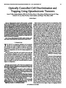
which can be numerically solved using the Newton– Raphson method to find γ. The rotation rate of the fluid shells in this model, as a function of distance from the centre of the particle, is shown in figure 1. It can be seen that although the heating effect is quite localised there can be a significant effect on the rotation rate and hence, the estimated viscosity. The experimental setup used for this experiment is described in [5], and in more detail in [21]. To characterise the viscometer the power dependence of the rotation rate and polarisation were determined (figure 2). A linear fit, through the origin, of the rotation rate as a function of power is shown (figure 2(a)). Contrary to expectation, the dependence is not perfectly linear which suggests that another parameter varies with the laser power. There is
40 35 30 25 2
3
4
5
6
Distance (µm)
60
heating no heating
40 20 0
We do not have an analytical expression for η(r), however in this form the integral can be easily calculated numerically. The torque, τ , in this equation is equal to the optically applied torque, given by equation 1 and is measured experimentally. The surface temperature of the particle is unknown and is required to determine η(r). The surface temperature, according to equation 2, depends on the parameter γ. However, from the empirical relation of viscosity as a function of temperature, which is derived from tabulated experimental data, and the relationship between temperature and distance, r, from equation 2, it is possible to rewrite equation 4 as:
45
80
2
(3)
where η is the viscosity of the surrounding liquid and Ω is the angular frequency of rotation of the sphere. This is the case even when the viscosity is non-uniform as long as its distribution within the fluid is spherically symmetric. The rotation rate of the fluid is equal to the rotation rate of the particle, at the particle’s surface, which we experimentally measure and is given by: Z r=a 1 τ d(1/r3 ) (4) Ω= 8π r=∞ η(r)
F (γ) = 0
140
3
4
5
6
Distance (µm)
FIG. 1: Rotation rate of the fluid in the equatorial plane as a function of the distance from the centre of the particle. The rotation rates correspond to a particular optical torque from an experiment with a vaterite particle, 3.2 µm in diameter. The solid line represents the case where the fluid has a temperature variation as shown in the inset. The temperature is constant throughout the fluid for the dashed line.
Rotation Rate (Hz)
dΩ d(r3 )
160
Change in Pol.
τ = 8πη(r)r6
180
Rotation Rate (Hz)
there will be a non-uniform distribution of fluid viscosity around the sphere. For certain liquids, experimental data exists which can be used to determine viscosity from temperature [19]. Theoretical models for viscosity as a function of temperature tend to be inaccurate over significant temperature ranges, so we use interpolated data to determine viscosity as a function of temperature. For steady state creeping flow, in an infinite viscous medium, driven by a rotating sphere, the fluid flow at any radius can be characterised by an angular velocity. As a torque must be applied to the rotating sphere to maintain the flow against viscous drag, there is a uniform outward flux of angular momentum equal to [20]:
200
(a)
150 100 50 0
(b) 0.36
0.35
0
50
100
150
200
250
Power (mW)
FIG. 2: The variation of rotation rate (a) and change in polarisation (b) with trapping laser power. The data is for a vaterite particle with a diameter 3.2 µm in methanol. The errors in these plots are small enough that the trends are significant. The absolute value of the power is not known precisely but the relative values of the powers in these plots are, and are limited only by the detector’s precision. The rotation rate is precise, provided enough revolutions of the particle are recorded, which means the deviation from linearity is significant. The error in the polarisation measurement is 0.005, yet the scatter is less than this which means the linear decrease with power is a real effect.
3 40
data quadratic fit linear comp. square comp.
150
Surface Temperature (oC)
Rotation Rate (Hz)
200
100
50
0
0
10
20
30
Optical Torque (pN µm)
40
50
FIG. 3: The variation of rotation rate with the optically applied torque. The components of the quadratic fit are shown. The linear component is the expected rotation rate without heating or non-Newtonian effects. The square component represents the non-linear effects on viscosity, which in this case, are due to heating that increases with laser power.
also unexpected behaviour of the change in polarisation as a function of power (figure 2(b)), which varies by several percent over the range of powers measured. In this case the dependence seems to be linear and a linear fit of the data is shown. It is possible that this trend could be caused by convection caused by heating of the fluid surrounding the sphere, or could be due to an increase in trap strength due to increasing the trapping laser power. However, the effect is minimal and would be difficult to confirm experimentally. Therefore we have not investigated the trend in this paper. Typically a viscometer measures viscosity by applying a known or controlled stress to the medium of interest, and then measures the resulting strain, which manifests as a shear rate in a liquid. In our microviscometer the applied stress is represented by the optically applied torque to the particle and the shear rate is related to the rotation rate. Therefore the rotation rate as a function of optical torque is the relationship of interest, and is depicted in figure 3. The form of the fit is: Ω(τ ) = ατ + βτ 2
(6)
where α and β are constants and τ is the optically applied torque. The nonlinear response could either be due to non-Newtonian behaviour of the fluid or a temperature effect. In this case, as the fluid (methanol) is Newtonian, there must be some heating occurring as the trapping laser power is increased. Absorption of the laser light by the liquid itself turns out to be of insufficient magnitude to explain the decrease in viscosity [22]. However, if the particle is itself slightly absorbing, then the heating
data linear fit 35
30
25
20
0
10
20
30
40
Optical Torque (pN µm)
50
60
FIG. 4: Surface temperature of the vaterite particle in methanol due to heating from absorption of the trapping laser. This is the maximum temperature in the surrounding liquid, the temperature falls off as r −1 , which is depicted in figure 1.
could be of sufficient magnitude to explain the observed behaviour. If this is the case, then the temperature of the fluid surrounding the particle is described by equation 2. Solving equation 5 for γ, gave a value for the rotation rate that matched the experimentally observed rotation rate of the particle. The surface temperature of the vaterite particle as a function of optical torque was found and is plotted in figure 4. A linear fit of the surface temperature data yields a temperature increase of 66 ◦ C/W of laser power. Commonly used laser powers, in our experiments and other optical tweezers experiments, are of the order of 100 mW, which corresponds to only a 7 ◦ C temperature increase. The observed temperature increase corresponds to 0.08% of the laser power being absorbed. Now that the power dependence of the measurements is characterised and understood, accurate measurement of viscosity of viscosity at room temperature is easily derived by making measurements at several power levels, which is easily done, and extrapolating to zero power. All the measurements discussed in this paper were made in this way. A good test of reproducibility is the microviscometer’s performance over a range of particle sizes. The result of this test is plotted in figure 5. For probe particles 2–5 µm in diameter, the viscosity measurements are consistent with the expected independence of viscosity on particle size. We also investigated the performance of our microviscometer over a range of viscosities. A series of solutions with different concentrations of glycerol were chosen because the relationship between viscosity and glycerol concentration has been well characterised [23]. In addition the glycerol polymers are short, which means the fluid ex-
4 represent the limits of our technique. Measurements of both lower and higher viscosities are possible, with the upper limit being determined by any user imposed time 0.7 restrictions on acquiring an accurate rotation signal. It is important to note that the volume of the sample used for these measurements was 10–15 µL, approximately one 0.6 drop of fluid. Dried vaterite particles were added to the sample using the tip of a brass wire while the sample was 0.5 on the microscope slide. This ‘in situ’ addition of vaterite is advantageous as it allows volumes as small as 1 µL to be handled. 0.4 Now that the microviscometer is fully characterised, it can be used for practical applications. An example of a medical sample, where only microlitre volumes are avail0.3 2 2.5 3 3.5 4 4.5 5 5.5 able is eye fluid. The viscosity of eye fluid has previously Particle Diameter (µm) [th] been measured to be 3–4 cP [13]. Without stimulating a tear response, only about 1–5 µL of eye fluid can be collected [13]. In a proof of principle experiment, we FIG. 5: The viscosity of methanol measured using vaterite measured the viscosity of a similar volume of stimulated with different diameters. This does not represent the the limit tears using our microviscometer. We found the viscosof the size range of vaterite particles, as particles as small ity to be 1.1 ± 0.1cP. In our experiment the collection as 1 µm and as large as 10 µm have been observed. However, viscosity measurements were not carried out with these procedure was safe but crude, so we expected the measpheres as the measurement of diameter become less accusured tear fluid viscosity to be close to water (0.97 cP at rate for small spheres and the larger particles tend to be less 21.5◦ C). In the future, more quantitative studies could spherical. be carried out by employing controlled and reproducible eye fluid extraction procedures developed by ophthalmologists [24]. 35 Probing very localised regions of fluid is an application accepted glycerol viscosity 30 experimental data that we have previously demonstrated by measuring the viscosity of a fluid inside a micelle [5]. In that experi25 ment the vaterite particles were added during the formation of micelles so that, on occasion, a vaterite particle 20 was engulfed by a micelle. A more interesting case is the viscosity inside a cell. In a proof of principle experiment, 15 we trapped and rotated a vaterite particle within a ‘bleb’ on a macrophage cell (figure 7). The bleb, an extended 10 region of the cell membrane, was formed by the cell in response to exposure to a focussed femto-second laser. The 5 vaterite was then inserted into the cell by simultaneously cutting a hole in the cell membrane with a femto-second 0 10 20 30 40 50 60 70 80 laser and pushing the vaterite through the hole in the Concentration of Glycerol (% by weight) membrane using an optical trapping laser beam. The viscosity was measured to be 3.3 ± 0.5 cP which suggests that the fluid was drawn into the cell through the memFIG. 6: Viscosity measurements for different concentrations of brane during bleb formation, as the surrounding fluid has glycerol. Each data point is the average of five measurements a viscosity close to water while intercellular viscosity has using five different particles. The error bars represent the been reported to be orders of magnitude higher [10, 11]. standard deviation and the error in measurement of particle diameter is primarily responsible for the data spread. The We have demonstrated a microviscometer that mearelative error for each data point is about 10–15%. sures viscosity by optically applying torque to a spherical probe particle and optically measuring both the torque and the particle’s rotation rate. The viscosities of glychibits Newtonian behaviour. The viscosities of different erol solutions varying by two orders of magnitude have concentrations of glycerol, as measured by our microvisbeen measured which demonstrates the lower limit of the cometer, are shown in figure 6 compared to accepted valdynamic range. Effects due to absorption of the trapping ues and show good agreement. The dynamic range tested laser, which causes local heating, have been accounted here was two orders of magnitude, however that does not for and quantified. Experiments within cells and with Viscosity (units of cP)
Viscosity (units of cP)
0.8
average viscosity experimental data
5
[7] [8] [9] [10] [11] [12] [13] [14]
FIG. 7: A phase contrast image of a vaterite inside a cell. The left arrow points to the cell membrane, or the ‘bleb’. The right arrow points to the vaterite within the cell membrane. The inset shows the normalised intensity, in arbitrary units, measured by the photo-detector used to determine the rotation rate of the vaterite particle.
[15] [16]
[17]
eye fluid have demonstrated the practical applications of this technique.
[18]
[19] [1] F. H. C. Crick and A. F. W. Hughes, Experimental Cell Research 1, 37 (1950). [2] A. R. Bausch, W. Moller, and E. Sackmann, Biophysical Journal 76, 573 (1999). [3] T. G. Mason, K. Ganesan, J. H. van Zanten, D. Wirtz, and S. C. Kuo, Physical Review Letters 79, 3282 (1997). [4] L. Starrs and P. Bartlett, Faraday Discussions 123, 323 (2002). [5] A. I. Bishop, T. A. Nieminen, N. R. Heckenberg, and H. Rubinsztein-Dunlop, Physical Review Letters 92, 198104 (2004). [6] J. C. Crocker, M. T. Valentine, E. R. Weeks, T. Gisler,
[20] [21]
[22] [23] [24]
P. D. Kaplan, A. G. Yodh, and D. A. Weitz, Physical Review Letters 85, 888 (2000). Z. Cheng and T. G. Mason, Physical Review Letters 90, 018304 (2003). M. Schmiedeberg and H. Stark, Europhysics Letters 69, 629 (2006). E. Andablo-Reyes, P. D´ıaz-Leyva, and J. L. Arauz-Lara, Physical Review Letters 95, 106001 (2005). P. A. Valberg and D. F. Albertini, The Journal of Cell Biology 101, 130 (1985). B. R. Daniels, B. C. Masi, and D. Wirtz, Biophysical Journal 90, 4712 (2006). V. Breedvald and D. J. Pine, Journal of Material Science 38, 4461 (2003). J. M. Tiffany, International Ophthalmology 15, 371 (1991). S. Parkin, G. Kn¨ oner, W. Singer, T. A. Nieminen, N. R. Heckenberg, and H. Rubinsztein-Dunlop, in Laser Manipulation of Cells and Tissues, edited by M. W. Berns and K. O. Greulich (Academic Press, 2007), vol. 82 of Methods in Cell Biology, chap. 19, pp. 525–561. T. A. Nieminen, N. R. Heckenberg, and H. RubinszteinDunlop, Journal of Modern Optics 48, 405 (2001). G. Kn¨ oner, S. Parkin, N. R. Heckenberg, and H. Rubinsztein-Dunlop, Physical Review E 72, 031507 (2005). J. Leach, H. Mushfique, R. di Leonardo, M. Padgett, and J. Cooper, Lab on a Chip 6, 735739 (2006). R. D. Leonardo, J. Leach, H. Mushfique, J. M. Cooper, G. Ruocco, and M. J. Padgett, Physical Review Letters 96, 134502 (2006). H. A. Barnes, J. F. Hutton, and K. Walters, An Introduction to Rheology (Elsevier, Amsterdam, 1989). L. D. Landau and E. M. Lifshitz, Fluid Mechanics (Butterworth-Heinemann, Oxford, 1987), 2nd ed. S. J. W. Parkin, G. Kn¨ oner, T. A. Nieminen, N. R. Heckenberg, and H. Rubinsztein-Dunlop, Proceedings of SPIE 5736, 59 (2005). E. J. Peterman, F. Gittes, and C. F. Schmidt, Biophysical Journal 84, 1308 (2003). J. B. Segur and H. E. Oberstak, Industrial and Engineering Chemistry 43, 2117 (1951). J. C. Pandit, B. Nagyova, A. J. Bron, and J. M. Tiffany, Experimental Eye Research 68, 247 (1999).