A superconducting accelerator-pumped free-electron laser (SCA/FEL) is used to perform photon echo experi- ments on a near-IR .... bandwidth of the fluctuation (
1652
J. Opt. Soc. Am. B/Vol. 8, No. 8/August 1991
Baiet al.
Picosecond photon echo experiments using a superconducting accelerator-pumped free-electron laser Y. S. Bai* S. R. Greenfield,
and M. D. Fayer
Department of Chemistry, Stanford University,Stanford, California 94305 T. I. Smith, J. C. Frisch,
t
R. L. Swent, and H. A. Schwettman
Hanson Experimental Physics Laboratory,Stanford University,Stanford, California 94305 Received June 5, 1990; revised manuscript received April 2, 1991
A superconducting accelerator-pumped free-electron laser (SCA/FEL) is used to perform photon echo experiments on a near-IR dye molecule in a polymeric glass. The SCA/FEL produces Fourier-transform-limited picosecond pulses at a repetition rate of 11.8 MHz. Its wavelength is continuously tunable. The experiments are conducted at 0.776 Am by doubling the output of the SCA/FEL tuned to 1.55 Aum. At this wavelength, the SCA/FEL is operated in a burst mode. The duration of the bursts (macropulses) is 2 ms with a repetition rate of 10 Hz. Each individual pulse (micropulse) has a length of 3.2 ps and is approximately 1 J in energy. In the experiment a number of single micropulses are selected from each macropulse. The doubling, stabilization, synchronization, single-pulse selection, and detection electronics are described. These are the first photon echo experiments and, to our knowledge, the first optical coherence experiments performed using a freeelectron laser as a source.
INTRODUCTION The Stanford Free-Electron Laser provides unique oppor-
tunities for investigating the properties of condensedmatter systems. The superconducting acceleratorpumped free-electron laser (SCA/FEL) has the potential to obtain information of fundamental importance on a wide variety of materials such as high-temperature superconductors, semiconductors (including amorphous materi-
als and multiquantum wells), inorganic and organic crystals and glasses, biological materials such as proteins and DNA, surfaces, polymeric solids, and liquids. It is the
distinctive operating characteristics of the SCA/FEL,
source. In this paper we describe the first photon echo experiments 2 conducted with a free-electron laser (FEL) and, to our knowledge, the first optical coherence (fourwave mixing) experiments of any type to employ a FEL. Experiments conducted with FEL's to date involve some form of absorption technique3 5 or simple third-harmonicgeneration measurements. 6 In comparison with these, the photon echo experiment is demanding. It requires precise control of the timing between pulses, the wave vector of the pulses, and the spot size of the pulses. It is necessary to select a limited number of single micropulses from each SCA/FEL macropulse. In addition, the experi-
ments were performed with the second harmonic of
which provides single, high-powered, picosecond pulses tunable across the IR spectrum, that make it possible to probe matter with methods that have not been readily available previously. The IR spectrum, which is not easily accessible with picosecond pulses, is extremely useful for understanding the properties of condensed-matter systems. Visible and UV light correspond to frequencies that are resonant with high-energy states of systems, i.e., electronic states of atoms and molecules. The IR, however, corresponds to the relatively low-energy states of molecular and atomic systems, e.g., the vibrational states of small and large molecules, polymers, and proteins, as well as the band gaps in novel semiconductors and multi-quantum-well structures and the pair energy gap in high-temperature superconductors. Thus the SCA/FEL, which is capable of producing continuously tunable picosecond pulses across the IR spectrum, can open new areas of materials research
the SCA/FEL operating wavelength. This means that the signal depended on the sixth power of the SCA/FEL intensity, which places a severe requirement on the SCA/FEL intensity stability. The photon echo experiments examined the molecule
for study.
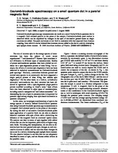
The SCA/FEL is located in a tunnel 9 m (30 ft) below the Hansen Experimental Physics Laboratory (HEPL) at Stanford University. A schematic is shown in Fig. 1. The FEL is pumped by a train of short (3 ps) pulses of electrons
Many modern picosecond optical experiments use nonlinear techniques. The requirements of ultrafast nonlin-
ear experiments place extreme demands on the laser 0740-3224/91/081652-05$05.00
1,1',3,3,3',3'-hexamethylindotricarbocyanine iodide (HITCI) in a polymeric glass, PMMA [poly(methyl methacrylate)]. HITCI is a large organic molecule that absorbs in the near IR [see inset Fig. 4(b)]. It has an
extended conjugated ir-electron system. Previously, smaller, more compact molecules have been studied in a variety of glasses,7' 0 including PMMA." The important questions in these experiments center on how the structure of a molecule influences its intermolecular interactions and dynamics in a glassy medium.
SCA/FEL CHARACTERISTICS
© 1991 Optical Society of America
Bai et al.
Vol. 8, No. 8/August 1991/J. Opt. Soc. Am. B
Experimental
1653
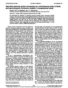
The optical pulse length is measured with a modified Spectra-Physics autocorrelator synchronized to the optical macropulse timing. A 1-mm-thick lithium iodate crystal is used to generate the autocorrelation signal. As shown in Fig. 2(b), the autocorrelation signal is well fit by a Gaussian with a FWHM of 3.2 ps. The signal is produced by a single macropulse and recorded by a 12-bit analogto-digital converter interface with an AT/PC computer. The spectra of both the individual pulses (optical micropulses) and the bursts (optical macropulses) are mea-
Room
sured with a monochromator and an array detector [Fig. 2(a)]. The spectra are near Gaussian and, when fit with Gaussian functions, have FWHM of 4.5 cm-' and
5 cm-', respectively. Thus the duration-bandwidth product of an individual pulse is 0.46, as compared with the theoretical value for a transform-limited Gaussian pulse (0.44). The difference between the micropulse and macropulse spectra gives a measure of the laser frequency
Fig. 1. Schematic of the SCA/FEL.
(micropulses) produced by a superconducting rf linear accelerator. The repetition rate of the electron micro-
jitter. From these measurements we find that the micropulse is Fourier transform limited with a peak
pulses is 11.8 MHz (84.6-ns separation),
power -0.3 MW (1 ,uJ/3.2 ps).
phase locked to
the 1.3-GHz operating frequency of the linac. The energy of the electrons is continuously variable from 20 to 180 MeV. A complete train of micropulses
is referred to
as a macropulse. The maximum duration of a macropulse varies with the electron energy, ranging from arbitrarily long at energies below approximately 30 MeV to approximately 1 ms (at a 10-Hz repetition rate) at the highest energies. At present, the average electron current during a macropulse is 200 ,.A, but system upgrades are expected to increase the average current to approximately
1 mA in
the near future. Because the accelerating rf cavities in the linac are superconducting, time constants associated with undesirable changes in the parameters of the electron beam are relatively slow (of the order of 0.1 ms).
._I
C,
3 I E
As a consequence,
straightforward feedback techniques can be employed to stabilize the electron beam and the FEL that it pumps. Such stabilization is far more difficult in accelerators utilizing normal conducting cavities, which have much faster time constants (of the order of 1 ,us). The exceptional stability of the optical beam produced by the SCA/FEL is a direct consequence of the feedback stabilization used. The SCA/FEL is run in a synchronously pumped modelocked fashion. The length of the laser cavity is chosen to be 12.7 m so that the round-trip time (84.6 ns) of the optical pulses matches the repetition rate of the electron micropulses. The cavity is symmetric and uses dielectric mirrors with 8-m curvatures. The end mirror is a high reflector, while the output coupling mirror has a transmission of approximately
2
0 Wavelength Offset (%)
,, 2 =3
0 0
1
1%.
For this experiment the SCA/FEL was operated at a wavelength of 1.55 gm, requiring an electron beam energy of 66 MeV. A macropulse duration of 2 ms was used, at a repetition rate of 10 Hz. Under these conditions the SCA/FEL was capable of delivering an average power (during the macropulse) of 12 W to the experiment. This corresponds to an optical micropulse energy of 1 ,uJ (12 W/11.8 MHz).
The optical beam is delivered from the tunnel to the experimental rooms at the ground level by an 80-m-long achromatic optical transport system (see Fig. 1). The efficiency of the transport system is approximately 60%.
0
2
0
40
0 AutocorrelationTime (ps)
Fig. 2. (a) Comparison between the spectrum of a single optical micropulse and that of a 3-ms optical macropulse consisting of 35000 individual micropulses. The FWHM of the micropulse spectrum is 0.069%of the center wavelength, while that of the macropulse spectrum is 0.077. (b) Autocorrelation signal of the SCA/FEL pulses. A Gaussian pulse of width 3.2 ps (FWHM) fits the data.
1654
Baiet al.
J. Opt. Soc. Am. B/Vol. 8, No. 8/August 1991
Beam Tube from
A pick-off beam is focused and passed through a pinhole and then detected by a quad detector (United Detector PIN-SPOT9D). This assembly permits us to monitor the beam alignment constantly and rapidly realign the system when necessary. A second AOM (Crystal Technology 3200) is used to select single pulses from the macropulses. Because of the slow micropulse repetition rate (11.8MHz), this is readily achieved with a rise time of 20 ns. The number of pulses
FEL
selected from a macropulse is continuously variable through an independent clock synchronized with the micropulse repetition rate by a flip-flop. In this experiment the number was limited by sample heating. Eight pulses in 2 ms, which corresponds to an experimental repetition rate of 4 kHz, was the maximum number that did not per-
turb the experimentalresults. The second AOM (pulse selector) also provides additional control of the intensity stability of the beam. The first AOM can only stabilize when the intensity is above the set point. The resulting FEL beam is stable except for occasional
I
Computer
Gated In r ,: Integrators,
MpM E AM
I-P PMT1
Fig. 3. Schematic of experimental setup: AOM's, acousto-optic modulators; DBS,dichroic beam splitter; QD,quad detector; BS's, beam splitters; PD's, photodiodes; PMT, photomultiplier tube; AMP's, transimpedance amplifiers.
PHOTONECHO EXPERIMENTAL SETUP Figure 3 shows a schematic of the photon echo experimental setup. The FEL beam is brought onto the experimental table by the transport system. The beam is collimated to a diameter (intensity) of -2 mm by a telescope. A 10 x 10 x 20 mm3 lithium iodate (LiIO3) crystal is used to double the laser beam to the experimental wavelength of 0.776 m, on the red side of the broad absorption band of the S 0-S, transition of the dye/glass system. The crystal is cut for fundamental wavelengths of 1.4-1.8 ,um (220). To reduce the walk-off effect, a pair of cylindrical lenses (f = 10 cm) are used to focus and recollimate the beam. With a single-pulse energy of 0.5 J at 1.55 Am, the second harmonic at 0.776,um is 100-120 nJ; i.e., the doubling efficiency is 20-25%. The intensity fluctuation of the fundamental beam is approximately 10%. After the frequency doubling, the fluctuation is increased to 20%. An acousto-optical modulator (AOM)(Intraction 40) driven by a feedback circuit is used to stabilize the laser intensity to within 1%. The AOM is inserted into the optical path after the doubling crystal. The transmitted beam is monitored by a silicon p-i-n photodiode. The signal is amplified by a current amplifier (LF 356, transimpedance gain = 10 k) and then sent into a feedback circuit. The circuit is composed of a single operational amplifier (LM 318). The response time of the whole system is 10 /is. Because of the small bandwidth of the fluctuation (1 MHz) often makes stabilization a formidable task.
dropouts.
A window circuit
(LM 319) is
used to control the second AOM so that it will not deflect the single pulse if the intensity falls below a preset level. Thus, only pulses within a narrow intensity distribution reach the sample. After the single-pulse selection, the beam is split to pass through two different optical paths. The length of one of the paths is variable by a computer-controlled stepper motor delay line. The two beams are then focused gently (f = 30 cm) and crossed at a small angle (1°) in the sample held in a liquid-He Dewar. A He-Ne laser beam made collinear with the single-pulse-selected beam after the second AOM is used for the alignment. Since the excitation beams are crossed at an angle, the photon echo pulses propagate in a unique direction and are thus spatially separated from the excitation beams. The echo is detected by a photomultiplier tube. The signal is amplified by a current amplifier and fed to a boxcar gated integrator (Stanford Research Systems SR250). The intensity of excitation pulses is monitored by a photodiode and measured by an identical current amplifierboxcar assembly. It serves as the reference signal. The time constants of the current amplifiers (2 s) are set to be the same, as are the gate widths of the boxcars. The outputs (last sample) of the boxcars are interfaced with an AT/PC computer through a 12-bit analog-todigital converter by a direct memory access channel. As mentioned above, there are eight single pulses selected from each macropulse. The amplitude of the reference signal of each single pulse is monitored by the computer in real time. If it does not fall within a preset window, the echo signal is not averaged in with previous shots. A ±5% window is used. Typically 70% of the shots fall within the window. During some periods of operation, 99% of the shots fall within this window. At each point on the delay line, a large number of shots are averaged. A typical decay curve takes about 3 min to obtain. Each excitation pulse is approximately 15 nJ. The laser spot size on the sample is -0.1 mm. The sample is the near-IR dye HITMI in PMMA. HITCI was dissolved with PMMA in methylene chloride. Clear films of thickness -1 mm and optical density -0.5 were obtained by holding the samples at room temperature under vacuum
Baiet al.
Vol. 8, No. 8/August 1991/J. Opt. Soc. Am. B
RESULTS AND DISCUSSION
(a)
Figure 4(a) shows an echo decay curve at 1.5 K. The signal-to-noise ratio is equivalent to or better than that taken on molecules that absorb in the visible using a conventional laser system."'1-3 Figure 4(b) displays a semilog plot of the same data. The echo decay is 284 ps and is a single exponential following a fast transient at t = 0. The echo decay time for an inhomogeneously broadened system is T2/4, where T2 is conventionally referred to as the homogeneous dephasing time."9 The FWHM of the linear absorption spectrum of HITCI at low temperature is =480 cm-'. This linewidth is similar to that of many other organic dyes in organic glasses at low temperatures. The large width arises from inhomogeneous broadening. At 1.5 K the homogeneous linewidth corresponding to the echo decay [284 ps, see Fig. 4(a)] is 280 MHz. Thus the inhomogeneous broadening is -105 greater than the homogeneous broadening. The fast transient [the sharp spike seen at the beginning of the scan in Fig. 4(b)] arises from the broad phonon sideband,'4 while the exponential decay reflects the optical dephasing of the zero phonon line of interest. It is should be noted that the phonon sideband dephasing process is quite insensitive to the temperature. For most materials, the dephasing time is shorter than 0.1 ps even at liquid-He temperature. Figure 5 shows the experimentally determined tempera-
/.
-Q En -
(b)
a
1655
3
2
._ C
0
0
200
400
600
Pulse Delay (ps) Fig. 4. Photon echo data. (a) Photon echo decay of HITCI at 1.5 K. The solid line through the data is a single exponential fit. (b) Semilog plot of same decay and fit. The spike at t = 0 is due
to the broad phonon sideband. The structure of HITCI is shown in the inset.
ture dependence on a log-log plot.
At each temperature
the excited-state lifetime ( = 1.9 ns) contribution to T2 has been subtracted from T2to yield T2*,the pure dephasing time, according to the relation 1/T2* = 1/T2 -
12r.
(1)
Detailed analysis of the temperature-dependence data is presented
elsewhere.'
5
Here we give only a brief descrip-
tion. The solid curve is a fit to the formula'6 to remove the solvent. The sample preparation procedure is identical to that described elsewhere," except that the samples in Ref. 11 were heated under vacuum to remove the solvent more quickly.
The photon echo decays were measured at 12 temperatures from 1.5 to 10 K. At the lowest temperatures (