ISTANBUL UNIVERSITY – JOURNAL OF ELECTRICAL & ELECTRONICS ENGINEERING
YEAR VOLUME NUMBER
: 2004 :4 :2
(1243-1248)
A CURRENT CONTROLLED CONVEYOR BASED PROPORTIONAL-INTEGRAL-DERIVATIVE (PID) CONTROLLER Cevat ERDAL1 1,2
Hakan KUNTMAN2
Selma KAFALI3
İstanbul Technical University, Electrical-Electronics Engineering Faculty 80626 Maslak, İSTANBUL / TURKEY 1
E-mail:
[email protected]
2
E-mail:
[email protected]
ABSTRACT A new PID controller realized with positive type, second generation current controlled conveyers (CCCII++) and passive components is presented. The outputs of SPICE simulations of the proposed circuit are verified with the theoretical expectations. Keywords: Current controlled conveyor, PID controller, and signal-flow graphs
1. INTRODUCTION Current controlled conveyors (CCCII) have recently considerable attention due to their wider and adjustable frequency band, lower power consumption, better linearity and stability properties and also providing electronically controllable characteristics to electronic circuits [1-6]. On the other hand, no other work has been carried out for the generation analog controllers in process control industry using CCCIIs at present except the ones by Erdal and Kuntman [1], although there are a vast number of electronic circuits realized with current controlled conveyors. The purpose of this study is to present a synthesis procedure for the realization of analog PID controller by the use of CCCIIs. This Received Date : 25.05.2003 Accepted Date: 15.06.2004
procedure is based on signal-flow graphs, which are very useful to design active electronic circuits. The circuit obtained satisfies the general transfer function of a PID controller and contained minimum number of CCCIIs. The SPICE simulations of the proposed circuit are fulfilled to verify the theoretical predictions.
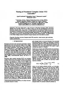
2. CURRENT CONTROLLED CONVEYOR The circuit diagram of a current controlled conveyor (CCCII) is shown in Figure 1 [1-7].
1244
A Current Controlled Conveyor Based Proportional-Integral-Derivative (PID) Controller
where Yy and Yz are the parasitic admittances between each port Y and Z and the ground, respectively. α(s) and β(s) are the current and voltage transfer gains of the conveyor, respectively.
3. SYNTHESIS PROCEDURE Consider the current conveyor circuits shown in Fig. 2. Using the defining equation of the active element the signal-flow graph of these circuits can easily be drawn [8].
Figure 1. a) Electrical symbol of the current controlled conveyor (CCCII) b) Equivalent circuit of CCCII The ideal current controlled conveyor can be described by the following equations: (1) I y = 0 , Vx = Vy + R x I x , I z = ± kI x
Where Vy, Vx, Iy, and Ix, are the voltages and currents of the positive and negative inputs, respectively. Vz and Iz are the output voltage and current, respectively. The positive k denotes a positive current controlled conveyor (CCCII+) and the negative sign denotes a negative current controlled conveyor (CCCII-), and k=1-ε, |ε|