PID plus fuzzy controller structures as a design base for industrial applications Leonid Reznik School of Communications and Informatics Victoria University of Technology P.O. Box 14428 MCMC Melbourne VIC 8001 Australia Email:
[email protected]
Omar Ghanayem Industrial Research Institute Swinburne P.O. Box 218 Hawthorn VIC 3122 Australia Email:
[email protected]
Anna Bourmistrov Department of Aerospace Engineering Royal Melbourne Institute of Technology GPO Box 2476V Melbourne VIC3001 Australia
Abstract This paper investigates the practical ways of designing effective combinations of classical PID controllers and emerging intelligent technologies for real-life industrial projects. It analyses the evolution of fuzzy controller (FC) design methodology. Based on the analysis, structures and methods that combine both approaches are proposed and considered. The paper is not intended to develop a mathematical theory, but to give some practical recommendations on replacing control by a human operator control with fuzzy control, and on on-line parameter tuning of FC parameters. These two main points are illustrated with two application projects, which are studied in greater detail. The first one includes the design of a FC supervising a PID control system in an automatic aircraft guidance system. The second project describes the tuning of the scaling factors of a fuzzy PID-type controller with other fuzzy systems, used in the excitation control of a synchronous power generator connected to an infinite bus through a transmission line. Keywords: Fuzzy control; PID controllers; Control-system design 1. Fuzzy control vs. PID control: fight or collaboration? Despite a lot of research and the huge number of different solutions proposed, most industrial control systems are still based on conventional PID regulators. Different sources estimate the share taken by PID controllers at between 90 and 99%. Some of the reasons for this situation may be given as follows. a) PID controllers are robust and simple to design. b) There exists a clear relationship between PID and system response parameters. As a PID controller has only three parameters, plant operators have a deep knowledge about the influence of these parameters and the specified response characteristics on each other. c) Many PID tuning techniques have been elaborated during recent decades, which facilitates the operator’s task. d) Because of its flexibility, PID control could benefit from the advances in technology. Most of the classical industrial controllers have been provided with special procedures to automate the adjustment of their parameters (tuning and self-tuning). However, PID controllers cannot provide a general solution to all control problems. The processes involved are in general complex and time-variant, with delays and non-linearity, and often with poorly defined dynamics. When the process becomes too complex to be described by analytical models, it is unlikely to be efficiently controlled by conventional approaches. In this case a classic control methodology can in many cases simplify the plant model, but not provide
good performance. Therefore, an operator is still needed to have control over the plant. Human control is vulnerable, and very dependent on an operator' s experience and qualifications, and as a result many PID controllers are poorly tuned in practice (Wang et al., 1999). A quite obvious way to automate the operator’s task is to employ an artificial intelligence technique. Fuzzy control, occupying the boundary line between artificial intelligence and control engineering, can be considered as an obvious solution, which is confirmed by engineering practice. According to the survey of the Japanese control technology industry conducted by the Japanese Society of Instrument and Control Engineering (Takatsu and Itoh, 1999), fuzzy and neural control constitute one of the fastest-growing areas of control technology development, and have even better prospects for the future. The attraction of a fuzzy controller (FC) from the process-control point of view can be explained by the fact that a FC provides good support for translating both the heuristic knowledge about the process of a skilled operator, and control procedures (expressed in imprecise linguistic sentences), into numerical algorithms. In a typical PID controller design for industry, the controller parameters are initially determined and then tuned manually to achieve the desired plant response. In the approach described in (Copeland and Rattan, 1994), manual tuning can be replaced with a FC supervising a tuning process. The resulting improvements in the system response are accomplished by making on-line adjustments to the parameters of the FC. As PID controller design theory and practical procedures are well developed, attention needs to be paid to FC design, and its applications in combinations with a PID. Control engineers report a shortage of practical design tools and recommendations as the main obstacle to wider FC implementation in industry (Takatsu and Itoh, 1999). This paper does not aim at developing a mathematical theory, but at providing some practical recommendations for replacing control by a human operator with a FC, and for choosing the structure and parameters of this FC. These recommendations are summarised briefly in Table 1, which is reproduced from (Reznik 1997a), where more information is provided. In particular, this paper focuses on two problems: replacing an operator’s control of PID regulators with a PID-FC combination (Sections 3-4) and the development of a universal structure for autotuning FC scaling factors (Section 5). The proposed methods are illustrated by the solution of two practical problems. Section 2 reviews and classifies FC design approaches, as applied to date. Based on this analysis, a PID-FC combination design is derived in Section 3. Here, different PID-FC structures are investigated for the particular case of the PID-FC aircraft guidance control, described in Section 4. Section 5 proposes a method of online FC parameter tuning, in which a methodology similar to PID coefficient adjustment is employed. The results of its application in the excitation control of a synchronous power generator are given. 2. Fuzzy controller design approaches. FC design is still more a matter of art than technology, and the area where a designer’s expertise plays the main role. Investigating the roots of this situation, the following reasons can be put forward. 1. Fuzzy control theory, and especially FC design theory, are far from complete or even being fully developed. C.-C. Lee (1990) stated in his survey that “there is no systematic procedure for the design of a fuzzy controller”. Brehm and Rattan (1993) asserted that “the design methodologies are in their infancy and still somewhat intuitive”. The lack of mathematical rigour in FC analysis and design was confirmed recently by Patyra and Mlynek, (1996) and by Ma et al. (1998) as well as in a paper devoted specifically to a PID-type FC design (Mudi and Pal, 1999). However, this area is being very intensively developed. An excellent review of the current state of FC design, as well as its relationship with classical control, is given in (Verbruggen and Bruijn, 1997). 2
2. Fuzzy controller design is situated along a “border line” in the research field, where quite different approaches are applied; artificial intelligence (expert systems) and control engineering and optimisation theory, to name the main ones. Combining these different methods could significantly enrich the fuzzy control methodology, bringing about new and amazing results. However, behind the various approaches, one can see different communities, traditionally applying various methodologies and criteria in their evaluations, and having some lack of understanding (and sometimes even some misunderstanding) of each other’s methods. Basically, all the approaches to FC design can be classified as follows: 1) expert systems approach, 2) control engineering approach, 3) intermediate approaches, 4) combined approaches and synthetic approaches. The first approach originates from the methodology of expert systems. It is justified by consideration of an FC system as an expert system, applied to problem-solving in control. In this approach, fuzzy sets are used to represent the knowledge or behaviour of a control practitioner (an application expert or an operator) who may be acting only on subjective or intuitive knowledge. All the theoretical and practical methods of knowledge acquisition developed in artificial intelligence and cognitive sciences are to be practised here. One should note that by using linguistic variables, fuzzy rules provide a natural framework for human thinking and knowledge formulation. Many experts find that fuzzy control rules present a convenient way to express their domain knowledge, so cooperation with the experts would be easier for a knowledge engineer. This approach was very popular in pioneering FC design. In a purely expert approach, the choice of the structure, inputs, outputs and other parameters of a FC system is the sole and solemn responsibility of the expert(s). Moreover, the supporters of this approach warn against further parameter modifications, pointing out that such adjustments can jeopardise an expert’s instructions. Changing the scaling factors and/or membership functions, for example, may result in losing the original linguistic sense of the rule base. The experts may not recognise their rules after tuning, and will then not be able to formulate new rules. Generally speaking, in this approach an expert system is designed. This expert system is specified for control applications and, after the design is completed, operates as a FC. In this approach, any structure and set of the parameters of the FC can be chosen. Supporters of the control engineering approach consider the approach described above as too subjective and prone to errors, and try to make a choice on the basis of some objective criteria. This approach proposes to design a FC by investigating how the stability and performance indicators depend upon different FC parameters. Thus, this approach clearly incorporates an analysis of an FC as one of the important stages of design. To evaluate a quality of such an FC, the criteria commonly used in control engineering practice are applied. Intermediate approaches propose setting some of the parameters (e.g., membership functions) by the experts, and fixing the others (e.g., rules) with the methods inherited from control-system design. Combined approaches include an initial choice of the FC structure and parameters, made by an expert, and further their adjustment performed using the control engineering methods. The development of these methods has led to the application of models, which computationally synthesise the properties of expert production systems, neural networks, and fuzzy logic. The example of a such methodology is ARTMAP (Carpenter and Grossberg, 1996) - a family of selforganising neural architectures that are capable of rapidly learning to recognise, test hypotheses, and predict the consequences of analog or binary input patterns occurring in nonstationary time series. Another area of the application of a combined approach has come from control engineering practice. In a typical PID controller design for industry, the controller parameters are determined 3
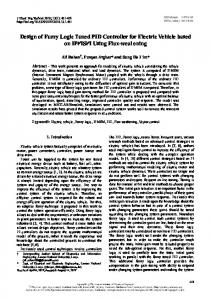
initially, and then later tuned manually to achieve the desired plant response. In this approach, manual tuning can be replaced with FC supervision of a tuning process. The resulting improvements in the system response are accomplished by making on-line adjustments to the parameters of the FC. It should be noted that an expert-systems approach was very popular at the beginning, though it is still being applied nowadays, of course in a modified way. An example of such an application is given in (Kim and Zeigler, 1996), where a multiresolutional search scheme based on genetic algorithms (GA) is employed in FC design. Considering the advantages of both (AI and control engineering) approaches, one can conclude that the AI approach allows one to capture the vagueness of a human knowledge in FC design, and to express the design framework using natural languages. It leads to that feature of FC which is becoming more and more important, especially in design applications: the design process for an FC becomes more understandable, looks less sophisticated and superficial to a human designer, and becomes more attractive (and therefore cheaper) than a conventional one. The control engineering approach allows traditional criteria to be applied in FC design, and design methodologies to satisfy conventional design specifications to be developed, including parameters such as an overshoot, an integral and/or a steady-state error. Enhancing FC engineering methods with an ability to learn, and the development of an adaptive FC design, would significantly improve the quality of an FC, making it much more robust and expanding its area of possible applications. 3. Combination of fuzzy and PID controllers as a basic structural choice In order to achieve both high performance under specified operating conditions and the desired possession of some other features (first of all, stability and robustness to changes in the operating environment, two basic structures are widely exploited in FC design: hierarchical structures including a supervisory controller, and adaptation procedures. A hierarchical rule-based controller usually consists of a simple upper-level controller, which is often called a "supervisory controller" (Wang, 1994) and the low-level controller(s). The switching between the levels can be realised by a fuzzy controller as well. The application of a hierarchical structure lets the solving of different problems be distributed among the levels, and allows various criteria to be applied in the construction of the different controllers. The top-level controller should provide an approach to the main goal of the system, while the low-level controllers should deliver the solutions to particular problems. An application example of this structure is a multi-layer fuzzy controller (MLFC), which was proposed and applied to high-performance tracking of induction motors (Huang and ElSharkawi, 1996). The MLFC has two layers. The first layer is an execution layer, which is made up of small subcontrollers. The second layer is the supervisory layer, which combines the execution layer subcontrollers to achieve the system objectives. The design and tuning of the controller are simplified because of the layered topology. The low-level controller(s) can quite often be implemented as conventional PID controllers (Fig. 1a). In this case a high-level FC can realise a rule set used for a low-level parameter adjustment, directly replacing an operator. Note that an FC can perform both on-line and off-line parameter changes. This means that it can work at the same time as a conventional PID controller, as well as before and after it. In some cases an FC can be applied only for the prevention of potentially dangerous situations in process control. The design of a fuzzy-logic supervisor for PID control of unknown systems was carried out in (Copeland and Rattan, 1994). The objective of the fuzzy supervisor is to gradually increase the derivative gain of the controller, as the system error approaches zero (Fig. 1d). When the error and the change in the error are in the zero membership regions, the proportional gain is increased to improve the settling time of the system, and an integral gain, if required, is added to eliminate 4
steady-state error. The switching between different PID controllers, operating during either a transient or a steady-state period, can be realised as a neuro-fuzzy combination. This structure allows learning (Chen and Chan, 1996). In this controller, the PD mode is used in the case of large errors to speed up the response, whereas the PI mode is applied for small error conditions to eliminate the steady-state offset. A sigmoid-like neuron is employed as a pre-assigned algorithm of the law of a structural change. Meanwhile, the controller parameters would be changed according to local conditions. Bounded neural networks or bounded fuzzy-logic systems are used for constructing the nonlinear relationship between the PID controller parameters and local operating control conditions. Flexible changes of controller modes and resilient controller parameters of the neural/fuzzy combination during the transient could thereby solve the typical conflict between a steady-state error and dynamic responsiveness. In some cases (Cavalcanti, 1996) a fuzzy switch is applied as a supervisory controller between a PID and a neural controller (Fig. 1e). An interesting approach in exploiting some similarities between fuzzy and PID controller design is based on consideration of FCs as gain-scheduling approximators (Palm and Rehfuess, 1995). With the help of weighting, fuzzy gain scheduling interpolates the fuzzy rules through different degrees of membership and a corresponding computation of the mean value, considering all the rules. On the other hand, this similarity between PID gain factors and FC scaling factors can be employed in FC design and tuning, this is considered in greater detail in Section 5. Another way of producing fuzzy-neural-PID combinations can be performed by placing fuzzy, neural and PID controllers at the same level. Here, both series and parallel structures are considered. In a serial connection (Fig. 1c) an FC develops an input signal for a PID. In most cases this FC replaces a human operator, and is designed as a simple expert system. This method has been employed for some time, starting with the work of Tzafestas and Papanikolopoulos, (1990) and Zhong et al. (1993). Theoretical investigation of the stability of such structures has been conducted (Malki et al. 1994) and (Misir et al. 1996). However, in this case the control engineering approach surpasses the expert opinion. In a parallel connection (Fig. 1b) an FC develops an extra control input which is applied to the plant in some combination with a PID control signal, or one of conventional PID inputs is replaced with an FC (Li, 1998). These structures are good at nonlinear plant control and for systems working under conditions including strong disturbances. In (Liang and Qu, 1993) an FC is applied to the PID control method, and a self-optimal regulating factor is added to the control rule; thus the controller not only has the quick dynamic response of the FC, but it also has the high steady-state accuracy of a PID. The structures described above have proven to be very effective in a number of applications, providing the required performance and stability of the whole system, and comparing favourably to a variety of conventional techniques attempted to date. Unfortunately, except for (Ordonez et. al., 1997) and (Reznik and Ghanayem, 1994), the authors know no references comparing fuzzy hierarchical and adaptive controllers. Two practical examples illustrating an application of these structures are given below. The first one includes the design of an FC replacing an operator in a PID supervisory control system. The second demonstrates the application of a complex FC structure, used to tune the input and output scaling factors of the main FC. 4. Fuzzy controller as a supervisory controller for PID aircraft guidance control A modern aircraft is well equipped with conventional control techniques, and in particular various PID controllers, which demonstrate good performance in solving different guidance problems. Guidance control is performed by PID controllers producing the control signals, which are applied to ailerons and elevators. The necessary reference inputs for a PID are usually supplied by the aircraft crew, based on various data, first of all the current position as provided through the global positioning system (GPS). 5
Some classes of piloted aircraft are to be replaced with autonomous vehicles, which are cheaper in operation and have other advantages. A hybrid guidance control system, incorporating conventional PID controllers and a fuzzy controller, is proposed for such an aircraft. A fuzzy controller takes the place of a pilot (an operator) in developing reference signals for a PID controller. The navigation of a self-piloted vehicle is organised by an onboard GPS receiver, tied to a PCbased flight director. Flight-planning software generates a list of consecutive points, necessary to track a mission on a pre-determined flight trajectory. Onboard autopilots keep the aircraft stable, while the flight director (guidance system) interprets the waypoint positions to determine the course, speed, climb rate and turns of the aircraft. An objective of the guidance system is to bring the aircraft to the next operational waypoint at a specified altitude, and to stabilise the vehicle to allow for the operation of the onboard photographic and/or measurement equipment. The aircraft is assumed to be guided to an apropriate initial position during a take-off stage, before the guidance system takes over control. The designed control structure is shown schematically in Fig. 2. The altitude of the aircraft is controlled by a low-level conventional PID feedback controller, through aerodynamic ailerons and an elevator with mechanical limits on their deflection angles. The speed of the aircraft is controlled by a throttle setting. The fuzzy guidance controller has to provide reference signals for a PID controller, which requests roll and pitch angles (φref and θref respectively) for level flight, and also to produce the throttle setting command Tth if a change of altitude is required. The operation of the FC developed for this work is illustrated in Fig. 3. The coordinates of the aircraft' s current position and of the next operational point are used to estimate an offset angle, δ, between the direction to the operational point and the current velocity vector, v , and the rate of change of the offset angle, δ , as well as an altitude difference between the current position of the aircraft and the operational altitude, h, and the rate of change of the altitude difference, h . These estimates become the input signals for the fuzzy controller, and are subject to fuzzification. The whole control structure consists of three fuzzy controllers, operating independently, with each of them having two inputs and one output signal. This input-output mapping provides a simple two-dimensional structure of the linguistic rule sets. The fuzzy controller output mainly depends on the definition of the membership functions and the rules. The domains of the control variables δ, δ and h are divided into seven linguistic classes with relative memberships, and the control variable h is divided into five. The rule definition is subjective, and is based on an expert’s knowledge and experience. For a system with two control variables and seven membership functions in each range, this may lead to a 7×7 decision table, for example. A total of three rule sets is used in this fuzzy controller design: for the roll angle control, for the pitch angle control, and for the throttle position control. These rule sets can be viewed as 7×7, 7×5 and 7×5 decision tables, respectively. Simplicity and a low implementation cost determine a choice of the membership functions of a singleton type for the output parameters (roll angle, pitch angle and throttle position). The linguistic variables of the fuzzy outputs evaluated by cycling through the rule sets are projected onto output sets of the memberships. The defuzzification process takes place after a generation of fuzzy control signals is completed by an inference mechanism. As more than one fuzzy output variable can be assigned a nonzero degree, a contribution of each variable into a physical output should be taken into account. The defuzzification method based on calculating the centre of gravity of all fuzzy outputs for each system physical output was employed. Fig. 4 demonstrates the results of a fuzzy-PID structure application to the control of a selfpiloted aircraft. In the example given the task was to direct an aircraft to the destination point. The final errors in positioning of the aircraft with respect to the target point and the altitude 6
errors were taken as measures of performance. The orientation error was defined as the offset angle between the direction to the arrival point and the direction of the current velocity vector. In the plot the positioning errors are elliptically spread, indicating a normal distribution of the coordinate errors. 5. On-line fuzzy PID-like controller parameters tuning In FC design an appropriate selection of input and output scaling factors is very important because of their significant effect on the controller stability and performance [Mudi and Pal, 1999]. Many reports on scaling factor adjustment are available that allows to choose useful features of different approaches. Here we concentrate only on those, which suppose tuning performed by another fuzzy system. In comparison to a neural network application this method allows to avoid delays associated with network training. Some approaches base the tuning algorithms on the model of the object or process under control (derived or assumed). [Palm 1995] adjusts the input scaling factors with the help of an input-output cross-correlation function. Modern techniques include both neural networks and genetic algorithms [Pham and Karaboga, 1999] as well as tuning of PD-type [Chao and Teng, 1997] and PI-type [Chung et. al., 1998] FCs. However, the most interesting approach in our opinion tries to extend the methods of PID coefficients tuning to FC scaling factors adjustment. [Zheng 1992] recommended selecting input and output scaling factors from the knowledge of conventional PI-controller parameters if available. [Hayashi, 1991] calculated scaling factors using a concept of tuning rules for a classical PI controller as well. Some works [Galichet and Foulloy, 1995], [Moon 1995] try to provide a theoretical analysis of the equivalence between PID and FC controllers. The adaptive FC structure proposed in this paper includes adaptation mechanisms that are able to alter an operation of the FC by varying its internal parameters. The structure has been developed for tuning FC scaling factors. Unlike many other projects, here an automatic simultaneous tuning of both the input and output ranges of the FC is applied. Adaptation mechanism is based on the analysis of the status of the controller in respect to some performance criteria. The criteria can be selected by a designer and changed. The rule base and membership functions are updated and modified in an implicit manner. The structure under consideration is able to handle both transient and steady state operational conditions. It consists of the fuzzy controller and universal tuners used to change its scaling factors. Fig. 5 introduces the idea of this structure operation with the main PID-type FC and two other blocks performing new scaling factors (ranges) definition and new control signal calculation. The main problem in tuning scaling factors was to develop the methodology for simultaneous on-line tuning all of them, input as well as output. In this problem solving an experience with the PID controller coefficients adjustment played a role, which was hard to underestimate. The idea of similarity between FC scaling factors and PID coefficients (see fig. 6) and a possibility of extending the tuning methodology to FC was employed here. Based on this idea, the recommendations on how to tune the scaling factors have been developed. For various scaling factors of a PI-type FC table 2 gives a direction of change which is to be taken to satisfy different criteria (see [Reznik, 1997] for more detail). Fig. 7 provides more explanation about the system structure and operation. Main FC is a classical PID-type FC. The expert knowledge is implemented in this controller rules and classes. An adaptation process is performed by tuning and updating the parameters of this controller. A universal tuner part consists of the following blocks: 1) Operational Status block 2) Operational Sector block 3) Input and Output Range Tuning Blocks (Shay_Tune) 7
4) Phase and Amplitude Enhancement block (Shay P/A) Operational Status block produces a semaphore signal indicating the suitability of the current input and output ranges of the main FC. The signal value depends on the comparison results between the current control signal and its upper and lower limits, which are given in the controller specification. The upper and lower limits of the main controller response have the great importance in the operation of this block. Operational Sector block implements a quite simple procedure of performance indicator calculating and making a decision about its current state belonging to one of 6 types which determine the following fuzzy processing. The input to this block is a performance monitor. Quite commonly an error signal can be applied as such a monitor. The objective of this block is to generate a vector, representing the current operational sector. The operational space is subdivided into 6 operational sectors. Any sector determines a distinctive way of further information processing and signal calculations. The definition of the operational sectors has proved to be a very useful tool for later fuzzy processing stages while updating the input and output ranges of the FC. The position of the current system state (which sector it belongs to) is determined by comparing two consecutive measures of the performance monitor. Input and Output Range Tuning Block serves for on-line updating of the main FC both input and output scaling factors during the running time. The updating is based on using parameters from the operational environment and the main FC. Phase and Amplitude Enhancement Block performs a stepwise enhancement of the output control signal (U). It implements the PD-type FC (see [Gnanayem and Reznik, 1997] for further details). The proposed system was applied for the excitation control of a laboratory setup of a synchronous generator connected to an infinite bus through a transmission line. Both the rotor angle and the terminal voltage were catered for in this design. The structure includes both a power system stabiliser (PSS) and a regulator (AVR) that senses and regulates the generator terminal voltage. The application of the real time adaptive PID-type FC for the stabilisation of the power excitation control is illustrated in Fig.8. The parameters of the generator and the transmission line are given in the table 3. The performance monitor used was derived in a Pre-Control stage. The system was implemented using a digital signal processing board, Texas Instruments floating point DSP (TMS320C40). Different tests were conducted with and without the fuzzy adaptive structure developed. The tests performed could be classified into following categories: sudden load changes, reference voltage changes and transmission line short circuits. A few examples are given below. Note that the dotted line represents the response with no fuzzy control while the solid line represents the response under the control of the proposed adaptive structure. Fig. 9 demonstrates the speed response when the machine was operating under a rated load and 0.95 power factor (lag), it was then subjected to 75% change of rated load, sudden inductive load increase sustained for 10 seconds, then removed. Fig. 10 illustrates the case of a load drop for 30% during the period of 5 sec when the power factor was 90%. Fig. 11 shows the rotor angle change with time when the transmission line was subject to short circuit for 100 msec and the power factor was 0.9 (lag). The tests were performed under a very wide range of the operational conditions. Operation points P1 and P2 represent the normal and up-normal operational conditions. The developed structure was still able to adapt to the new environment and secure the stability of both the rotor angle and the terminal voltage. The tests undergone have confirmed the potential of the proposed universal approach in design of complex engineering systems. The test results highlight the superiority of the proposed structure. The superiority of the proposed scheme can be explained by the following facts:
8
1) it gives a good chance for better tuning of the main FC parameters in the design stage, considering that the input/output ranges problem is solved by an extra FCs, 2) the structure of the additional FCs is system independent. 3) the on-line operation of the developed structure supports the overall control loop robustness under variations of operating conditions. 6. Conclusion. Fuzzy controllers can play an important role in design of new synergetic controllers, which may gradually replace PID controllers in different applications. Interesting enough, PID and fuzzy controllers combinations not only can produce a better quality control, but some similarity between them can be utilised in FC design as well. Both avenues are exploited in this paper. The design methods for these synergetic projects are discussed. Different structures are proposed and analysed in the paper. Two examples of practical engineering design illustrate two main points of the paper: the advantage of the fuzzy and PID controllers collaboration in both design and operation of control systems. Acknowledgement The authors would like to thank all the referees for detailed comments and recommendations, which have helped to improve the paper quality. References Brehm, T. and Rattan, K.S.,(1993) Hybrid fuzzy logic PID controller. Proceedings of the IEEE 1993 National Aerospace and Electronics Conference. NAECON 1993 p. 807-13 vol.2, IEEE, New York, NY, USA Carpenter G. A. and Grossberg S. (1996) Learning, Categorization, Rule Formulation, and Prediction by Fuzzy Neural Networks In: Fuzzy logic and Neural Network Handbook/ed. C.H. Chen, McGraw-Hill, 1996 Cavalcanti J.H.F. (1996) Intelligent control system using PID and neural controllers 38th Midwest Symposium on Circuits and Systems. Proceedings vol.1, IEEE, New York, NY, USA p. 425-428 Chao Ch.-T. and Ch.-Ch. Teng (1997) A PD-like Self-Tuning Fuzzy Controller without SteadyState Error, Fuzzy Sets and Systems, vol. 87, p.141-154 Chen, C.-L. and Chang, F.-Y. (1996) Design and analysis of neural/fuzzy variable structural PID control systems IEE Proceedings-Control Theory and Applications, 143, 2, p.200-208 Chung H.-Y., B.-Ch. Chen, and J.-J. Lin (1998) A PI-type Fuzzy Controller with Self-Tuning Scaling Factors, Fuzzy sets and Systems, vol.93, p.23-28 Copeland R. P. and Rattan K. S.(1994) A Fuzzy logic Supervisor for PID Control of Unknown Systems. Proceedings of IEEE Symposium on Intelligent Control, 16-18 August 1994, Columbus, OH, USA, pp 22 – 26 Galichet S. and L.Foulloy, (1995) Fuzzy Controllers: Synthesis and Equivalence , IEEE Transactions on Fuzzy Systems, vol. 3, p. 140-148 9
Ghanayem O. and Reznik L.(1997) Excitation Control of a Synchronous Generator Using an On-Linear Adaptive Fuzzy Logic Controller Structure Proceedings of the 6th IEEE International Conference on Fuzzy Systems, July 1-5, 1997, Barcelona, Spain, IEEE Neural Networks Council, vol. 3, pp.1493 - 1498 Hayashi S. (1991) Auto-Tuning Fuzzy PI Controller in Proceeding of the International Fuzzy Systems Association Congress, Brussels, belgium, p.41-44 Huang, T.C. and El-Sharkawi, M.A. (1996) High performance speed and position tracking of induction motors using multi-layer fuzzy control, IEEE Transactions on Energy Conversion, 11, 2,353-358 Kim J. and Zeigler B.P. (1996) Hierarchical Distributed Genetic Algorithms: A Fuzzy Logic Controller Design Application IEEE Expert, June 1996, pp.76 - 84 Lee, C.-C.,(1990) Fuzzy logic in control systems: Fuzzy logic controller . IEEE Transactions on Systems, Man, and Cybernetics, vol. 20, No.2, p. 404 - 435 Li W. (1998) Design of a Hybrid Fuzzy Logic Proportional Plus Conventional IntegralDerivative Controller IEEE Transactions on Fuzzy Systems, vol. 6, No. 4, p. 449-463 Liang X. and Qu B.(1993) Fuzzy-PID controller Proceedings TENCON ' 93. 1993 IEEE Region 10 Conference on ' Computer, Communication, Control and Power Engineering'vol.4 IEEE New York, NY, USA , p. 296-299 Ma X.-J., Z.-Q. Sun, and Y.-Y. He, (1998) Analysis and Design of Fuzzy Controller and Fuzzy Observer, IEEE Transactions on Fuzzy Systems, vol. 6, No. 1, p. 41-51 Malki H.A., H.D.Li, and G.Chen (1994) New Design and Stability Analysis of Fuzzy Proportional- Derivative System, IEEE Transactions on Fuzzy Systems, vol. 2, p.245-254 Misir D., H.A. Malki and G.Chen (1996) Design and Analysis of Fuzzy Proportional-IntegralDerivative Controller, Fuzzy Sets and Systems, vol. 79, p.297-314 Moon B.S., (1995) Equivalence between Fuzzy Logic controllers and PI Controllers for Single Input Systems, Fuzzy Sets and Systems, vol. 69, p.105-113 Mudi R.K. and N.R. Pal , (1999) A Robust Self-Tuning Scheme for PI- and PD-Type Fuzzy Controllers IEEE Transactions on Fuzzy Systems, vol. 7, No. 1, p. 2-16 Ordonez R. et. al.(1997) Adaptive fuzzy control: Experiments and Comparative Analyses, IEEE Trans. on Fuzzy Systems, 5, 2, 167-188 Palm R. and Rehfuess U. (1995) Fuzzy Controllers as Gain Scheduling Approximators, Fuzzy Sets and Systems, vol.85, p.233-246 Palm R. (1995) Scaling of Fuzzy Controller Using the Cross-Correlation, IEEE Transactions on Fuzzy Systems, vol. 3, No. 2, p. 116-123 10
Patyra M.J. and D.M.Mlynek/Eds., (1996) Fuzzy Logic: Implementation and Application WileyTeubner, Chichester Pham D.T. and D. Karaboga (1999) Self-Tuning Fuzzy Controller Design Using Genetic Optimisation and Neural Network Modelling, Artificial Intelligence in Engineering, vol. 13, p.119-130 Reznik L.(1997) Fuzzy Controllers Newnes-Butterworth-Heinemann, Oxford, Reznik L. and Gnanayem O. (1994) Hierarchical Versus Adaptive Fuzzy Logic Controllers: Design and Performance, 2nd Australian and New Zealand Conference on Intelligent Information Systems, Brisbane, November 29 - December 2, 1994, pp. 224 - 228 Reznik L. (1997) Evolution of Fuzzy Controller Design, Proceedings of the 6th IEEE International Conference on Fuzzy Systems, July 1-5, 1997, Barcelona, Spain, IEEE Neural Networks Council, vol. 1, pp.503 – 508 Takatsu H. and T.Itoh, (1999) Future Needs for Control Theory in Industry - Report of the Control Technology Survey in Japanese Industry, IEEE Transactions on Control Systems Technology, vol. 7, No.3, p.298 - 305 Tzafestas S. and N.Papanikolopoulos (1990) Incremental Fuzzy Expert PID Control, IEEE Transactions on Industrial Electronics, vol.37, p.365-371 Verbruggen H.B. and P.M.Bruijn, (1997) Fuzzy Control and Conventional Control: What Is (and Can Be) the Real Contribution of Fuzzy Systems? Fuzzy Sets and Systems, vol. 90, p. 151160 Wang Li-Xin (1994) A Supervisory Controller For Fuzzy Control Systems That Guarantees Stability. IEEE Transactions on Automatic Control, vol.39, No. 9, pp. 1845 – 1847 Wang Q.-G., T.-H. Lee, H.-W.Fung, Q.Bi, and Y.Zhang, (1999) PID Tuning for Improved Perofrmance, IEEE Transactions on Control Systems Technology, vol. 7, No.4, p.457-465 Zheng L., (1992) A Practical Guide to Tune of Proportional and Integral (PI) Like Fuzzy Controllers in Proceedings of the 6th IEEE International Conference on Fuzzy Systems, March 1992, San Diego, Ca, IEEE Neural Networks Council, p. 633-641 Zhong H.S., T.Shaohua, and W.P.Zhuang (1993) Fuzzy Self-Tuning of PID Controllers, Fuzzy Sets and Systems, vol.56, p.36-46
11
Fuzzy
Fuzzy
control
control ler
ler
Control
Error PID
PID
Fuzzy
Control
control
Control
control
control
ler
ler
ler
a
PID control ler
b
c
PID control ler
PID
Fuzzy
control Control
ler
control
Fuzzy
ler
PID
Control
control ler
Neural
control
control
ler
ler
d
e
Figure 1. Fuzzy-Neural-PID control structures GPS Data
Reference Trajectory Data
T th
Fuzzy Conroller
φ
ref
,θ
PIDC ref
δa,δe
Aircraft Model
Figure 2. Structure of the combined control system Memberships for input parameters
Rule sets
Memberships for output parameters
δ Set of Rules for Roll Angle
. δ Input parameters h
ϕ Output parameters θ
Set of Rules for Pitch Angle
. h
T
Set of Rules for Throttle Pos. Fuzzification
Rule evaluation
th
Defuzzification
Figure 3. Operational block diagram of the fuzzy control system 1300
Way point= (1100, 1200)
Y, m 1250
1200
1150
1100
1050 700
2σ Probability Contour 3σ Probability Contour 800
900
Mean=(1081.2,1182.8)
1000 X,m
1100
1200
1300
1400
Figure 4. Arrival points distribution for fuzzy-PID controller combination
12
Control Signal
input and output range tuning (Shay_Tune)
Main-FLC
Plant enviroment
Phase and amplitude (Shay_PA)
Performance monitors
Figure 5. General layout of the proposed structure for the universal FC parameter tuning Ks Error
Delay
Fuzzy
Ke
+ -
Ki
control
Ku
Control
ler
Kde
Error
Delay
Change of error
Kp
+ -
Kd
PID Control control ler
Change of error
Figure 6. Similarity between scaling factors of a fuzzy controller and coefficients of a PID controller
Proposed FLC M ain FLC Operational Status O perational Sector
Shay_Tune Shay_P/A
Plant Envirom ent
Figure 7. Fuzzy system structure for PID-type FC tuning
13
v∞
Tm
P r im e M o ver
SY N GEN
T r . L in e
E fd E (k )
G AVR
A V R - G a in
G PSS U AVR
⊗ +
S H Y AVR
e (k ) s e c to r (k ) θ AVR ( k )
W (k )
P S S - G a in
U PSS
+
S H Y PSS
∆ω
AVR
PSS
T u n in g
T u n in g
AVR
θ
s e c to r ( k ) PSS ( k )
PSS
Figure 8. Fuzzy adaptive PUD-type controller with on-line real time tuning for power system excitation control 8
x
1 0
-3
6
4
∆ ω 2
0
-2
0
2
4
6
8
1 0
1 2
1 4
1 6
1 8
2 0
2 2
2 4
T im e (s e c )
Figure 9. Speed deviation under 70% inductive load change 1.2
Shay Exciter No Control
1.1 1
Vt
0.9 0.8 0.7 0.6
0
1
2
3
4
5
6
7
8
9
10
11
12 time (sec)
Figure 10. Terminal voltage (pu) 20°
Shay Exciter
10°
No Control
0° -10°
δ
-20° -30° -40° -50° -60° -70° 0
1
2
3
4
5
6
7
8
9
10
11
12 time (sec)
Figure 11. Rotor angle (electrical degrees), TEST-SC2 14
Choice of the structure Choice of the inputs
Choice of the scaling factors Choice of the number of the classes (membership functions) Choice of the membership functions Choice of the rules
Choice of the defuzzification method Choice of the fuzzy reasoning method Choice of the tnorm and snorm calculation Method
Table 1. Apply the hierarchical structure whenever there is any doubt in the stability of a fuzzy control system or in applications requiring high reliability The same as for a conventional control system The error and change_of_error (derivative) signals are often applied as the inputs for a fuzzy controller (fuzzy PID-like controller) Additional: choose the inputs regarding to which some control rules, expressing the dependence of the output on these inputs, can be easily formulated Initially choose the scaling factors to satisfy to the operational ranges (the universe of discourse) for the inputs and outputs, if they are known. Change the scaling factors to satisfy to the performance parameters given in the specifications on the base of recommendations provided There are several issues to consider when determining the number of membership functions and their overlap characteristics. The number of membership functions is usually odd - generally, anywhere from 3 to 9. As a rule of thumb, the greater control required (i.e. the more sensitive the output should be to the input changes) the greater the membership function density in that input region. 1) the expert approach - choose the membership functions determined by the expert(s) 2) the control engineering approach see section 4 for details Main methods: 1) expert experience and knowledge, 2) operator’s control actions learning, 3) fuzzy model of the process or object under control usage, 4) learning technique application. The whole rules set should be: - complete, - consistent, - continuous. Choose the method according to the criteria The most widely used are: The Centre_of_Area and Middle_of_Maxima Choose Mamdani method if: - the rules are expected to be formulated by a human expert Choose Sugeno method if: - computational efficiency and convenience in analysis are very important. The most widely used are: for t-norm Min or product operators, for s-norm Max or algebraic sum
Table 2 Error Attribute Steady Divergence Overshoot / Oscillation Speed of Response Steady State Error
Tuning Action for Kde Ku Decrease Decrease Decrease Decrease Increase Increase Decrease Decr/Inc
Ke Decrease Decrease Decrease Increase
Table 3
15
Synchronous Generator Parameters
Transmission Line Parameters
Xd=1.027 pu Xd’=0.479 pu Xq=0.489 pu ' Tdo =0.345 sec. H=0.764 sec. ω B =314 rad/sec.
Re=0.02 pu Xe=0.4 pu.
16