FUZZY INTERVENTION IN PID CONTROLLER DESIGN W. GHARIEB*, Member IEEE , G. NAGIB** * Associate Professor, Computer and Systems Engineering Dept., Faculty of Engineering Ain Shams University, 1 El-Sarayat st., 11517 Abbassia, Cairo EGYPT E-mail:
[email protected] Fax: (202) 6850617
** Assistant Professor, Electrical Engineering Dept., Faculty of Engineering Cairo University - Fayoum Branch, EGYPT, Fax: (202) 084- 334031
Abstract: This paper presents a recent development of PID controllers. The proposed controller design aims to overcome the drawbacks of classical PID controller, such as: integrator windup due to the saturation in the actuator and the slow response to reject disturbances. Classical approaches to treat the windup problem in PID controller design are discussed and analyzed such as conditional integration method, limited integrator method, tracking anti-windup and modified tracking anti-windup. The proposed controller consists of basic PID blocks: Proportional, Derivative, and Integral actions plus a fuzzy anticipation block to modify the control signal according to operating conditions. The fuzzy anticipation block provides feed-forward correction terms to speed-up the system response and to retain the desired output. This block receives all different signals in PID block and generates anti-windup action to improve the system behavior. This action also compensates rapidly the disturbance effect on the system response. The proposed control design methodology is tested on a numerical example via simulation. The simulation work is carried out using MATLAB/SIMULINK environment. This environment is very easy to elaborate fuzzy toolbox in simulation. The obtained results affirm the potential of the proposed control methodology to add self-autonomy to the system behavior.
1. INTRODUCTION PID controller is a one of the earliest industrial controllers. It has many advantages: Its cost is economic, simple easy to be tuned and robust. This controller has been proven to be remarkably effective in regulating a wide range of processes. It does not require an exact model and hence, it can be used for processes whose models are considerably difficult to be driven. A good survey is found in [1]. In general there are two approaches in PID tuning: Model based approach, if the process model is available.
-
Non-model based approach, if the process model is difficult to be driven. In the second approach, Ziegler and Nichols method can be applied based on the step response. This approach is more practical in the industry. Others are used the relay feedback to estimate the limit cycle and then tune the PID parameters [2]. However, in spit of the advantages of the PID controller, there remain several drawbacks. It can not cope well in some cases such as: - Non-linear processes (changing in operating point). - Time-varying parameters. - Compensation of strong and rapid disturbances. - Supervision in multivariable control. PID controller is simple and linear; it can give a good performance for stable linear processes. Self-tuning and adaptive PID design approaches can overcome the operating point varying parameters. However this requires a high capacity of computations and makes the PID performance not guaranteed. PID controller consists of three terms: - Proportional action. - Derivative action to speed up the response. - Integral action to eliminate the steady state error The controller output U in S-domain is given by the following equation: 1 Td s E (s ) U ( s ) = K 1 + + Ti s 1 + Td s / N
(1)
Where: E: Control error (r-y); K: Proportional gain Td: Derivative time Ti: Integral time; N: Filter factor to limit the noise generation in the derivative action.
The following figure shows the system control loop. y
Gp Process
GA Actuator
Td s/(1+Td s/N) r
-
Modified tracking Anti-windup
In conditional integration method, the integral action can be suspended depending on certain conditions, such as the size of the control signal or the control error. One of these conditions that gives a good results is to use the following rule: If (Actuator output saturates) and (Both control error and integral output have the same sign)
E
K
Then
+
Switch integral action OFF, PID Controller
1/Ti s
Fig.1 General structure of PID control loop The effect of integrator windup can be explained by the fact that when the control signal saturates the actuator, a further increase of the control signal will not lead to a faster response of the system. If integration of error continues in this case, the integrator value becomes very large, without having any effect on the process output. The control error then has to be of the opposite sign for a long time to bring the integrator back to its steady state value. This results in a large overshoot and a high settling time. PID controller is also slow to compensate the effect of strong and rapid disturbances due to the use of integral action. In this paper, we propose to use the fuzzy logic to anticipate the closed loop behavior and to improve the PID control system response (fuzzy anticipation). The objective is mainly to treat two basic problems: - Windup in the integral action due to actuator saturation. - Effect of strong and rapid disturbances. The paper is organized as follows: section 2 is devoted to present the different anti-windup strategies. In section 3, the proposed fuzzy anticipation to improve the PID behavior is developed. While section 4 demonstrates the simulation results on a numeric example to test the potential of the proposed approach. Some concluding remarks given in section 5 end this paper.
2. ANTI-WINDUP STRATEGIES In the literature, the following approaches are used to provide anti-windup [3]: - Conditional integration - Limited integrator - Tracking Anti-windup
Else Switch integral action ON A zero steady state error always has to be guaranteed, that is, steady state must not be reached with the integrator switched off. In limited integrator method, a feedback signal is created from the integrator output by feeding the integrator output through a dead zone with a high gain. The dead zone output is used to reduce the integrator input. In tracking anti-windup method, once the controller output exceeds the actuator limits, a feedback signal is generated from the difference of the saturated and unsaturated control signals and used to reduce the integrator input. The saturation may either be the actual saturation in the actuator, if the actuator output can be measured, or a model used in the controller. This method is sensitive to parameter variations and can lead to slow response. The slow response results from the fact that a very high initial controller output (due to a high proportional gain and the derivative action) will give a large feedback signal. This feedback signal will derive the integrator to a large negative value, bringing the controller output back to the linear range. As time increases, the proportional and derivative part of the control signal will decrease, but the integrator output will not increase fast enough to compensate this decrease. In modified tracking anti-windup method, the slow response is avoided by adding an additional limit on the proportional and derivative part of the control signal used to generate the anti-windup feedback signal. This leads to improve the performance but it still sensitive to parameter changes and requires auto-tuning procedure. All the above approaches urge to decrease the integral action when the actuator saturates. But, the correction is taken through a feedback. It delays its effect and need a perfect tuning. If strong and rapid disturbances act on the process, the anti-windup will slow down the compensation reaction that is not practical. Therefore, a fuzzy anticipation to improve the PID behavior and add selfautonomy is presented in the next section.
3. FUZZY ANTICIPATION
-
In mid of the 60s years, professor Zadeh invented the fuzzy set theory [4]. It is multi-value logic to treat the uncertainty in ill-defined systems and to interpolate the available information to obtain as good as feasible decision. This logic is applied in much application area from home appliances to industrial control and diagnostic systems where self-autonomy behavior and machine intelligence is added [5]. In general, employing fuzzy logic should achieve the following objectives: Operate without human intervention Be able to cope with highly variable, complex, nonlinear systems. Satisfy operational specifications and performance criteria. Be simple in structure, robust and operate in real time. In the case of time varying processes, fuzzy logic can be employed to adapt the parameters of PID controller [6]. But, we interest to act on signals rather than on parameters to improve the PID behavior using fuzzy intervention in different situations. Figure 2 illustrates its employing principles.
system behavior. This action also will compensate rapidly the disturbance effect and improve the system response. Finally, the fuzzy correction term will be added to the UPID signal to generate the applied control signal U to the actuator. Fuzzy anticipation can be considered as a signal processor. It accelerates the system response (feedforward action) and adds self-autonomy behavior to the PID controller. The added fuzzy anticipation is employed to treat two important problems in PID controller - Windup in integrator due to saturation in actuator - Slow response to reject strong disturbances. In this paper, we apply a feed-forward compensation to treat the integrator windup problem. This can lead to fast response without large overshoots. The anti-windup block receives the input signals: • control output signal UPID, • integral action UI, and • control error signal E. If the UPID is not saturated, the block output is set to be zero, otherwise a generated action should be taken as function of UI and the control error signal E. The following fuzzy rules are applied where P, Z, and N are Positive, Zero, and Negative fuzzy sets respectively. Table (1) fuzzy rules
UPD Td s/(1+Td s/N)
UI
E K 1/Ti s
PID Controller
Z
P
N
Z
Z
N
Z
P
Z
N
P
P
Z
Z
E
U
UPID
N
UI
4. SIMULATION WORK
UA Fuzzy Anticipation
The simulation work is carried out using SIMULINK in MATLAB environment software. The numeric example in [3] is used to investigate the potential of the proposed methodology. The process and actuator transfer functions are given as:
G p ( s) =
Fig.2 PID controller with Fuzzy anticipation The fuzzy anticipation receives all different signals in PID block and generates anti-windup action UA to improve the
e − 0 .2 s , S +1
G A (s) =
e − 0 .1 s 0. 2 S + 1
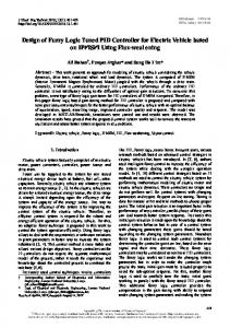
The PID controller is tuned using relay auto-tuning method. The controller parameters are chosen: K=2.01, Ti=0.92, Td = 0.23, and N=10 (filter factor). The actuator output was limited to 1. The step response without compensation the integrator windup is shown in figure 3.
The obtained results represent the effects of integrator windup for different step inputs (unit step, 0.9, 0.7, and 0.5). The effect of windup is clear when the step input is closed to the actuator limit value (0.9 case).
1
The obtained results show that the overshoot and settling time is reduced and affirm the potential of the proposed methodology. The simulation work is extended to test the system behavior to reject rapidly the disturbance signal. The next figure shows the reaction of the PID controller only. The disturbance signal is applied at the instant 6 sec. Its value is constant and equal to (–0.1). The controller takes 3 seconds to reject the disturbance.
step=0.9
0.8
step=0.7
0.6
1
step=0.5
0.4
0.8
0.2
step=0.7
0.6 time in sec.
0 0
2
4
6
8
10
12
Fig.3 Step response (integrator windup)
0.4 0.2
The next figure shows the step response using fuzzy anticipation for the same above conditions. The fuzzy block is built in MATLAB 5 using the fuzzy toolbox. It is so easy to define the inputs, outputs, membership functions and rules using the fuzzy editor. The membership functions are chosen triangular in form. Inputs and outputs are normalized in the range (-1 Æ 1). Then, to simulate the complete system, the fuzzy inference file is linked with the block diagram in SIMULINK.
time in sec. 0 0
2
4
6
8
10
12
Fig. 5 Disturbance rejection (PID)
1 1
0.8
step=0.9
0.8 0.6
step=0.7
0.6
step=0.5
0.4
step=0.7
0.4
0.2 timeinsec.
0.2
0 0
time in sec. 0 0
2
4
6
8
10
Fig. 4 Step response (PID + Anticipation)
2
4
6
8
10
12
12
Fig. 6 Disturbance rejection (PID + Anticipation)
Figure 6 shows the system response using PID with fuzzy anticipation to reject the same disturbance signal. The controller takes less time to retain the desired output. This result affirms the potential of the proposed methodology to reject rapidly the strong and fast disturbances.
5. CONCLUSION In this paper, a self-autonomy PID controller is proposed. The controller consists of two blocks: the former is a classical PID controller tuned around the nominal operating point, while the second one is a feed-forward fuzzy anticipation block. The fuzzy anticipation is used to treat the windup problem when the actuator saturates and also to reject rapidly the disturbance signals. Therefore, the overall system behavior can be improved in acting on signal processing of PID outputs rather than to adapt its parameters. The proposed methodology is verified through simulation on a numeric example. The simulation is carried out using SIMULINK in MATLAB 5 . This environment is very useful to elaborate the fuzzy logic toolbox in simulation. The obtained results affirmed the potential of the proposed methodology.
REFERENCES [1] K. J. Astrom and J. Hagglund, “Automatic Tuning of PID Controllers”, Instrument Society of America, 1988. [2] S. Omatu, M. Khalid and R. Yusof, ”Neuro-Control and Its Applications”, Springer-Verlag London Limited, ch(3), 2nd printing 1996. [3] C. Bohn and D. P. Atherton, “An Analysis Package Comparing PID Anti-windup Strategies”, IEEE Control Systems, Vol. 15, no2, PP.34-40, April 1995. [4] L. A. Zadeh, “Fuzzy sets”, Inform Contr., Vol.8, pp. 338-353, 1965. [5] S. Dutta, “Fuzzy Logic Applications”, Technological and Strategic Issues, IEEE Trans. On Engineering Management, Vol. 40, no 3, pp. 237-254, 1993. [6] C. Von Altrock, “Fuzzy Logic and Neuro Fuzzy Applications Explained”, Prentice Hall Inc. 1995.