and stream processors by implementing data-intensive applications. .... TECHNIQUES. In this section, three benchmark applications are described. Also, ..... Distributed Processing Symposium, San Francisco, CA,. 2000. [17] Xilinx,.
PIM- and Stream Processor-based Processing for Radar Signal Applications Jinwoo Suh and Stephen P. Crago University of Southern California/Information Sciences Institute 3811 N. Fairfax Drive, Suite 200, Arlington, VA 22203 1-703-248-6160
{jsuh, crago}@isi.edu ABSTRACT
some applications.
The growing gap in performance between processor and memory speeds has created a problem for data-intensive applications. Recent approaches for solving this problem are processor-inmemory (PIM) technology and stream processor technology.
Processor-In-Memory (PIM) technology is a promising method for closing the gap between memory speed and processor speed for data intensive applications. PIM technology integrates a processor on a chip that uses DRAM technology. The integration of memory and processor on the same chip has the potential to decrease memory latency and increase the bandwidth between the processor and memory. PIM technology also has the potential to decrease other important system parameters such as power consumption, cost, and area. The V-IRAM chip [5] is a PIM research prototype being developed at the University of California at Berkeley. The V-IRAM contains one vector-processing unit and 8 Mbytes of DRAM in addition to a scalar-processing unit. There is a 512-bit data path between the processing units and DRAM. The target processor speed is 200 MHz, which will provide a peak performance of 3.2 GOPS (Giga Operations Per Second).
In this paper, we assess the performance of systems based on PIM and stream processors by implementing data-intensive applications. The implementation results are compared with the measured performance of conventional systems based on the PowerPC and Pentium processors. The results show that the performance of systems based on these processors is improved up to 70 compared with conventional systems for these data-intensive applications.
Categories and Subject Descriptors C.4 [PERFORMANCE OF SYSTEMS]: Design studies, Performance attributes.
General Terms Algorithms, Measurement, Performance, and Experimentation.
Keywords Vector, Stream, corner turn, coherent side-lobe canceller, beam steering, radar signal processing, V-IRAM, and Imagine.
1. INTRODUCTION Microprocessor performance has been doubling every 18-24 months, as predicted by Moore’s Law, for many years [6]. This performance improvement has not been matched by DRAM (main memory) latencies, which have only improved by 7% per year [6]. This growing gap in performance between processor and memory speeds has created a problem for data-intensive applications. To solve this problem, many methods have been proposed[1][3][9][10][11]. However, these methods provide limited performance improvement or even lower performance for
Another approach for handling the growing processor-memory gap is stream processing. In this approach, the data is routed through stream registers to hide memory latency, allow the reordering of DRAM accesses, and minimize the number of memory accesses. The Imagine chip [4] is a research prototype stream processor being developed at Stanford University. It contains eight clusters of arithmetic units that process data from a stream register file. The target processor speed is 500 MHz, which will provide a peak performance of 40 GOPS. The V-IRAM and Imagine PCB boards are under development at ISI. The V-IRAM board contains one V-IRAM, and Imagine board contains two Imagine chips. In this paper, we assess the performance of data-intensive radar processing applications on the V-IRAM and Imagine processors. We implemented the corner turn, beam steering, and coherent side-lobe canceller (CSLC) applications and measured the performance using cycle accurate simulators. We show that the speedup of the systems based on these processors is up to 70 compared with PowerPC and Pentium-based systems for these applications. The rest of the paper is organized as follows. In Chapter 2, a PIM and a stream processor are briefly described. Also, the systems under development using these chips are presented. Chapter 3 describes three applications we implemented: the corner turn, coherent side-lobe canceller, and beam steerer. Also, the techniques that we used to improve the performance on these platforms are described. In Chapter 4, the implementation results are shown, and Chapter 5 concludes the paper.
Flag units
MIPS
Vector ALUs
Scalar processor
Vector Register File
Memory Unit
Memory Crossbar
DRAM
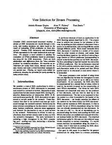
Figure 1. Simplified block diagram of V-IRAM
2. V-IRAM AND IMAGINE 2.1 V-IRAM Processor-In-Memory (PIM) technology is a promising method for closing the gap between memory speed and processor speed. PIM technology integrates a processor on a DRAM memory chip, which uses DRAM technology. In conventional systems, the CPU and memory are implemented on different chips. Thus, the bandwidth between CPU and memory is limited since the data
must be transferred through chip I/O pins and copper wires on a PCB. In a PIM-based system, the integration of memory and processor on the same chip has the potential to decrease memory latency and increases the bandwidth between the processor and memory. The power usage is smaller than traditional processormemory chip pair since it takes less power to drive signals within a chip than between chips. There are several PIM research prototypes being developed. One of them is the DIVA chip[4], which has 8 MB of DRAM and Motherboard Connectors
168-pin SDRAM DIMM Socket
SDRAM
PCI
SysAD
66 MHz
100 MHz
32 bits
76 pins V-IRAM
GT64120 100 MHz 168 pins
Xilinx Virtex-II EEPROM
XC2V1000
Figure 2. Block diagram of V-IRAM board
SIMD/VLIW Control SDRAM
Strea m Regist er File
SDRAM
ALU Cluster ALU Cluster ALU Cluster ALU Cluster ALU Cluster
SDRAM ALU Cluster
SDRAM
ALU Cluster
Figure 3. Block diagram of Imagine 1024 bits of total data path width. A COTS PIM that is currently available is M32R/D [8]. A system using the M32R/D has been implemented at USC/ISI and the results have been reported [16]. In this system, eight M32R/D processors are interconnected using two FPGAs. The IBM Blue Gene project is also investigating the use of PIMs in a high-performance parallel architecture[15]. The Blue Gene architecture is being developed for modeling the folding of human proteins. The Blue Gene project is developing multithreaded PIM processors. The ADVISOR project investigated an algorithmic framework for the design of applications for PIM architectures [11]. The ADVISOR framework models the main characteristics of PIM chips and then, algorithms are designed based on the model. Example algorithms are reported for various applications. The V-IRAM chip [6] is a research prototype PIM being developed at the University of California at Berkeley. The simplified architecture of the chip is shown in Figure 1. The VIRAM contains one vector-processing unit and 8 Mbytes of DRAM in addition to a scalar-processing unit. The vectorprocessing unit contains two arithmetic units, two flag processing units, and two load/store units. These units are pipelined. Different kinds of operations have different number of stages. The functional units can be partitioned into several smaller units, depending on the arithmetic precision required. For example, a functional unit can be partitioned into 4 units for 64-bit operations or 8 units for 32-bit operations. There is a 512-bit data path
between the processing units and DRAM. The DRAM is partitioned into two wings, each of which has four banks. There is a crossbar switch between the DRAM and vector processor. The vector processor supports 91 instructions including arithmetic and vector processing. It also supports special vector instructions that help to obtain high performance on dot-product and FFT operations. The target processor speed is 200 MHz, which would provide a peak performance of 3.2 GOPS. The power consumption is expected to be about 2 W. The block diagram of the V-IRAM board that is being developed at USC/ISI is shown in Figure 2. The board contains a V-IRAM PIM processor, one FPGA for glue logic, and one IF FPGA for the interface with a host computer.
2.2 Imagine Imagine is a stream processing coprocessor that is being developed by Stanford University. The data is read in to the stream registers and sent to the cluster of arithmetic units where the data is processed. The processed data is stored back in the stream registers. The final data is stored in the memory. Figure 3 shows the block diagram of the Imagine. The Imagine multiprocessor board is under development at ISI in collaboration with Stanford. The block diagram is shown in Figure 4. The board contains two Imagine chips, each of which is connected to local SDRAM. Each Imagine is connected to a PowerPC host processor through an FPGA chip. The Imagine chips are connected to a PowerPC host processor through an FPGA chip. The FPGA provides a means of connection between the PowerPC and Imagine by emulating an SDRAM interface on
Interconnection network PCB: Long wires to test long-haul HSTL
HSTL Connector
HSTL Connector
HSTL Connector
Connector
Connector
Connector
Connector
DVI In
DVI Out
Firewire A
Firewire B
HSTL Connector
HSTL Connector
HSTL Connector
Communication FPGA
Host Interface
Processor FPGA
32 bit data, 8 bit addr, control
N Memory
Imagine A
SDRAM: 256MB tot
W S E
Debug Interface
N Memory
SDRAM: 256MB tot
Xilinx Virtex-II
W S E
Imagine B Host Interface 32 bit data, 8 bit addr, control
Xilinx Virtex-II
IDE Connector
SDRAM Interface 8240 Memory bus: up to 100 MHz 64 data
Memory Bus
Host Processor PPC 8240
32 data
DSP Coprocessor TI 6201
PCI
SDRAM: 64 MB tot
SDRAM: 64 MB tot
PCI Connector
PCI
Figure 4. Imagine board
the PowerPC side and an SRAM interface on the Imagine side. It also provides a connection to the DSP chip. The PowerPC also has local SDRAM memory. The PowerPC processor communicates with a host PC through a PCI bus. Applications are compiled on the host PC and sent to the PowerPC through the PCI bus. The PowerPC performs address translation for the PCI memory space, so data written on the PCI memory space by the host PC is actually written on the local memory of the PowerPC. During execution of an application, when the PowerPC encounters kernel code that needs to be executed by an Imagine chip, the PowerPC sends instructions to the Imagine. The Imagine performs the computation and returns the data back to the PowerPC. The board also supports many I/O ports such as DVI, and those are connected to the Imagine chips through another FPGA.
3. APPLICATIONS AND IMPROVEMENT TECHNIQUES In this section, three benchmark applications are described. Also, the techniques used to improve the performance on V-IRAM and
Imagine are presented. For comparison purposes, the C-version CSLC and beam steering codes that are being used for radar systems by Lockheed Martin are used as baselines.
3.1 Corner Turn The corner turn is a matrix transpose operation. The data in the source matrix is transposed and stored in the destination matrix. The matrix size used for this paper, which was chosen to be larger than most caches, is 1024 x 1024 with 4-byte elements. A straightforward implementation of the corner turn using twolevel do-loops is simple, but the performance is degraded significantly due to the strided data accesses. In conventional processor systems, tiling is used to reduce the cost of load-store operations by re-ordering accesses to reduce working set size to better utilize a cache. Since the term “column (row)” is used for both matrices and memories, we will distinguish them by denoting them as “matrix column (row)” and “memory column (row).”
4 rows
Upper half-strip
A strip
Lower half-strip
4 rows
(a) Strips and half-strips
0
1
2
3
4
5
…
N-1
N
N+1
N+2
N+3
N+4
N+5
…
2N-1
2N
2N+1
2N+2
2N+3
2N+4
2N+5
…
3N-1
3N
3N+1
3N+2
3N+3
3N+4
3N+5
…
4N-1
(b) Upper strip
0
N
2N
4
N+4
3N
1
2N+
N+1
3N+
5
2N+1 N+5
3N+1
2N+
2
3N+
6
N+2
2N+2
N+6
2N+
3N+2 3N+
…
4N-1
…
8N-1
(c) Output stream from upper strip
4N
4N+1
4N+2
4N+3
4N+4
4N+5
…
5N-1
5N
5N+1
5N+2
5N+3
5N+4
5N+5
…
6N-1
6N
6N+1
6N+2
6N+3
6N+4
6N+5
…
7N-1
7N
7N+1
7N+2
7N+3
7N+4
7N+5
…
8N-1
(d) Lower strip
4N
5N 4N+
6N 5N+
7N 6N+
4N+1 7N+
5N+1 4N+
6N+1 5N+
7N+1
6N+
4N+2
7N+
5N+2
6N+2
4N+
5N+
6N+
1
N+1
2N+1
7N+2 7N+
(e) Output stream from lower strip
0
N
2N
3N 4N+1
4N
5N
5N+1
6N
6N+1
7N+1
7N 2
(f) Combined strip
Figure 5. Corner turn on Imagine
N+2
2N+2
3N+1 3N+2
…
8N-1
FFT
Sample
Weight
Selection
Calculation
Multiply
IFFT
Interpret
Input Signal FFT
Decimate
(subbanding) Figure 6. Coherent side-lobe canceller The tile size we chose for our corner turn implementation on VIRAM is 16 x 16 element matrix. The selection of tile size depends on the number of vector registers and the memory configuration. In the load operations of our implementation, each column in the tile is loaded into each register in strided mode. Then, the data in the registers are stored as a row in sequential mode. Even though we use the strided loads, the effective performance is as good as the sequential access because of the method described below. When the first column in the tile is loaded, the load operation for each data stalls a few cycles while the memory column is accessed. However, when the second column in the tile is accessed, if the memory columns accessed previously are not precharged, then, the second matrix column can be accessed in one cycle. This is true for the third and all of the remaining matrix columns in the tile. The V-IRAM provides up to eight open columns. Thus, it is possible to keep the columns open when all of the memory columns accessed are in different memory row/wing combinations. Thus, to limit the number of open columns to eight, we first partition the tile into two half-tiles: upper and lower. All data in the upper half-tile is read into the registers before the data in the lower half-tile. Since the size of the upper half-tile is 8 x 16, it is possible to keep all columns open. Also, we need to ensure that the wing-matrix combination does not appear more than once for the half-tile; otherwise, the previously opened column must be pre-charged and performance is degraded significantly. Thus, we used matrix padding to place data in different memory rows and wings. By using this algorithm, the performance of the stride access can be as fast as sequential access. On the Imagine processor, we use the following technique to leverage the streaming capabilities. We partition the matrix into strips of data. Each strip consists of eight rows of data. For each strip, we read the data in the strip and do a transpose. Since the data in the source matrix is 8 x N elements, where N is the number of columns in the matrix, the transposed data is N x 8. The transposed data is stored in the destination matrix. This is explained in more detail in the following paragraphs.
The strip is conceptually partitioned into two half-strips: an upper half and a lower half (see Figure 5). We first perform the corner turn for the upper half-strip ((b) and (c)). We read the four matrix rows and do the transpose using communication units in the clusters. For this operation, four input streams and one output stream are used. Since the rows are read sequentially, there is no performance degradation. The same operation is performed for the lower half-strip ((d) and (e)). Then, the two output streams are read and permuted using the communication unit in the clusters (f). The strip is written into the destination matrix. During the write operation, the unit of data is eight elements and the stride of data accesses is N. When each row in the strip is written, the data is sequentially stored, thus, we can obtain the maximum possible bandwidth. The cycles lost due to the stride mode for the write operation is inevitable since it is a characteristic of DRAM that the pre-charge time is required whenever memory rows are accessed. On Imagine, it is not possible to perform a corner turn by reading eight input streams simultaneously since the current Imagine implementation limits the total number of streams to eight; if eight rows are read, no streams are left for an output stream.
3.2 Coherent Side-Lobe Canceller (CSLC) CSLC is a radar signal processing application used to cancel jammer signals caused by one or more jammers. To cancel jammer signals that appear as side-lobes in the frequency domain, one auxiliary channel is needed per jammer signal. The block diagram of the signal processing is shown in Figure 6. The operations in the upper half of the figure are known as weight calculations and the operations in the lower half are weight applications. To cancel the side-lobe, the weight factor is calculated using the signal from the auxiliary channel. Then, the main signal is partitioned into several sub-bands in the time domain. Each sub-band is then converted to the frequency domain using the FFT (sub-banding). Weight factors are multiplied with the output of the FFT operation to cancel the side-lobe. An inverse FFT is later performed on the output data. Most of the computation time is spent on the FFT and IFFT operations. In our implementation, only the weight application is implemented.
Weight Factors
Butterflies - FFT
Weight Factors
Butterflies - FFT
Bit-Reverse
Bit-Reverse
Weight-Application
Weight-Application
Butterflies - IFFT
Butterflies - IFFT
Bit-Reverse (a) Conventional
(b) Bit-reversed weight factors Figure 7. New CSLC implementation
The following parameters are used for the implementation: four input channels, two main channels, and two auxiliary channels. Each channel has 8 K data samples. All computations are done using floating-point precision. The data is partitioned into 73 overlapped sub-bands, each of which contains 128 samples. For sub-banding, a 128-sample FFT is used.
application, and IFFT are performed (N=73 in our implementation). However, in the new algorithm, the number of bit-reverse operations is only one. Therefore, the bit-reverse operation cost is reduced by a factor of 146. This also enables us to eliminate the load-store operations between the FFT, weight application, and IFFT.
To improve CSLC performance, we used several techniques: a combination of radix-4 and radix-2 FFT, hand optimization of assembly code for the FFT operation, reducing the number of bitreverse operations, and eliminating load-store operations between computational stages.
3.3 Beam Steering
Since the majority of computation time on the CSLC is spent on the FFT operation, we improved the performance of the FFT by using the appropriate FFT algorithms for each architecture. On V-IRAM, a radix-4 FFT is used. Note that since the size of the FFT for the CSLC is 128, which is not power of 4, we used three stages of radix-4 FFT and one stage of radix-2 FFT. Since the current version of the V-IRAM compiler does not vectorize the FFT code written in C optimally, we hand-assembled the FFT to obtain the maximum performance using vector instructions. For example, there are instructions that are suitable for the FFT butterfly that the current compiler does not use for the FFT compilation, such as vhalfup, which shuffles data between two vector registers. On the Imagine, as for the V-IRAM, a combination of the radix-4 FFT and the radix-2 FFT is used. We wrote two kernels for radix4 and radix-2 FFT. We used the FFT algorithm that has the input and output pattern that is most suitable for stream processors. After each butterfly operation, the data is exchanged among clusters using a cluster communicator to arrange data appropriately. In addition to the optimization of the FFT itself, we also removed the bit-reverse operations. Instead of bit-reversing the result of the FFT, the weight factors are bit-reversed in the weight application processing. This is shown in Figure 7. The number of bit-operations for the straightforward method is 2N, where N is the number of data sets on which the FFT, weight
Beam steering is a radar processing application that directs a phased-array radar in an arbitrary direction without physically rotating the antenna. Figure 8 shows a one-dimensional beam steering operation. A real system consists of a two dimensional array of antenna elements populated on a plane. In the system, many small antenna elements transmit the signal with different phases. In the figure, each of the three antenna elements transmits a signal with phase shift of d * sin θ between adjacent elements. By choosing phases, the antenna direction can be controlled. The
θ
d
2d sin θ
Figure 8. Beam steering
computation of the phase for each antenna element involves many load, store and arithmetic operations.
70
In our implementation, the following parameters are used. The number of antenna elements is 1608. Each element can direct the signal up to 4 directions per dwell where a dwell is a period. The phase needs to be calculated for each direction. Depending on the signal frequency and temperature, calibration data needs to be incorporated in the calculation of the phases. In our implementation, four calibration bands are processed.
50
Pentium
40
VIRAM
30
IMAGINE
As for other applications, we used hand-vectorization of the main portion of the beamsteering on V-IRAM. Note that the current compiler is still a prototype and it may be able to vectorize these in the future. For the Imagine, a kernel is written that utilize the clusters
4. EXPERIMENTAL RESULTS AND ANALYSIS In this section, the implementation results of the corner turn, CSLC, and beam steering applications are presented. Performance of these applications is estimated using cycle-accurate simulators provided by the V-IRAM and Imagine teams. For comparison purposes, actual measurements of the application performance were taken using a single node of a PowerPC-based multiprocessor system and a Pentium III system. Applicable performance improvement techniques were also applied to these platforms. The PowerPC results are obtained using a PowerPC-based multiprocessor, the CSPI 2741 [2]. Each CSPI 2741 consists of two boards. Each board contains two PowerPC 750 (400 MHz) processors and a LaNAI network interface. The processors are interconnected through a Myrinet network. The gcc compiler is used for compilatopm. The Pentium results are obtained using a PC running the Linux operating system. The CPU in the system is Pentium III running at 733 MHz. The gcc compiler is used for compilation. Table 1. Experimental results
PPC G3 (400 MHz) Pentium III (733 MHz) V-IRAM (200 MHz) Imagine (500 MHz)
Corner Turn (MB/sec)
CSLC (msec)
Beam Steering (msec)
21.0
16.6
3.76 4.74
83.9
32.2
1441.8
2.57
0.31
1199.1
0.77
0.30
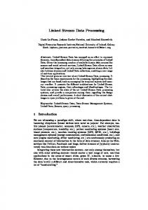
In Table 1, the implementation results of corner turn, beam steering, and CSLC are shown. The speedup is shown in Figure 9. Figure 9 shows that V-IRAM and Imagine provide speedups up to 70 compared with a PowerPC system even though their clock frequencies are not particularly fast. The results show that the V-
PPC G3
Speedup
60
20 10 0 Corner Turn
CSLC
Beam Steering
Figure 9. Speedup IRAM performs better than the Imagine on a corner turn. This is because the V-IRAM has higher bandwidth between memory (which is on-chip on the V-IRAM and off-chip on the Imagine) and the processing unit. However, the Imagine has higher computational performance, which is reflected in the performance of the CSLC, which is more computation-intensive. The V-IRAM and Imagine have similar performance on the beam-steering application because of the balance between memory lookups and computation of that application. In a real system, the current implementation of the V-IRAM may take less space than the current implementation of the Imagine since it has a scalar processor and internal DRAM on-chip and does not need external memory if the application fits in the memory.
5. CONCLUSION We have presented simulated performance results for dataintensive radar processing applications on systems based on the V-IRAM PIM and the Imagine stream processor and compared them to conventional systems. The results show the potential advantages of the new technologies on data intensive applications. We have presented the implementation results of the real-time data intensive applications, coherent side-lobe canceller and beam steering, on both innovative data-intensive systems (V-IRAM and Imagine) and conventional systems (PowerPC and Pentium III). The implementation results show the speedup using these chips provide up to almost 70 compared with the PPC-based system.
6. ACKNOWLEDGMENTS The authors gratefully acknowledge the UC Berkeley IRAM team and the Stanford Imagine team for the use of their compilers and simulators and their generous help. The authors specifically acknowledge Brian Patrick Towles for providing initial idea of the corner turn on Imagine. The authors also acknowledge Rick Pancoast, Steve Shank, Walt Mazur, and Joe Racosky of Lockheed Martin NE & SS for providing the applications. Effort sponsored by Defense Advanced Research Projects Agency (DARPA) through the Air Force Research Laboratory, USAF, under agreement number F30602-99-1-0521. The U.S. Government is authorized to reproduce and distribute reprints for governmental purposes notwithstanding any copyright annotation thereon. The views and conclusions contained herein are those of the authors and should not interpreted as necessarily representing the official policies or endorsement, either expressed or implied, of the Defense Advanced Research Projects Agency (DARPA), Air Force Research Laboratory, or the U.S. Government.
[9] Motorola,
7. REFERENCES [1] C. Conti, D. H. Gibson, and S. H. Pitowsky, “Structural
EC603e Embedded RISC Microprocessor Hardware Specifications, http://ebus.mot-sps.com/brdata/
aspects of the System/360 Model 85, Part I: General Organization,” IBM Systems Journal, Vol. 7, No. 1, pp. 214, 1968.
[10] D. A. Patterson, J. L. Hennessy, Computer organization and
[2] CSP Inc., “2000 Series Hardware Manual S2000-HARD-
[11] M. Penner and Viktor K. Prasanna, “Cache Friendly
001-01,” CSP Inc., 1999.
[3] A. Gupta, J. L. Hennessy, K. Gharachorloo, T. Mowry, and W. D. Weber, “Computative Evaluation of Latency Reducing and Tolerating Techniques,” Proc. 18th Annual International Symposium on Computer Architecture, Toronto, May 1991.
[4] M. Hall, P. Kogge, J. Koller, P. Diniz, J. Chame, J. Draper, J.
design: the hardware/software interface, Morgan Kaufmann, 1994. Implementations of Transitive Closure”, In Proc. of International Conference on Parallel Architectures and Compilation Techniques, September 2001.
[12] S. A. Przybylski, Cache and Memory Hierarchy Design: A Performance-Directed Approach, Publishers, San Mateo, CA, 1990.
Morgan
Kaufmann
LaCoss, J. Granacki, J. Brockman, A. Srivastava, W. Athas, V. Freeh, J. Shin, and J. Park, “Mapping Irregular Applications to DIVA, a PIM-based Data-Intensive Architecture,” Supercomputing '99, Portland, OR, November 1999.
[13] S. Rixner, W. J. Dally, U. J. Kapasi, B. Khailany, A. Lopez-
[5] B. Khailany, et. al., “Imagine: Signal and Image Processing
[14] A. J. Smith, “Cache Memories,” Computing Surveys, Vol.
Using Streams,” HOT Chips 12, Stanford, CA, August 2000.
[6] C. Kozyrakis, “A Media-Enhanced Vector Architecture for Embedded Memory Systems,” Technical UCB/CSD-99-1059, UC Berkeley, July 1999.
Report
#
[7] J. Hennessy and D. A. Patterson, Computer Architecture: A Quantitative Approach, 2nd Edition, Morgan Kaufmann Publishers, Inc., 1996.
[8] Mitsubishi Microcomputers, M32000D4BFP-80 Data Book, http://www.mitsubishichips.com/data/datasheets mcupdf/ds/e32r80.pdf.
/mcus/
Lagunas, P. R. Mattson, and J. D. Owens, “A BandwidthEfficient Architecture for Media Processing,” 31st Annual International Symposium on Microarchitecture, Dallas, Texas, November 1998. 14, No. 3, pp. 473-530, 1982.
[15] M. Snir, “Blue Gene System Overview,” Fourth Annual High Performance Embedded Computing Workshop,” Boston, MA, September 2000.
[16] J. Suh, S. P. Crago, C. Li, and R. Parker, “A PIM-based Multiprocessor System,” International Parallel and Distributed Processing Symposium, San Francisco, CA, 2000.
[17] Xilinx,
http://www.xilinx.com/company/press/kits/pld/ factsheet.htm, 2001.