Platform for Emulating Networked Control Systems in Laboratory Environments Shekar Nethi University of Vaasa Dept. Comp. Science
[email protected]
Mikael Pohjola, Lasse Eriksson Helsinki University of Technology Control Engineering Laboratory
[email protected],
[email protected]
Abstract This paper discusses a platform for prototyping control schemes for networked control systems (NCS). The platform provides tools for simulating various networks in connection with real processes. The paper focuses on an extension to the MoCoNet platform [8], which is a unique environment for monitoring and controlling processes over the Internet in real-time. MoCoNet also provides capability of emulating different networks via network simulation. The platform is extremely valuable for control design in NCS, because the real processes can be first run over simulated networks and different network congestion scenarios can be experimented. This paper extends the MoCoNet system by integrating it with the well known and widely accepted network simulator [9], Ns2. The paper discusses various aspects of this novel integration of Ns2 with realtime operated control systems. The extension allows users of the MoCoNet system to test the control algorithms for NCS with numerous wired/wireless technologies available in Ns2. Furthermore, the paper discusses the development of a simple Java based GUI that is used to create virtual networks in Ns2.
1 Introduction A networked control system (NCS) is a distributed realtime computing and control system [4]. These systems have been and are being researched with great interest, since they provide a cost-effective way of transmitting data from sensors to controllers and onwards to actuators in control systems. There is a high number of these systems implemented in applications such as process control and automotive control systems. The problems in NCS are related to variable transmission time-delays and packet losses that are due to the shared medium and the random retransmission times af-
1-4244-0992-6/07/$25.00 ©2007 IEEE
Riku J¨antti Helsinki University of Technology Communications Laboratory
[email protected]
ter collisions (see e.g. [1], [3]). Such deficiencies are difficult for traditional control algorithms to handle. Often the control algorithms assume constant sampling intervals and do not consider such asynchronic systems. As the interest of automation industry rises towards different networked systems, also wireless communication becomes an option for data transmission in networked control systems. Wireless provides huge opportunities for efficient and flexible measuring in industrial systems, but it also involves some threats that need further research in connection with real process control systems. For evaluating and researching different control algorithms in networked systems, the MoCoNet system [6] has been developed. MoCoNet, abbreviated from Monitoring and controlling laboratory process over Internet, provides a platform to perform networked control experiments with real processes. Besides an easy-to-use graphical user interface the MoCoNet system provides tools for designing and tuning controllers for real case processes in networked control system setup, running real-time control experiments, and using a variety of network simulators to experience the effects of various network technologies in control systems [5], [7]. Managing the experiments and scenario selections are all done over the Internet, and thus the system forms an outstanding remote control environment for both educational and research use. The possibility of conducting experiments with networked control systems via simulating networks makes this remote lab unique and an interesting platform for developing controllers for industry’s needs. This paper extends the MoCoNet properties towards more reliable network simulation as the well known and widely accepted network simulator Ns2 [9] is integrated with MoCoNet. This enhancement offers the capability of simulating wireless networks with real-time control systems. To improve the configuration of the network for experiments, a GUI is implemented for network initialization. The Ns2-MoCoNet integration gives the possibility to expe-
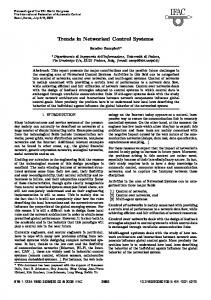
Figure 1. Architecture of the MoCoNet system
rience the effects of a multihop wireless network (e.g. wireless sensor network) with real-time controlled processes. The platform can be further extended with many application layer aspects such as data fusion algorithms. The rest of the paper is organized as follows: Section 2 gives a brief description of the MoCoNet system architecture and its components, and it further presents the proposed integration model. Section 3 gives an introduction to the network simulator emulator (NSE), and presents the communication protocol required and the graphical user interface developed for Ns2 configuration. We also evaluate the usability of our integration scheme for teaching and industrial applications in Section 3 via presenting a simulation example. Section 4 concludes our work.
2 System Architecture Prior understanding of the MoCoNet system is required before presenting the Ns2-MoCoNet integration model. This section provides a brief description of MoCoNet’s various components and defines their specific roles in the system architecture. More information could be found in [6].
2.1
MoCoNet Architecture
Fig. 1 shows the architectural design of the MoCoNet platform. The hardware consists of at least 3 computers (Webserver, RTOS xPC Target and Ns2), an I/O controller board and a router. The number of computers is increased if more processes are added to the system. Usually, one computer is dedicated for controlling each process because then all the processes can be run simultaneously. Currently, there are five processes connected to the system, but only one of them is publicly open for experiments. The number of processes for public use is limited for security reasons.
The system consists of several components and different parts of the system are developed using various tools and programming languages. The control design, for instance, takes advantage of the Rapid Control Prototyping scheme (see e.g. [2]) that implements among other things automatic code generation from control design tools. Here MATLAB and Simulink are extensively used as high level programming tools from which the controller code for realtime execution is automatically generated using extensions of MATLAB. The main components and their functions in the MoCoNet system are described below. Graphical User Interface: For a user, the only visible part of the system is the graphical user interface that is implemented as a Java applet. With the applet the user can connect to the server computer, select controllers and experiment parameters and run the available processes. The process measurements are displayed in real-time in a scope. Webserver, Database, xPC Host: The server computer is responsible for maintaining connections between users and processes, running a reservation system for controlling processes (which user can run which process and when), collecting all the data into a database, and configuring the network simulator. The server side Java programs are connected to MATLAB programs through the MATLAB Web Server (MWS) interface, which is also used for uploading the process control models with tuned controllers into the xPC Target computer. Once the model is uploaded, start and stop messages can be transmitted through the MWS to run the real processes. RTOS xPC Target: Running on MATLAB xPC Target real-time operating system (RTOS), the computer controls the real process or simulates a process in real-time. Equipped with an I/O controller board, the computer measures and controls the process according to the userspecified control algorithms. It transmits signals (i.e. UDP packets) to the network simulator. In order to avoid additional hardware (PCs), controller and measuring unit are implemented physically on the same computer but are virtually distributed over simulated network. Network simulator: Running on SUSE 9.3, has Ns2.30 installed on it, the emulation tool better known as NSE (Network Simulator Emulator) is capable of capturing live packets over Internet. Since the current version provides basic utilities only, the NSE simulator is remodeled to suit the requirements of MoCoNet system. Router: All computers are connected through a network router, which acts as a gateway to Internet.
2.2
Integration Layout
This section explains the proposed Ns2-MoCoNet system integration. Fig. 2 shows the components of the integration model. The process is measured and controlled with
1. User defined TCL script along with mobility and traffic scenario are loaded to the Ns2 computer. The network simulator emulator (NSE) is configured to capture live packets. 2. Using MATLAB Web server tools, the configured executable code for the controller is loaded to the xPC Target computer running the real-time control code, and the controlled process is started (measuring, actuation).
Figure 2. Internal flow structure
• Step 4: Measured signal value is sent on to the network by the xPC Target over UDP packets. The destination for the UDP packet is the controller. • Step 5: NSE, using packet filtering tools, captures the UDP packet on the network. It then performs mapping for the simulated destination (user specified controller/actuator inside virtual network in Ns2). The UDP packet is then injected into the simulated network in Ns2.
Figure 3. Nodes in xPC Target and Ns2 are associated with the UDP port numbers
xPC Target computer equipped with I/O controller board. The measurements are passed through Ns2-simulator emulating the user-specified network. One of the nodes in the network is the process controller that calculates the control signal for the process. This signal is transmitted over the network to the actuator in the process. The sensor and actuator nodes in the real process and the simulated network nodes are associated by their UDP port numbers as depicted in Fig. 3. In this way the real process has a mapping to the network layout in the simulator. Running the system with the process and the network simulator consists of 7 basic steps. • Step 1: (Authentication Phase) Logging into the MoCoNet website [8]. The users are authenticated by username that is mainly used for providing the user his/hers prior data sets, and access to previous experiments and setups. • Step 2: (Modeling and Configuration) Once logged in users configure the controller parameters for the control algorithm and create a virtual network in Ns2. • Step 3: (Loading Files)
• Step 6: Successful reception of the packet inside the simulated network depends on many factors. The destination node could be out of reach, node buffer could overflow or in wireless scenario, nodes could experience harsh channel conditions. If the packet is received successfully by the intended simulated destination, the packet is then sent back to the xPC Target via network, again performing destination mapping (destination UDP port number is changed). The MoCoNet server, checks for the packet’s destination port number which determines if the packet is for the controller or actuator. 1. In the case the packet is for controller, required action information is sent back to the actuator via the network and Step 5 continues, 2. If the packet is destined to the actuator, then appropriate action is taken. • Step 7: The simulation stops, when the user defined Simulation end time is reached or user’s access time is exceeded.
3 Network Simulator Emulator Network simulator [9], Ns2, is a discrete event based simulator, widely accepted de facto standard for simulating wired and wireless networks. With active research on Ns2, contributions for new technologies are quickly available in Ns2. Network simulator emulator (NSE) is an extension to Ns2, it provides basic utilities to read/write live packets from/to the network. Fig. 4 represents the emulation model implemented in NSE.
Table 1. TCL Script # Configuration for the Entry node & Comments set tap1 [new Agent/Tap]; # Create the TCPTap Agent set bpf1 [new Network/Pcap/Live]; # Capture live packets set dev [$bpf1 open readonly eth0]; # Create a BPF and attach it to Ethernet interface 0 $bpf1 filter ”src 130.233.158.170 # Packet filtering options and src port 14469” $tap1 network $bpf1; # Connect BPF to TCPTap Agent $ns attach-agent $node (1) $tap1; # Attach TCPTap Agent to the Ns2 simulated node 1
Figure 4. NSE: Internal Flow Diagram
3.1
Network Simulator Emulator Components
The components of the Network Simulator Emulator (NSE) are listed below. Realtime scheduler: The function of Realtime scheduler is to connect event time inside Ns2 simulator to real-time. TapAgent: The tap agent injects live packets captured into the simulated network in Ns2. A common header is attached with arbitrary packet fields for the simulated packet. The packet type field is P T LIV E to indicate live network captured packet. It is also responsible for writing packets onto the network interface. Network objects: Three network objects are currently supported in NSE, Pcap/BPF, raw IP and UDP/IP. We have remodeled the code for Pcap/BPF to support MoCoNet system requirements. Based on Libpcap, Pcap/BPF enables us to capture live packets from the Ethernet interface at link layer (promiscuous mode). BPF stands for Berkeley packet filter, it provides sufficient packet matching commands, which are extensively used in our proposed integration, and it allows us to distinguish between packets coming from various processes and assign a mapping to the intended destination in Ns2. An example of a TCL script is given in Table. 1. Two Ns2 nodes (node 1 and node 2) are configured to read/write live traffic. The flow is unidirectional with node 1 being the entry point of the live packet and node 2 being the exit node i.e. the gateway node that sends the packet back to the real network. The script uses TapAgent with Pcap/BPF network object for the entry node. The Berkeley packet filter is set to capture packets with IP address 130.233.158.170 with UDP source port 14469 while all other network traffic is ignored. ’readonly’ specifies one-
# Configuration for the Exit node & Comments set tap2 [new Agent/Tap]; # Create a TCPTap Agent set ipnet2 [new Network/IP]; # Create a Network Agent $ipnet2 open writeonly; # in write only mode $tap2 network $ipnet2; #Connect network agent to tap agent $ns attach-agent $node (2) $tap2; #Attach agent to the Ns2 simulated node 2 # Establish Connection & Comments $ns connect $tap1 $tap2; Connect Source to the Sink way traffic, but we could also use ’readwrite’ to associate a node with an exit. Finally, the TapAgent is attached to node 1 in Ns2. The same follows for the Exit node, the network object is IP, the exit node is attached to node 2 and the connection is established.
3.2
Technical Details
The Ns2 server consists of two main components, namely Ns2Control and Ns2Command servers. Ns2Control server enables control of the Ns2 simulator. The Ns2Control server is controlled by the MoCoNet server, so that only legitimate users can connect to the Ns2Command server, which handles the user commands to e.g. start and stop the Ns2 simulator. In order to make proper security policies, authentication to the server is given much importance. The access to the MoCoNet system is restricted by the Ns2Control server interface. When a user has requested and granted control of the Ns2 simulator, the Ns2Command server is started and the user can connect to it. Further, he must authenticate himself with the password received for the MoCoNet server, before any other commands are executed. The steps to use the Ns2 simulator are as follows: 1. The user requests for the Ns2 simulator by the NetworkSettings command sent to the ProcessServer,
Table 2. MoCoNet protocol messages used for MoCoNet server and Ns2Control server communication Command
SetCurrentUser
ReleaseUser
Parameters
processID passwd
processID
Description
Informs the Ns2 simulator that a new user with the given Password has permission to control
Informs the Ns2 simulator that the user has lost the control permission.
Answer
Empty answer, indicating that the command was performed
Empty answer, indicating that the command was performed
which is part of the MoCoNet server. 2. The MoCoNet server selects a password for user identification and informs the Ns2Control server about it by the SetCurrentUser command. The user receives the answer with the password. The commands used in communication between MoCoNet and Ns2Control servers are listed in Table 2. 3. The user then connects to the Ns2Command server with proper authentication. 4. The user loads the TCL file with the NewTCLFile command to be used in Ns2 simulator. 5. Other setup commands are then performed, such as Ns2Traffic and Ns2Mobility (see Table 3 for details). 6. The user starts the Ns2 simulator with the StartNs2 command. 7. The Ns2 simulator is stopped with the StopNs2 command. 8. When the user has run the process and the control of it is released, the Ns2Command server and the Ns2 simulator are shut down. The MoCoNet server will automatically shutdown the Ns2 simulator if the user releases or looses the control of the process. The MoCoNet server has an Ns2Connection class, similar to the MatlabConnection class that handles the connection to the Ns2 computer. The Ns2 system is controlled by the Ns2Control class, which handles control
commands from the MoCoNet server. The user can command the Ns2 computer with an xml style protocol through the Ns2Command functionalities. Ns2Control and Ns2Connection use MoCoNet protocol messages to communicate. The Ns2 command protocol is described in next section.
3.3
Communication Protocol
With proper credential (i.e password), a user can access Ns2 server. An xml style protocol is used to transfer TCL script to the Ns2 computer and trigger the NSE simulator. The format of the command flow is illustrated below. Table 3 explains the elements used in the command protocol and the corresponding actions taken. Not all elements are required in a communication process. The user must always authenticate with the < Authenticate/ > tag, failing which, the following commands are not to be executed. The TCLscript field is the actual text of the script. The Ns2Command server parses the xml tags and validates them with a dtd file before executing the commands. If a command is successfully executed it echoes the tag to the user, indicating that the command was successful. If an error occurs an error tag with the error message of the following format is sent: < ERROR > Error message < /ERROR > < N s2 > < Authenticate passwd = ”passwd”/ > < N ewT CLF ile f ilename = ”f ilename” > T CLscript < /N ewT CLF ile > < N s2T raf f ic f ilename = ”f ilename” cla = ”true” > Traffic generation command line arguments or traffic file contents. < /N s2T raf f ic > < N s2M obility f ilename = ”f ilename” cla = ”true” > Mobility generation command line arguments or traffic file contents. < /N s2M obility > < StartN s2/ > < StopN s2/ > < /N s2 >
3.4
Ns2 Client GUI
A graphical user interface (GUI) was developed for network initialization. Using the GUI, users can design the simulated network; define traffic and mobility scenarios with ease. It provides transparency, as users do not require
Table 3. Ns2 command xml tags and corresponding actions Elements
Attributes
Action
passwd
To authenticate the user with the value of the passwd attribute without authentication no command are executed, this is necessary to disable malicious user from taking control of Ns2 server.
Ns2Traffic
file cla
If the cla (Command Line Argument) attribute is true, the content of the tag is the command line arguments for the Ns2 traffic generator. The Traffic generator is run and the results are saved in the given filename. If cla is false the data is saved as a traffic file with the given filename
Ns2Mobility
file cla
The actions for the mobility case are the same as with the traffic command.
Authenticate
StartNs2
Starts the Ns2 simulator.
StopNs2
Stops the Ns2 simulator, if it has not stopped yet. Kills the process.
ERROR
An error has occurred
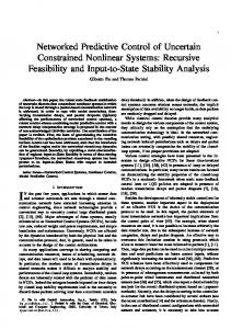
the knowledge of the scripting language (.tcl) used in network simulator. The development version of the GUI is shown in Fig. 5. In Fig. 5, the In and Out indicate the experimented process and controller, while all other nodes are simulated nodes. Arrowed lines indicate the direction of the traffic. The simulations can be performed for wired and wireless scenarios and for mixed network. The network specifications can be saved to disk to an nsfile (with Java serialization) or a TCL-file and loaded easily from the MoCoNet interface. Integrating all features of Ns2 into GUI will take a lot of time. Meanwhile, we have provided option for users to upload pre-written .tcl scripts directly to the Ns2 computer, only after user authentication.
Figure 5. Ns2-Java GUI
Figure 6. The target reference, the control signal driving the process and the process response are shown.
3.5
Usability
This section briefs on the deployment of MoCoNet system in teaching and industrial applications. MoCoNet system can be easily ported to other universities. Components are cheap, most of the software is either free or open source (JDK, MySQL, Linux distribution, Ns2) and most importantly, new processes can be easily integrated to the existing system. The broader picture of the kind of applications MoCoNet supports is Laboratory Resource Sharing. Using Internet as medium of access, universities under bilateral agreements can share laboratory resources. Thus, distribution of laboratory processes among universities, provides a cost effective extension to their existing laboratory resources and further, benefit students to study new laboratory experiments. As an example of the use of the presented Ns2-MoCoNet integration, an event based process monitoring system is demonstrated. The application is process monitoring, where
Table 4. Simulation Results for AODV Routing Protocol
AODV
Figure 7. System model with nodes transmitting process data to the monitoring central
Figure 8. Ns2 model of the process wireless sensors are added on top of the automation system to monitor a complex process. Process faults can be detected or production optimization made with the wireless system. The research topic is to investigate if the wireless network can deliver the required QoS (delay bounds, packet loss threshold) to successfully monitor the system. Since both time-driven measurements and event-driven signals need to be reported to the monitoring central this is a complex task for the network. The process is sketched in Fig. 7 and Fig. 8 shows the corresponding Ns2 model, where all the nodes 0-11 are transmitting data to the monitoring central. The monitoring central communicates with the controllers to steer the process. The distances are so large that multiple hops are needed in communication. In fact all the packets do their last hop between nodes 4 or 5 to the monitoring central. Table 4 presents the performance of AODV routing protocol for the demonstrated example. It can be seen that the congestion at anchor nodes 4 and 5 results in low packet delivery ratio (PDF), i.e unreliable communication. Similarly, other routing protocols could be examined in this framework in order to compare the impact of network protocols on the performance of the monitoring system. In addition, the effects of unreliable communication on system level performance, such as fault detection reliability, could be easily evaluted as the communications are fully integrated with the monitoring system.
PDF(%)
Routing Overhead (Normalized %)
25.09
2.39
Avg End to End delay (sec) 0.022
4 Conclusion and Future work This paper presented an extension to MoCoNet system, which is a platform for experimenting control schemes for networked control systems. The integration with Ns2, the de-facto network simulator, provides numerous possibilities as many of the network protocols are implemented in Ns2 and enables research on distributed systems. Through integration wireless networks can be simulated with high accuracy in connection with real processes and also the impact of network parameters on the control system performance can be studied. The new challenges for control design can be pointed out and the platform offers a possibility of verifying new stability proofs, and control and data fusion algorithms. As an example this paper has demonstrated a wireless factory monitoring application. Automation industries are widely challenged with dynamically changing environments. For instance, in wireless sensor network applications, it is the mobility of the environment which accounts to most link failures. For example, two nodes blocked by a moving crane or trolley could easily cause a link failure (shadowing effect). An extensive simulation study of such wireless network performance in the changing environment is possible using the proposed Ns2MoCoNet integration platform. Similarly, the proposed platform can be used for testing control algorithm performance for industrial applications. There are several pre-defined networks available in the platform that can be easily used for scenario testing. The developed GUI for network initialization and the discussed Ns2 integration give flexible and easy-to-use tools for configuring and modeling the network as closely as possible to correspond to the real industrial applications. The system is open for testing, but currently the usage is limited to certain case process. Nevertheless, any industrial test case would verify the system scalability and usability for industrial applications. Although Ns2 provides an excellent open source platform to develop wired/wireless technologies, even to perform basic simulations, there is a need to learn TCL scripting language, which is not tempting. Other wireless simulation tools such as QualNET and OPNET (which provide free license under university program) have much more friendly user interfaces. Further, extending emulation util-
ities in Ns2, the developed GUI for network initialization though relaxes the difficulty from the system user. This work could easily be extended to develop a full featured network visualization tool for Ns2.
References [1] M. S. Branicky, S. M. Phillips, W. Zhang. Stability of networked control systems: Explicit Analysis of Delay. In Proc. 2000 American Control Conference, Chicago, USA, pp. 2352 - 2357, 2000. [2] V. H¨oltt¨a, L. Palmroth, L. Eriksson. Rapid Control Prototyping Tutorial with Application Examples, Sim-Serv - Virtual Centre for Simulation, www.sim-serv.com, 2004. [3] B. Lincoln. Dynamic Programming and Time-Varying Delay Systems, Ph.D. thesis, Department of Automatic Control, Lund Institute of Technology, 2003.
[4] J. Nilsson. Real-time control systems with delays, Ph.D. dissertation, Lund Institute of Technology, 1998. [5] M. Pohjola. PID controller design in networked control systems, Master’s Thesis, Helsinki University of Technology, 2006. [6] M. Pohjola, L. Eriksson, V. H¨oltt¨a, T. Oksanen. Platform for Monitoring and Controlling Educational Laboratory Processes over Internet. In Proc. 16th IFAC World Congress, Prague, Czech Republic, 2005. [7] M. Pohjola, L. Eriksson, H. Koivo. Tuning of PID Controllers for Networked Control Systems. In Proc. The 32nd Annual Conference of the IEEE Industrial Electronics Society (IECON’06), Paris, France, 2006. [8] MoCoNet Access, www.control.hut.fi/dev/MoCoNet/, cited on 16th Feb 2007. [9] The Network Simulator, www.isi.edu/nsnam/ns/, cited on 15th Feb 2007.