PLL modeling and verification in a cyclesimulation environment
by G. A. Van Huben T. G. McNamara T. E. Gilbert
Recent advances in technology, computer architecture, and automated design environments have ushered in a new era of computer design in which large complex servers such as the S/390 G5 Parallel Enterprise Server™ can be delivered with times to market once reserved for low-end systems such as single-user workstations and personal computers. Yet, the time to market is inversely proportional to customer demand for reliable and continuously available systems. Therefore, the need exists to build and simulate a complete system which incorporates realistic and accurate behavioral representations for all design components. This paper describes a method for modeling an analog phase-locked loop, interfacing it with digital sequential logic components, and simulating the entire system in a high-performance two-cycle simulation environment. Further discussion demonstrates the role this verification has played in the deployment of an improved design point with a shorter time to market compared to previous generations of S/390 ® CMOS machines.
Introduction The previous four generations of IBM S/390 Parallel Enterprise Servers* set the stage for the migration of mission-critical workloads from the traditional mainframe “glass houses” to the scalable, economic CMOS client/server platform. The introduction of the fifthgeneration S/390 G5 Parallel Enterprise Server shattered the glass by implementing the reliability, availability, and serviceability (RAS) of the S/390* architecture on a CMOS chip set exceeding 1000 MIPS of performance. In order to achieve this, the G5 employs a number of advanced design techniques. For example, comparison of the G5 processor with the remainder of the processor subsystem finds the processor running at twice the frequency and using a different chip technology, while the subsystem runs at a frequency comparable to that of many low-end microprocessors. At the heart of the processor subsystem is a critically balanced, high-performance clock-generation and distribution system. A key feature of the clock system is the use of a single-reference oscillator distributed to every major component in the processor subsystem. Located within each component is the onboard-product clockgeneration (OPCG) function. The OPCG logic consists of programmable latches which control the frequency of the
娀Copyright 1999 by International Business Machines Corporation. Copying in printed form for private use is permitted without payment of royalty provided that (1) each reproduction is done without alteration and (2) the Journal reference and IBM copyright notice are included on the first page. The title and abstract, but no other portions, of this paper may be copied or distributed royalty free without further permission by computer-based and other information-service systems. Permission to republish any other portion of this paper must be obtained from the Editor. 0018-8646/99/$5.00 © 1999 IBM
IBM J. RES. DEVELOP.
VOL. 43 NO. 5/6 SEPTEMBER/NOVEMBER 1999
G. A. VAN HUBEN, T. G. McNAMARA, AND T. E. GILBERT
915
916
network, a phase-locked loop, and a balanced distribution system for delivering the various clocks to the shiftregister latches. In addition to normal system operation, the clock-distribution system also controls the scan operation, which is critical to the system power-on sequence. The advanced nature of this design, coupled with the critical time-to-market constraints, mandated verification of the entire clock-distribution system before tape-out. Although prior S/390 systems used varying degrees of simulation on different parts of the clockdistribution system, the G5 was the first to attempt consolidation of the entire clock system into a systemlevel cycle-simulation model. Figure 1 shows a high-level diagram of the clock distribution for six major components of the G5 subsystem: the central processor (CP), the cryptographic subsystem, the system controller (SC), which contains the shared Level 2 cache and interfaces to main memory, the memory bus adapter (MBA), which interfaces with the I/O subsystem, the main memory, which uses card-on-board technology, and the system clock chip. As shown in Figure 1, each major component of the G5 subsystem uses a phase-locked loop (PLL) to synchronize all communication within the system. The benefits of utilizing a PLL-based clock distribution for the high-frequency
G. A. VAN HUBEN, T. G. McNAMARA, AND T. E. GILBERT
synchronous G5 server is obvious once one understands the complexity of designing this high-performance machine. The G5 system employs a variety of packaging technologies, including single-chip modules (SCMs), multichip modules (MCMs), cards, and boards. The distribution of a reliable, low-skew, high-frequency clock signal throughout these various package technologies is difficult at best. The PLL-based design facilitates distribution of a relatively low-frequency reference oscillator to each of the components in the processor subsystem. Each component contains a PLL, which then multiplies that frequency to the higher frequency that it requires while maintaining proper phase alignment for a synchronous design. The ability of the PLL to multiply the reference oscillator frequency is critical, since the G5 system has a number of components running at different frequencies. The CP chip runs at the fastest frequency (eight times faster than the reference oscillator), while the SC, MBA, and main memory run two times slower than the CP (four times faster than the reference oscillator). Another advantage of this design concept is that it permits the use of programmable ratios among a collection of system components. The cryptographic subsystem has been designed to run four or five times slower than the CP. If the cryptographic coprocessor chips were actually to run significantly faster or slower, the multiply bits of the cryptographic PLL could be reprogrammed with a new “gear ratio.” Since the frequency changes are physically isolated from one another, the higher-level packages (such as the MCM, cards, and board) need only maintain proper distribution of the reference oscillator. As long as the on-chip clock logic is capable of supporting a different frequency, the system ratios can be dynamically reprogrammed without the risk of introducing frequencysensitive anomalies into the rest of the system. Finally, because the G5 is a synchronous system, it is critical to keep the clock skew between the various system components very low. Returning to Figure 1, we see that the PLL for each component phase-aligns its on-chip clock distribution with the common reference clock that arrives at each PLL independently of the on-chip clock distribution delay. This delay can vary significantly, since the G5 system comprises chips from different technologies (CMOS 5X, 6S2, and 6X) and the chips have different die sizes. Furthermore, since yield sorting plays an important role in the manufacturing of the G5, and parts of the system are cooled while other parts are not, the phasealignment attribute of the PLL is critical in allowing these various components to communicate synchronously with each other at these high frequencies.
The need for improved PLL simulation Historically, S/390 has relied on cycle simulation as the primary means of functional verification of the hardware.
IBM J. RES. DEVELOP.
VOL. 43 NO. 5/6 SEPTEMBER/NOVEMBER 1999
Since the vast majority of the processor subsystem contains digital logic and SRAMs, it permits the creation of a system-level model comprising one or more processors (CPs), the system controller (SC), various main memory configurations, the memory bus adapter (MBA), the system clock chip, and even the cryptographic subsystem. Final verification typically involves exercising all of these components in several configurations and modes of operation, including power-on reset, logic builtin self-test (LBIST), array built-in self-test (ABIST), initial millicode load (IML), and mainline system operation. With the advent of the G4 Parallel Enterprise Server, the S/390 cycle-simulation methodology was enhanced to include two-cycle simulation in order to verify the actual gate-level design [1]. However, throughout the evolution of the S/390 cyclesimulation methodology, the phase-locked loop function was always excluded. In its place was a very simplistic macro, which created a constant and (always) correct reference clock for distribution to the latches. During the engineering debug of the G4 hardware, a problem was found in the way the OPCG logic was interacting with the PLL. Analysis determined that inclusion of an accurate PLL behavior in the system-level simulation model could have detected the problem. At the beginning of the G5 program, the postmortem of the G4 problem prompted further reviews, which disclosed several potential design escapes that could be verified with an accurate PLL representation in the model. The first item on the list of potential problems was the G4 escape. This problem was related to the OPCG logic, which controls the PLL during the initial stages of powering-on the machine. The design of the G4 and G5 machines is such that each PLL in the system must successfully lock onto the reference oscillator and distribute a multiplied output to that portion of the OPCG logic that is responsible for generating a pair of scan clocks. One of the key functions of the clock-distribution system is to control the scanning of the shift-register latches (SRLs) in all of the chips. This scan operation is the means by which the machine’s registers are initialized to a known state during the power-on reset (POR) sequence. In contrast to earlier generations of the S/390 CMOS machines, the PLLs in the G5 play a direct role in the scan operation. The local PLLs generate the on-chip oscillator, which drives the clock-distribution circuitry that creates a pair of scan clocks. The first scan clock ingates a data bit into the L1, or master, half of the SRL, followed by a second, out-of-phase scan clock which transfers the data bit into the L2, or slave, portion. The relationship between the L1 scan clock and the data bit is crucial, since a misaligned L1 clock could cause unstable data to be captured into the master latch. Furthermore, since all of
IBM J. RES. DEVELOP.
VOL. 43 NO. 5/6 SEPTEMBER/NOVEMBER 1999
the chips in the machine scan in parallel, it is imperative that all of the scan clocks be properly phase-aligned. Thus, if just one chip in the processor subsystem contains a design error that impedes its PLL from establishing the necessary phase alignment with the data bit, it could render the machine incapable of a successful power-on reset. Figure 2 depicts the interaction between the PLL and the OPCG logic responsible for the scan operation. The range and multiply inputs of the PLL are controlled by a series of nonscannable L3 latches. These L3 latches are loaded from a multiplexor whose source is either a set of tied inputs or a set of scannable SRLs. The selection of the multiplexor is controlled by signals from the system clock chip. When the machine first powers on, the PLL must run in bypass mode to initialize the internal circuitry to a known good state. In addition, the PLL bypass signal also controls the loading of the nonscannable latches. Upon exiting bypass mode, the PLL will attempt to lock using the range and multiply settings. Once the PLL successfully locks, a signal is returned to the clock chip. Since the initial state of the scannable SRLs is undetermined at this time, the system clock chip selects the leg of the multiplexor whose inputs are tied. The inputs are tied (either to the supply voltage or to ground) in the proper arrangement to cause the nonscannable latches to be loaded with safe range and multiply values. Once the PLL initialization is complete, the bypass signal goes inactive, which in turn locks the range and multiply bits into the nonscannable latches. At this point, the range and multiply bits begin driving the PLL to produce an output, which is distributed to the scan-clock generator. The scan-clock generator uses the PLL output to create a
G. A. VAN HUBEN, T. G. McNAMARA, AND T. E. GILBERT
917
918
pair of latch and trigger-scan clocks, which control the shifting of scan data bits into all of the system latches under the control of the system clock chip. Once all of the latches (including the scannable SRLs in front of the PLL) are initialized, normal system operation can begin. Normal system operation can continue using the default values loaded into the nonscannable latches, or the system clock chip can invoke a sequence which transfers the programmable range and multiply values from the scannable SRLs into the nonscannable latches. This ability to reprogram the machine to run at different frequency ratios or ranges is especially valuable in dealing with the sorting anomalies associated with new chip technologies. In the case of the G4, an escape occurred because of an unexpected inversion in the PLL bypass signal. As a result, the nonscannable L3 latches were unable to lock in their values when the PLL exited bypass mode. This failure to secure the values into the latches meant that with every pulse of the scan ring, the range and multiply bits in the PLL were switching, thus causing the PLL to unlock, potentially making the machine unscannable. This type of problem, along with other faults such as incorrect ties at the input of the multiplexor and errors between the PLL output and scan-clock generators, served as a sufficient rationale for emulation of the PLL in a system simulation model. Once the machine is successfully initialized, mainline system test can begin. Since the processor operates at twice the frequency of the rest of the processor subsystem, two areas related to these multifrequency interfaces were identified as potential test-floor escapes. The first involved a synchronization signal between the processor and the storage subsystem, which alerts the processor to the correct clock cycle for launching data to and capturing data from the system controller (SC). This synchronization signal originates in the processor’s clock-generation logic and is derived from the PLL output. A design error in the synchronization logic could result in the processor operating 180 degrees out of phase with the storage subsystem. The second area focused on the clockdistribution logic responsible for providing the multiplication controls which determine the frequency that each on-chip PLL must supply. In both cases, improper interaction between the PLL and the rest of the clockdistribution system could severely hamper hardware debugging. Incorporation of an analog component such as a PLL into a digital simulation environment is typically done using mixed-signal simulation techniques. This usually requires the analog components to be described using an analog hardware description language (AHDL) such as VHDL-A. Many electronic design automation (EDA) vendors offer mixed-signal simulators which exercise the analog behaviors in parallel with the digital components
G. A. VAN HUBEN, T. G. McNAMARA, AND T. E. GILBERT
and synchronize them in the time domain. Until recently, these mixed-signal simulators were relegated to small or simple designs because their event-driven nature throttled the overall throughput. However, recent advances in algorithms have enabled mixed-signal simulators to break new ground in the VLSI verification arena. Sony successfully employed mixed-signal simulation in the verification of a PRML controller which comprised 12 000 analog transistors and 10 000 gates [2]. Despite all of these recent advances in the EDA industry, S/390 processor subsystems are so large and complex that they mandate the use of very-high-speed cycle simulators. Beginning with the S/390 G4, twocycle simulation was introduced into the verification methodology. This type of simulation allows the gatelevel design to be exercised on the same high-speed cycle simulator used for functional verification of the registertransfer-level (RTL) design. A typical S/390 system-level model contains hundreds of thousands of SRLs and memory elements, which must be exercised for millions of cycles to achieve a meaningful amount of real-time system operation. Although the use of mixed-mode simulation would permit a far more realistic representation of the PLL, it could only be done at the expense of unacceptable overall performance degradation. Another approach would have been to build a smaller mixed-signal simulation environment comprising only the digital components that interact with the PLL, but this had two drawbacks. First, time and resources would have had to be spent establishing such an environment, since no portion of the existing S/390 verification process utilizes mixed-mode simulation. Second, the overall system-simulation model is also used to verify the firmware and the millicode responsible for power-on reset. The incorporation of more realistic PLL behavior into this model could assist in detecting firmware or millicode errors while awaiting the arrival of the hardware.
VHDL description of the PLL Inclusion of the PLL in the S/390 two-cycle simulation environment meant that a VHDL description had to be written to behave properly in a cycle-simulation environment, yet emulate the PLL with sufficient accuracy. For example, a real PLL relies heavily on feedback loops to achieve proper phase alignment. Unfortunately, feedback loops are not permissible in a cycle-simulation model. With challenges like these in mind, the decision was made to create a VHDL behavior which emulates the PLL without replicating its implementation. In other words, the VHDL behavior maintains the same input/output relationship, but achieves it using a digital method. The obvious disadvantage and risk to this approach is that the test vectors used by the PLL designers for
IBM J. RES. DEVELOP.
VOL. 43 NO. 5/6 SEPTEMBER/NOVEMBER 1999
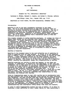
circuit simulation cannot be used to verify the functional equivalence of the PLL VHDL. Because of the absence of any formal way to verify the VHDL, coupled with other resource constraints, a further decision was made to support only a subset of the entire PLL function. By starting out simply, the VHDL could be independently simulated and the results manually verified using timing diagrams. Figure 3(a) depicts a block diagram of the PLL. The inputs consist of the reference oscillator, the multiply bits, the range bits, the feedback clock, and the bypass signal. The outputs consist of the PLL output and the sync out signal. Figure 3(b) illustrates through timing diagrams how the outputs behave with respect to the reference clock input for various settings of the multiply bits. Two things about PLL emulation should be noted at the outset. First, the PLL used in the G5 has dual outputs, because some chips in the G5 system contain logic running at two frequencies. Since only the primary output (PLL OUTA) is fed back to the input, this output has the only correlation to the reference oscillator. The secondary output (PLL OUTB) is more complicated, since it is proportional to the ratio of the two input range settings. However, difficulties arise in trying to model these ratios in a cycle-simulation environment, since they can be fractional and nonbinary. Thus, for the sake of simplicity, the function involving the range inputs was omitted. Second, the S/390 microprocessor PLL must also drive a special Sync out signal which is used to synchronize the CP with the system controller running at half the processor frequency. Without this signal, the CP would not know whether it was in the first half or second half of the SC clock period, and could therefore launch data at an inappropriate time to be captured by the SC latches. Therefore, it was imperative that this signal be properly modeled. The method chosen for emulating the PLL was to describe a function generator capable of producing the required output waveforms as a derivative of the multiply bits and another key variable, the cycles per reference clock period (CPR period). The CPR period denotes the number of simulation cycles required to equal one period of the reference clock. The period of the reference clock is controlled by the simulation environment because it is determined by the system configuration. For example, a typical system configuration consists of the CP running eight times faster than the reference clock, and the remaining components running four times as fast (8:4:1). However, in order to maximize simulation throughput, it is often desirable to use the least common multiple that maintains the same ratio. Therefore, this same system configuration would actually be simulated using a ratio of 4:2:1, which requires a reference clock period of eight simulation cycles instead of 16. Thus, the CP PLL would
IBM J. RES. DEVELOP.
VOL. 43 NO. 5/6 SEPTEMBER/NOVEMBER 1999
produce an output with a period of two simulation cycles, while the PLLs in the remainder of the processor subsystem would produce a period of four simulation cycles. Although the simulated components are running twice as fast as the “real-life” components, the logical timing relationship between them is still identical, and therefore logic design problems can be uncovered with greater efficiency. Some time was devoted to deciding between two approaches for handling the CPR period. The ultimate goal was to load this value into an internal register where it could drive the core function generator. The original method relied on the simulation application program interface (API) manually loading a precalculated value into the CPR register. At first, this approach seemed advantageous, since it did not require the reference clock to run for a minimal number of cycles prior to activating simulation. However, the timing of when to load this register with respect to the rising edge of the reference clock proved to be prone to simulation escapes. In one case the register was loaded in a manner that produced desirable PLL outputs throughout the system, but actually masked a real design problem. After running with the initial implementation for a while, the first approach was abandoned in favor of a second, and more common, approach of monitoring the reference oscillator for one full period and using VHDL statements to calculate the CPR period. This value is then loaded into the CPR register, where it drives the core function generator beginning with the second reference oscillator period. One additional benefit of this approach is that it allows the reference clock period and multiply bits to be dynamically altered during a simulation run.
G. A. VAN HUBEN, T. G. McNAMARA, AND T. E. GILBERT
919
920
G. A. VAN HUBEN, T. G. McNAMARA, AND T. E. GILBERT
IBM J. RES. DEVELOP.
VOL. 43 NO. 5/6 SEPTEMBER/NOVEMBER 1999
Since the VHDL constantly recalculates the reference oscillator period, the new combination of reference period and multiply bits can be converted into a new output waveform at the beginning of any reference oscillator period. The VHDL code shown in Figure 4 describes the method for calculating the CPR period and locking the PLL. This code presumes a reference oscillator with a 50% duty cycle. Since the G5 simulation environment usually runs the fastest clock using two simulation cycles per period (one cycle high, one cycle low), this assumption is valid. Basically, the input oscillator is monitored, and the rising and falling edges are detected. The cpr cnt q counter begins incrementing at the rising edge. Once the falling edge is detected, the value of this counter is transferred to the fall edge cyc q register, which remembers it until the next falling edge. At the end of the oscillator period, the cpr cnt q counter is loaded into the cpr q latch, which drives the core function generator. The fall edge cyc q latch drives the last sync in signal prior to PLL locking. Once the PLL locks, a combination of registers within the core function generator is used to activate it. The last sync in signal drives all of the latches within the core function generator, and it must therefore be activated at the end of the initial reference oscillator period to ensure that the function generator will “kickstart” properly. Regardless of which approach is used to get the PLL started, the remainder of the emulator works the same. It consists of four main components: the divider, the period generator, the output selector, and the reference clock monitor. The purpose of the divider is to calculate the number of simulation cycles in one half of the desired
IBM J. RES. DEVELOP.
VOL. 43 NO. 5/6 SEPTEMBER/NOVEMBER 1999
PLL output period. The period generator uses this value to determine the number of cycles for which the output must remain high or low before changing state. The algorithm for calculating this value, hereafter known as Tau, is to divide the cycles per reference clock period by the multiply bits, and further divide this in half as follows:
G. A. VAN HUBEN, T. G. McNAMARA, AND T. E. GILBERT
921
Tau ⫽ 共cycles per reference clock period兲/共2 ⫻ multiply bits兲.
922
In a system where the reference clock period requires eight simulation cycles, and the PLL has to run four times as fast, Tau would be equal to 1. This means that the PLL output will change state each simulation cycle. The example shown in Figure 5 can be used to code the divider in simulation environments which support the full set of VHDL language constructs. Unfortunately, the S/390 two-cycle simulation model build process contained a restriction which prohibited the use of certain sequential VHDL process statements such as integer division, so the concurrent alternative shown in Figure 6 was substituted. Although the first approach is more desirable, since it is a general-purpose implementation capable of handling any
G. A. VAN HUBEN, T. G. McNAMARA, AND T. E. GILBERT
combination of frequency ratios, the second approach was more than adequate for the G5 simulation plan. The second major component of the VHDL behavior is the period generator. The VHDL code shown in Figure 7 describes this implementation. The last sync in signal drives each of the registers, which are clocked every simulation cycle. This signal is activated at the very beginning, when the cpr q register is first loaded (either by monitoring the incoming reference clock and calculating its period or by manually loading the register through the simulation API), and each time the period generator believes that the last cycle of the reference clock period has been reached. This signal serves advance notice that the reference period is about to expire, which means that the internal counters must be reset on the next cycle.
IBM J. RES. DEVELOP.
VOL. 43 NO. 5/6 SEPTEMBER/NOVEMBER 1999
Although the two counters appear similar in nature, they do have separate purposes and are both required. The per cnt q register counts the number of output periods produced during one reference clock period. This counter exists to drive the sync out output. The other counter, cnt q, is compared against Tau to determine when to flip the state of the hi lo q register. The hi lo q register drives the PLL output high and low when it is not running in bypass mode. The output of the hi lo q register is sent to the output selector, which is described in Figure 8. The output selector simply selects either the output of the period generator (when running in normal system mode) or the input reference clock (when running in bypass mode). The sync out signal refers to the synchronization signal, which is produced on the CP PLL. It is active during the last PLL output period of the reference clock period. This output drives that portion of the OPCG logic which generates the synchronization signal between the processor and SCE. Another subtle detail is the use of a special register known as the inv pll q latch, whose job is to adjust for 180-degree phase shifts in the clock-distribution network. The PLL output traverses the clock-distribution system and ultimately returns as a feedback clock input to the PLL. In a real PLL any phase misalignment caused by delay in the clock-distribution system will be detected by the phase differentiator and corrected by the voltagecontrolled oscillator. Thus, if an inverter is introduced in the clock-distribution logic, it will appear as a 180-degree delay in phase and will be handled accordingly. In a cyclesimulation environment, the only two possibilities are for the feedback clock to be in phase or inverted with respect to the reference clock. In those functional units where an inversion has been introduced, this latch is set by the simulation API as a means of canceling out the inversion. If for any reason the inversion has disappeared from the clock-distribution network, the reference clock monitor will trigger an error condition requiring investigation. Assuming that the design change is intentional and desired, the simulation environment will flip the state of the latch, and the PLL behavior will be synchronized with the clock network again. The final component of the PLL model is the reference clock monitor. Since the whole premise of this VHDL behavior is to assume the shape of the reference clock based on the combination of the cycles per reference clock period and the multiply bits, a means must exist to validate this assertion. Without it, the reference clock could oscillate wildly, yet as long as the cpr q and mult q registers held legitimate values, the PLL VHDL would continue to produce a desirable output. Therefore, this piece was designed to catch three kinds of errors:
IBM J. RES. DEVELOP.
VOL. 43 NO. 5/6 SEPTEMBER/NOVEMBER 1999
1. A design error in the system clock chip, which results in the failure of the reference clock to oscillate at the proper frequency continuously throughout the simulation. 2. An invalid combination of values in the cycles per reference clock period (cpr q) and multiply bits (mult q), which could result from an unexpected load of these registers at some point in the simulation run. 3. Some problem in the clock-distribution network which prevents the rising edge of the feedback clock from aligning with the rising edge of the reference clock. The pll lock q, described above, serves as the reference clock monitor. As long as the feedback clock has a matching rising edge and the last sync in signal was active on the previous cycle, the period generator is presumed to be synchronized with the reference clock. The simulation environment constantly monitors the pll lock q signal and flags an error condition if this latch ever resets.
Exercising the PLL in the system-simulation environment System simulation of the G4 was performed using a nonfunctional piece of VHDL as a placeholder for the PLL. This meant that the clock chip logic was unable to generate a usable reference oscillator for the chips in the processor subsystem. Therefore, the simulation
G. A. VAN HUBEN, T. G. McNAMARA, AND T. E. GILBERT
923
924
environment employed a macro to override the reference clock input of all of the chips with an artificially generated oscillator. When done properly, this served as sufficient means for verifying the digital OPCG logic; however, since the frequency of each chip had to be controlled by the simulation macro, the possibility existed for a mistake in the simulation environment to mask out a real design problem. Introducing a PLL behavior into the model was done primarily to minimize as much of this exposure as possible. The ideal solution would be a simulation macro which only drives the oscillator into the system clock chip. From that point forward, all reference oscillator and clock signals would be naturally produced by the combination of the real gate-level design and the PLL behavior. Unfortunately, differences in design methodologies and tools prohibited the PLL behavior from being incorporated into the system clock chip. However, it was assimilated into all of the other processor subsystem chips. This liability resulted in the continued use of a simulation macro to generate a reference clock, but now a single reference clock, running at the proper frequency, was deployed to each chip input. The required frequency ratios and system clocks were generated entirely by the design interacting with the PLL behavior. The PLL behavior participated in three aspects of the system-simulation test plan. First, normal system operation was conducted by setting the multiply bits for each PLL and running the system assurance kernel (SAK). The SAK runs small programs which exercise all of the functional units within the processor subsystem, and any problem in the clock distribution network or the CP–SC synchronization logic would likely surface here. The second major area exercised at the system level comprised the various clock functions. These consisted of starting and stopping the clocks to ensure that all of the chips ceased and resumed operation in tandem. Another important task involved switching the machine into several nonmainline modes of operation such as logic built-in selftest (LBIST), array built-in self-test (ABIST), and stop-oncount-or-error (SOCE). All of these modes require the OPCG logic to generate a precise sequence of clocks, and the addition of the PLL behavior to these tests further increased the realism of the verification environment. Finally, specific exercises were performed to verify the setup and initialization of the PLL. One test was designed to run the machine through a self-test sequence, which requires the nonscannable PLL input latches to be loaded from the default inputs of the multiplexor while the PLL is running in bypass mode. Then the PLL was switched into normal system mode, and if the resulting PLL output was driven by the values in the L3 latches, the setup was verified to be correct. The other test verified that different multiply values could be programmed into the scannable SRLs and forwarded to the PLL to dynamically alter the frequencies.
G. A. VAN HUBEN, T. G. McNAMARA, AND T. E. GILBERT
Results and conclusions During the verification process, one task involved manually inspecting the waveforms of the latch and trigger clocks on all of the chips in the processor subsystem, and comparing them to a written specification. The inspection revealed a 180-degree phase mismatch between one of the chips and the spec. A misunderstanding concerning the operation of the PLL behavior resulted in altering of the simulation test case. Although it was not known at the time, this turned out to be an erroneous action which corrected the phase mismatch. Unfortunately, the phase mismatch was due to an extra inversion in the design of the clock-distribution system, and this flaw was released with the initial tape-out. The potential disaster was averted by keen foresight on the part of the lead clock designer. Prior to the advent of the PLL behavior, a scannable latch was implemented in the clock logic to permit the output to be altered by 180 degrees. This binary phase-shifting switch was controllable by firmware and ultimately circumvented the design escape. A postmortem of the G5 system simulation cited several areas for improvement. The foremost improvement was aimed at the cause of the previously mentioned misunderstanding: the mechanism for “kick-starting” the PLL output. This led to the decision to change the PLL behavior from the first approach of manually loading the CPR register to the second approach of monitoring the reference oscillator and calculating the CPR period. Since the simulation environment is no longer required to initialize any part of the PLL, the only remaining causes of incorrect clock distribution are design errors or an error in the PLL VHDL behavior. Additional means are being investigated for verifying the VHDL against the actual circuit design test vectors, and it is expected that this can be implemented on a future design. Future S/390 servers will be designed using a common cycle-simulation process for the entire processor subsystem, which will permit the PLL behavior to be incorporated into the system clock chip. This will remove the need for the simulation environment to override the real reference clock with an artificially generated oscillator. In addition, deployment of a new simulationmodel build process is underway, which may permit sequential VHDL statements such as integer division. If this can be achieved, it will result in a more efficient emulation of the PLL, since the VHDL will be generalized to handle any frequency multiplication. Finally, methods are being examined to emulate the function of the range bits, which are ignored in the current verification process. This is becoming increasingly important, because future S/390 designs will use the dual outputs of the PLL in more portions of the machine. Since the potential for design escapes increases with increasing usage of this function, work is already underway to
IBM J. RES. DEVELOP.
VOL. 43 NO. 5/6 SEPTEMBER/NOVEMBER 1999
improve the VHDL to handle the second set of range inputs. As the complexity of large-system designs and time-tomarket requirements continue to act as opposing forces on the verification process, improved simulation accuracy will be a necessity. Diminishing numbers of designers, working under escalating time pressure, only increase the chances of design escapes into manufacturing. When these design escapes cannot easily be circumvented with a software or microcode patch, the result can be a disastrous delay in product deployment. Hence, a new verification environment is emerging in which no exercise can be considered too trivial for simulation. In such an environment, the use of high-performance cycle simulation to verify the digital, analog, firmware, and software components of these large systems is a desirable means for achieving success. *Trademark or registered trademark of International Business Machines Corporation.
References 1. Gary A. Van Huben, “The Role of Two-Cycle Simulation in the S/390 Verification Process,” IBM J. Res. Develop. 41, 593–599 (1997). 2. K. Ogawa, Yuji Gendai, and Eric Filseth, “Mixed Signal Ics Need Top Down Design,” EE Times, May 13, 1996.
Received January 8, 1999; accepted for publication June 21, 1999
Gary A. Van Huben IBM System/390 Division, 522 South
Road, Poughkeepsie, New York 12601 (
[email protected]). Mr. Van Huben joined IBM in 1986 and is currently an Advisory Engineer. He has held various design assignments involving the S/390 storage controller, central processor, and I/O subsystem. His most recent assignment is overall responsibility for the Level 2 cache and subsystem data flow. In addition to logic design, Mr. Van Huben has also worked on various design processes and methodologies within the S/390 organization, including his present position as technical leader for the data management and design control process governing S/390 hardware design. Mr. Van Huben received his B.S. degree in electrical and computer engineering from Clarkson University in 1986; he currently holds seven U.S. patents, has received three IBM Invention Achievement Plateau Awards, and has authored several technical papers.
Timothy G. McNamara IBM System/390 Division, 522 South
Road, Poughkeepsie, New York 12601 (
[email protected]). Mr. McNamara is a Senior Engineer in S/390 custom microprocessor design. He received his B.E. degree in electrical engineering from the State University of New York at Stony Brook in 1983 and his M.S. degree in computer engineering from Syracuse University in 1990. He is currently working on high-performance clock system designs for the S/390 CMOS microprocessors. Mr. McNamara has authored or co-authored a number of technical papers; he holds three U.S. patents.
Thomas E. Gilbert IBM System/390 Division, 522 South
Road, Poughkeepsie, New York 12601 (
[email protected]). Mr. Gilbert joined IBM in 1974 and has held many technical and management positions. He is currently an Advisory Engineer in IBM S/390 design verification, working on the CMOS clock chip and system integration of the S/390 G5 system. His previous verification experience includes team leader and verification of areas on various S/390 systems and CMOS channels. He has been working in design verification since 1984. Mr. Gilbert received an IBM Outstanding Innovation Award in 1988 for his work on I/O subsystem drivers, an IBM Outstanding Technical Achievement Award in 1990 for his work on scan-ring modeling, and an IBM Team Award for his work on the S/390 G3 common chip verification. Most recently he has received IBM Outstanding Innovation Awards for his clock chip and LBIST verification on S/390 G4 and G5.
925
IBM J. RES. DEVELOP.
VOL. 43 NO. 5/6 SEPTEMBER/NOVEMBER 1999
G. A. VAN HUBEN, T. G. McNAMARA, AND T. E. GILBERT