PHYSICAL REVIEW E 75, 056213 共2007兲
Polarization synchronization in unidirectionally coupled vertical-cavity surface-emitting lasers with orthogonal optical injection 1
M. Sciamanna,1,* I. Gatare,1,2,† A. Locquet,3,‡ and K. Panajotov2,§
Supélec, LMOPS CNRS UMR-7132, Unité de Recherche Commune Supélec et Université de Metz, Rue Edouard Belin 2, F-57070 Metz, France 2 Department of Applied Physics and Photonics, TW-TONA, Vrije Universiteit Brussel (VUB), B-1050 Brussels, Belgium 3 Unité Mixte Internationale 2958 Georgia Tech-CNRS, Georgia Tech Lorraine, 2 Rue Marconi, F-57070 Metz, France 共Received 13 November 2006; revised manuscript received 19 February 2007; published 22 May 2007兲 We analyze theoretically the polarization dynamics in unidirectionally coupled vertical-cavity surfaceemitting lasers 共VCSELs兲. The master VCSEL is subject to an isotropic optical feedback. The slave VCSEL is subject to an orthogonal optical injection from the master VCSEL, i.e., only the linearly polarized mode orthogonal to the dominant linearly polarized mode of the free-running slave VCSEL is injected into the slave VCSEL. This laser configuration may lead the slave VCSEL polarization to switch to that of the injected master laser field. The injected power required for polarization switching depends on the frequency detuning. We identify in the plane of the injection parameters two regions of enhanced synchronization between the injected LP mode and the corresponding slave LP mode. In the so-called region II the slave VCSEL exhibits anticorrelated dynamics in its two LP modes while in the so-called region I the slave VCSEL exhibits dynamics in only one LP mode, which corresponds to the polarization of the injected field. The two regions exhibit different synchronization properties in both the LP mode dynamics and total intensity dynamics. We furthermore analyze the dependency of the synchronization quality on the parameter mismatch between master and slave VCSELs and on the polarization switching properties of each VCSEL. DOI: 10.1103/PhysRevE.75.056213
PACS number共s兲: 05.45.⫺a, 42.65.Sf
I. INTRODUCTION
Vertical-cavity surface-emitting lasers 共VCSELs兲 exhibit several desirable characteristics such as a small threshold current, circular beam profile with narrow divergence, single longitudinal mode emission, wafer-scale testing and array capabilities 关1兴. These great advantages have stimulated their development and use in applications previously reserved for conventional edge-emitting lasers. VCSELs have also attracted considerable attention in reason of their complex polarization properties: the emitted light is typically linearly polarized 共LP兲 along one of two preferential and orthogonal directions 共x and y兲 but the light polarization may easily switch between these two x and y LP modes as the laser operating conditions such as current or temperature vary 关2,3兴. The so-called polarization switching has been the subject of several theoretical and experimental studies for more than 10 years, both for the understanding of the underlying physical mechanism and for the development of polarization control techniques in polarization-sensitive applications; for a review see, for example, Refs. 关4,5兴. Additional complexities in the VCSEL polarization dynamics arise when the laser is subject to delayed back-reflection of the emitted light 共op-
*Electronic address:
[email protected]. Also at Unité Mixte Internationale 2958 Georgia Tech-CNRS, Georgia Tech Lorraine, 2 Rue Marconi, F-57070 Metz, France. † Electronic address: gataregaគ
[email protected] ‡ Electronic address:
[email protected] § Electronic address:
[email protected]. Also at Institute of Solid State Physics, 72 Tzarigradsko Chaussee Blvd., 1784 Sofia, Bulgaria. 1539-3755/2007/75共5兲/056213共10兲
tical feedback兲 关6–8兴, to optical injection from a second laser 关9兴, or to large current modulation in data communications 关10,11兴. These laser configurations can destabilize the VCSEL dynamics into complex time-periodic, quasiperiodic or even chaotic dynamics 关12–16兴, or control the light polarization and lock the VCSEL into a well-defined steady-state polarization dynamics 关9,17–20兴 or stable polarization selfmodulation 关21–24兴. Chaotic VCSELs are highly desirable compact light sources that can be used in chaos-based secure communications 关25–28兴. The idea of chaotic secure communications is to encode a message into a noiselike chaotic emitter and to decode the message by using a receiver that is synchronized to the chaos generated by the emitter. Chaos synchronization has been demonstrated in several laser systems, including Nd:YAG 关29兴, CO2 关30兴, fiber lasers 关26,27兴, and semiconductor edge-emitting lasers 关31–33兴. Experimental demonstration of message encoding-decoding has been shown by several groups and a state-of-the-art report has been given recently by Argyris et al. 关34兴. By contrast, studies on VCSEL synchronization remain scarce. First theoretical studies by Spencer et al. 关35,36兴 have unveiled the possibility to synchronize chaos in coupled VCSELs in master-slave configuration. However, they did not take into account the complex polarization dynamics of VCSELs. Additional more recent theoretical investigations have modeled synchronized coupled VCSELs, however focusing mostly on the total intensity synchronization properties 关37兴. Very recently, first experiments have demonstrated chaos synchronization in VCSELs in either master-slave unidirectional configuration 关38兴 or in mutually coupled configuration 关39兴. The practical use of chaos synchronized VCSELs for secure message transmission has also been tested recently in laboratory 关40兴,
056213-1
©2007 The American Physical Society
PHYSICAL REVIEW E 75, 056213 共2007兲
SCIAMANNA et al.
with successful encoding-decoding of a 200 MHz sinusoidal message. These first experimental studies motivate a new, detailed theoretical analysis of chaos synchronization in coupled VCSELs, which would take into account the complex polarization switching properties and polarization dynamics in VCSELs. In this paper, we analyze theoretically the synchronization properties and polarization dynamics of two VCSELs that are unidirectionally coupled in a master-slave configuration that has been recently investigated experimentally by Hong et al. 关38兴 and Lee et al. 关40兴 The configuration is such that 共1兲 the master VCSEL is rendered chaotic via optical feedback, 共2兲 the master laser exhibits chaos in its two orthogonal x- and y-LP modes, 共3兲 the x-LP mode of the chaotic emitter is rotated to y-LP direction and injected into the slave laser, 共4兲 the free-running slave VCSEL emits almost only the x-LP mode, the y-LP mode being strongly suppressed, and finally 共5兲 the slave laser is only subject to optical injection and not to optical feedback 共such a configuration is also called “open-loop” 关41兴兲. The coupled VCSEL configuration is therefore based on an isotropic optical feedback on the master laser, and an orthogonal optical injection on the slave laser. It is worth mentioning that, besides its applications in VCSEL experiments, a configuration based on polarizationrotated optical injection has also recently received interest in coupled edge-emitting lasers to demonstrate identity synchronization 关42兴. Our theoretical analysis successfully reproduces qualitatively the VCSEL experimental results, that is, coupling light from the master to the slave VCSEL makes it possible to excite the normally depressed y-LP mode in the slave laser and to induce a good synchronization between the y-LP mode dynamics of the slave laser and the chaotic dynamics in the injected LP mode of the master laser. The chaos synchronization between y-LP slave laser mode and x-LP injected master laser mode is furthermore accompanied by an antisynchronization between the x-LP slave laser mode and the x-LP injected master laser mode. The antisynchronization is the result of the anticorrelated dynamics between LP modes in the slave laser. Moreover, our theoretical results unveil features that will motivate additional investigations. Our paper is organized as follows. In Sec. II we detail the rate equation model that has been used for our theoretical analysis of the coupled VCSEL scheme. Section III reports on synchronization properties and polarization dynamics. Two different synchronization mechanisms are reported, and they are mapped in the plane of the injection parameters 共injection rate vs. frequency detuning兲 in Sec. IV. Section IV also analyzes the dependency of the synchronization properties on parameter mismatch between the VCSELs. Section V analyzes the robustness of the synchronization result against modifications of the spin-flip relaxation rate, which is an important but often unknown parameter of the VCSEL model. Conclusions are presented in Sec. VI. II. RATE EQUATION MODEL
The polarization dynamics in each of the two coupled VCSELs is modeled by an extension of the spin-flip model
共SFM兲 关43兴 that accounts for cavity anisotropies, for the isotropic optical feedback in the master laser equations, and for an orthogonal optical injection in the slave laser equations. The parameters of the slave laser are adjusted in such a way that it emits x-LP light when not coupled. The x-LP mode of the master laser is then rotated to the y direction before being injected into the slave laser, i.e., the polarization of the coupled light is parallel to the suppressed LP mode of the slave laser. Our rate equations are dFxM dt
= 共1 + i␣兲共D M FxM + id M Fy M − FxM 兲 − i␥ pM FxM − ␥aM FxM + fFxM 共t − 兲exp共− i M 兲,
dFy M dt
共1兲
= 共1 + i␣兲共D M Fy M − id M FxM − Fy M 兲 + i␥ pM Fy M + ␥aM Fy M + fFy M 共t − 兲exp共− i M 兲,
共2兲
dD M = − ␥e关D M 共1 + 兩FxM 兩2 + 兩Fy M 兩2兲兴 + ␥e M dt − i␥ed M 共Fy M F*x − FxM F*y 兲, M
共3兲
M
dd M = − ␥sd M − ␥ed M 共兩FxM 兩2 + 兩Fy M 兩2兲 dt − i␥eD M 共Fy M F*x − FxM F*y 兲 M
M
共4兲
for the master laser, and for the slave laser dFxS dt
= 共1 + i␣兲共DSFxS + idSFyS − FxS兲 − i␥ pSFxS − ␥aSFxS , 共5兲
dFyS dt
= 共1 + i␣兲共DSFyS − idSFxS − FyS兲 + i␥ pSFyS + ␥aSFyS + FxM 共t − c兲exp关i共 M − S兲t兴exp共− i M c兲,
共6兲
dDS = − ␥e关DS共1 + 兩FxS兩2 + 兩FyS兩2兲兴 + ␥eS dt − i␥edS共FySFx* − FxSF*y 兲, S
S
共7兲
ddS = − ␥sdS − ␥edS共兩FxS兩2 + 兩FyS兩2兲 − i␥eDS共FySFx* − FxSF*y 兲. S S dt 共8兲 Fx,y are the two linearly polarized slowly varying components of the field and D and d are two carrier variables. D accounts for the total population inversion between conduction and valence bands, while d is the difference between population inversions for the spin-up and spin-down radiation channels. The internal VCSEL parameters are as follows: is the field decay rate, ␥e is the decay rate of D, ␥s is the spin-flip relaxation rate 共which accounts for the different
056213-2
PHYSICAL REVIEW E 75, 056213 共2007兲
0.6 0.4
, tot
M
Ctot
(a) Region II
0 −40 1
−10
0
10
20
30
40
−30
−20
−10
0
10
20
30
40
−30
−20
−10
0
10
20
30
40
−30
−20
20
30
40
(c)
S
,y
M
Cx
−20
0.5
S
,y
−30
0.5
0 −40 0.4 S
Region II
(b)
0 −40 1
Cx
Region I
0.2
S
S
S
Ix , Iy , Itot
S
POLARIZATION SYNCHRONIZATION IN…
(d)
0.2 0 −40
−10 0 10 Frequency detuning (GHz)
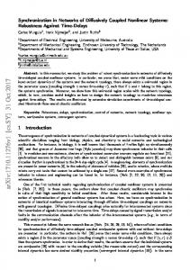
FIG. 1. Evolution of the time-averaged LP mode and total intensities in the slave laser 共a兲, of the correlation coefficient CtotM ,totS 共b兲, CxM ,yS 共c兲, CxS,yS 共d兲 as function of the frequency detuning, for a fixed injection rate = 100 GHz. Parameters are specified in the text.
microscopic mechanisms involved in the homogenization of the carrier spins兲, ␣ is the linewidth enhancement factor, is the normalized injection current 共 = 1 at threshold兲, ␥a is the linear dichroism, and ␥ p is the linear birefringence. The isotropic optical feedback in the master laser equations 共5兲–共8兲 has been included in the same way as in Ref. 关12兴, with M being the optical frequency of the x- and y-polarized modes at the solitary laser threshold in the absence of linear anisotropies. The parameter f is the feedback rate, is the external cavity delay time, c is the propagation delay time between the coupled VCSELs, is the injection rate. The detuning is defined as ⌬ = M − S, where S is the slave optical frequency and is defined in the same way as M . We consider first a case for which all parameters of the master and slave lasers are identical, except for the laser frequencies. We take the following values for the laser parameters: ␥e = 1 ns−1, = 300 ns−1, ␣ = 3, f = 5 GHz, c = 0, ␥s = 50 ns−1, M = 6 rad, = 3 ns, ␥aS = ␥aM = −0.1, ␥ pS = ␥ pM = 8.5 rad/ ns, and M = S = 1.2. With these values of the VCSEL parameters the free-running lasers exhibit a single x-LP mode stationary dynamics.
laser mode to the normally suppressed y-LP slave laser mode and then back to the x-LP mode. We find therefore a detuning interval inside which the slave laser switches its polarization to that of the injected light, and moreover inside which the normally dominant slave laser x-LP mode is fully suppressed. We shall call this region “region I” to emphasize that the slave VCSEL only exhibits a single-mode dynamics 共in the y-LP mode兲. As shown in Fig. 1共a兲 the region I expands from frequency detuning of −22 GHz up to about 20 GHz. Outside region I the slave VCSEL exhibits dynamics in its two LP modes, and therefore we shall call this region “region II.” In region I the total intensity emitted by the slave VCSEL is larger than in region II and depends on the frequency detuning. In region II the total intensity of the slave laser light is kept constant whatever the frequency detuning, which relates to the fact that the intensity in the x-LP mode decreases at the benefit of the increase in the y-LP mode intensity. In region I the total intensity of the slave laser light increases because the slave laser mode emits only in the y-LP mode and the injected light therefore interacts coherently with the slave y-LP mode and supports the y-LP mode intensity. In region II the slave laser dynamics consists of a dominant x-LP mode dynamics interacting incoherently with the injected light and, hence, the slave total intensity is purely the incoherent addition of its two LP mode intensities. An interesting question, motivated by previous studies on chaos synchronization in coupled edge-emitting lasers, is whether the chaotic dynamics of the slave laser, induced by the optical injection, is able to synchronize to the master laser optical chaos. We find that indeed not only the LP mode dynamics but possibly also the total intensity dynamics can be synchronized between master and slave lasers, depending on the injection strength and frequency detuning. In the following we analyze quantitatively the synchronization quality between the intensity time traces by using the following cross-correlation coefficients CxM ,yS, CxS,yS, and CtotM ,totS:
冑具关Ix
CxS,yS =
M
CtotM ,totS =
共t兲 − 具IxM 典兴2典具关IyS共t兲 − 具IyS典兴2典
共9兲
,
具关IxS共t − c兲 − 具IxS典兴关IyS共t兲 − 具IyS典兴典
共10兲
冑具关Ix 共t兲 − 具Ix 典兴2典具关Iy 共t兲 − 具Iy 典兴2典 , S
III. POLARIZATION SWITCHING AND POLARIZATION SYNCHRONIZATION
As a result of the optical feedback, the master laser dynamics exhibits optical chaos in its two LP modes. The master laser x-LP mode is then rotated to orthogonal direction and injected into the slave VCSEL. We show in Fig. 1共a兲 the evolution of the averaged intensities in the two LP modes of the slave laser 共with dots兲 and of the slave laser total intensity 共with circles兲 as we vary the frequency detuning between master and slave lasers and for a fixed value of the injected power = 100 GHz. As we scan the frequency detuning from negative to positive detuning values we can observe a polarization switching from the normally dominant x-LP slave
具关IxM 共t − c兲 − 具IxM 典兴关IyS共t兲 − 具IyS典兴典
CxM ,yS =
S
S
S
具关ItotM 共t − c兲 − 具ItotM 典兴关ItotS共t兲 − 具ItotS典兴典
冑具关Itot
共t兲 − 具ItotM 典兴2典具关ItotS共t兲 − 具ItotS典兴2典 M
. 共11兲
For the coupling configuration considered here, we only observe synchronization of the isochronous type 关44–47兴, which leads to a maximum of the correlation for a time lag equal to c between the intensity time traces. In our case we have chosen c = 0. Anticipating synchronization 关45,48,49兴 is not observed, as could be expected for such a dissymmetric coupling in which we have orthogonal injection of only one of the two LP components. Figure 1 shows the correlation degree between the time traces of the total intensity in master and slave lasers 共b兲, the
056213-3
PHYSICAL REVIEW E 75, 056213 共2007兲
SCIAMANNA et al. 0.6
(a) M
(a)
x
0.5
I
I
x
M
0.4 0.2 0 130
140
145
150
155
0 130
160
0.5
(b)
135
140
145
150
155
160
135
140
145
150
155
160
135
140
145
150 155 desynchronization burst
160
135
140
145 Time (ns)
(b)
I
I
y
y
M
M
0.5
135
0 130
140
145
150
155
(c) I
x
S
x
I
0.2 135
140
145
150
155
Iy
S
0.05 0 130
135
140
145 Time (ns)
150
155
(d)
1 0 130
160
(c)
0 −1 130 2
160 S
0 130 0.1 (d) Iy
0 130 1
160 S
0.4
135
150
155
160
FIG. 2. Time series of master laser and slave laser LP mode intensities, for = 100 GHz and ⌬ = −40 GHz 共corresponding to region II兲.
FIG. 3. Time series of master laser and slave laser LP mode intensities, for = 100 GHz and ⌬ = 0 GHz 共corresponding to region I兲.
x-LP master laser intensity and the y-LP slave laser intensity 共c兲, and between the intensities of the slave laser modes 共d兲, as we scan the frequency detuning and for a fixed injection strength. Interestingly, Fig. 1共b兲 shows that the total intensities in master and slave lasers are badly synchronized in region II 共correlation coefficient very small兲 even though the correlation coefficient CxM ,yS 关in Fig. 1共c兲兴 is close to 1, which implies an almost perfect synchronization between the x-LP injected light intensity dynamics and the dynamics in the slave laser y-LP mode. By contrast, in region I the total intensities of the master and slave reveal a degree of synchronization similar to that existing between the master x-LP and slave y-LP modal intensities, with a maximum correlation coefficient around 0.9. Even though, for the parameter set considered here, the synchronization of the total intensities is better in region I than in region II, the synchronization quality between the master x-LP and the slave y-LP components is better in region II than in region I. This outlines the importance of considering polarization-resolved synchronization. The analysis of the correlation between slave LP mode intensities in Fig. 1共d兲 does not provide clear indication of correlated or anticorrelated dynamics, since the computed correlation coefficient is very close to zero. The cross correlation CxS,yS is not computed in region I since there the x-LP slave laser mode is fully suppressed. Figure 2 analyzes in more detail the time traces of master and slave laser LP intensities, in the synchronization conditions corresponding to region II 共 = 100 GHz and ⌬ / 2 = −40 GHz兲. The comparison between the time traces in 共a兲 and 共d兲 shows that the intensity corresponding to the depressed y-LP mode of the slave laser is almost perfectly synchronized with the injected x-LP intensity of the master laser, with a time-lag equal to c = 0 between the intensity time traces 共as better seen with the reference dashed line兲. The comparison between the time traces 共a兲 and 共b兲, i.e., the time traces of intensities in the LP master laser modes, shows that the LP mode intensities exhibit fast in-phase pulsing but also anticorrelated dynamics on a slower time scale: when one
mode is dominant, the other mode is depressed and vice versa. Such a mode competition with in-phase fast pulsing when the two modes are excited together has been already observed theoretically and experimentally in VCSELs subject to optical feedback 关15,16兴. The comparison between the time traces 共c兲 and 共d兲, i.e., the time traces of intensities in the LP slave laser modes, shows no clear indication of correlated or anticorrelated dynamics on the pulsing time scale, which corresponds to the close to zero correlation coefficient plotted in Fig. 1共d兲. Figure 3 is the same as Fig. 2 but for different coupling conditions 共 = 100 GHz and ⌬ / 2 = 0 GHz兲, corresponding to region I. As shown in panel 共c兲, in this region the slave laser x-LP mode is fully depressed and the slave VCSEL switches its polarization from a normally dominant x-LP light polarization to a now dominant y-LP light polarization. The comparison between the time traces in 共a兲 and 共d兲 shows that the slave laser y-LP intensity dynamics is relatively well synchronized with the injected master laser x-LP intensity dynamics. We observe, however, desynchronization bursts in particular during short time-periods following the switch-off of the injected light. The arrow in Fig. 3共d兲 indicates such a desynchronization burst following the switch off of the x-LP master laser intensity: the y-LP slave laser mode intensity 关in 共d兲兴 exhibits a large pulse before recovering similar pulsing dynamics as in the injected one 关in 共a兲兴. It should also be noticed that the slave y-LP intensity is significantly larger than that of the master laser x-LP intensity, as already illustrated in Fig. 1共a兲. As a result of the partial loss of synchronization, the correlation coefficient taken on average on a long time trace is smaller than that computed for the case of region II in Fig. 2. As for region II, the synchronization occurs with a time-lag equal to c = 0, as better seen with the reference dashed line. In order to further complement the time-series analysis and to emphasize the qualitatively different synchronization properties of regions I and II, we show in Figs. 4共a1兲, 共a2兲 the synchronization diagrams corresponding to Fig. 2 and in 共b1兲, 共b2兲 the synchronization diagrams corresponding to
056213-4
PHYSICAL REVIEW E 75, 056213 共2007兲 Ix , Iy , Itot
S
POLARIZATION SYNCHRONIZATION IN… (a)
S
0.5
S S
, tot
Region I
Region II 0 −40 1
−30
−20
−10
0
10
20
30
40
−30
−20
−10
0
10
20
30
40
−30
−20
−10
0
10
20
30
40
−30
−20
20
30
40
(b)
Ctot
M
0.5
Region II
0
Cx
M
,y
S
−0.5 −40 1 (c) 0.5
−0.4
Cx
S
,y
S
0 −40 −0.2 (d)
−0.6 −40
FIG. 4. Synchronization diagrams corresponding to regions II 关共a1兲, 共a2兲兴 and I 关共b1兲, 共b2兲兴 of qualitatively different synchronization properties: 共a1兲, 共b1兲 IyS as function of IxM , 共a2兲, 共b2兲 ItotS as function of ItotM .
Fig. 3. In 共a1兲, 共b1兲 is plotted the intensity of the slave laser y-LP mode as a function of the intensity of the injected master x-LP mode; in 共a2兲, 共b2兲 is plotted the slave laser total intensity as a function of the master laser total intensity. In the case of injection parameters corresponding to region II, the slave y-LP mode intensity is almost perfectly synchronized with the injected x-LP mode intensity of the master laser, but with the slave laser synchronized y-LP mode intensity much smaller than the injected master x-LP mode intensity. However, the total intensities of the two lasers are almost uncorrelated, as shown in Fig. 4共a2兲 and also pointed out by the computation of the correlation coefficient in Fig. 1共b兲. The fact that the slave laser total intensity is badly synchronized to the master laser total intensity can be attributed to the fact that only the weak LP mode of the slave laser synchronizes very well with the dominant master LP mode. Therefore the contribution of the synchronized slave LP mode dynamics to the slave total intensity dynamics is very small. The synchronization diagram of Fig. 4共b1兲 better shows the desynchronization bursts between the y-LP slave laser intensity dynamics and the x-LP master laser intensity dynamics. In spite of these desynchronization events, the two LP mode intensity dynamics are relatively well synchronized in region I but the synchronization quality is clearly smaller than that observed in region II 关see the comparison between 共b1兲 and 共a1兲兴. Moreover, the comparison between the synchronization diagram of Fig. 4共b2兲 and that of Fig. 4共a2兲 shows that in region I the total intensity dynamics are much better synchronized than in region II, as it was already clear from the computation of the correlation coefficient in Fig. 1共b兲. The previous figures have considered a case of unidirectionally coupled VCSELs but where the two coupled lasers have the same internal parameters, in particular the same linear cavity anisotropies and injection currents. However, it is commonly observed in VCSEL experiments that the polarization switching and polarization dynamical properties are
−10 0 10 Frequency detuning (GHz)
FIG. 5. Same as Fig. 1 but considering mismatch in VCSEL linear cavity anisotropies and injection currents: ␥aM = 0.1, ␥ pM = 6 rad/ ns, M = 1.2 and ␥aS = −0.1, ␥ pS = 8.5 rad/ ns, S = 1.4.
strongly dependent on the device linear anisotropies and operating conditions such as injection current or temperature 关50兴. We therefore consider now different values of the linear anisotropies ␥a and ␥ p for the master and slave VCSELs, as well as different values of the injection current . The VCSEL parameters and operating conditions are chosen such that the polarization properties are qualitatively similar to those used in the recent experiment of Ref. 关38兴. The master laser is simulated with ␥aM = 0.1, ␥ pM = 6 rad/ ns and M = 1.2. The master laser exhibits a polarization switching from x-LP to y-LP mode at about ⬃ 1.3 with bistability. The slave laser is simulated with ␥aS = −0.1, ␥ pS = 8.5 rad/ ns, and S = 1.4. The slave laser exhibits a single x-LP mode up to about = 1.6. In order to analyze the effect of the parameter mismatch on the polarization and total intensity synchronization properties, we plot in Fig. 5 the evolution of the LP mode and total output intensities and the correlation coefficients CxM ,yS, CxS,yS, and CtotM ,totS as we scan the frequency detuning for a fixed injection strength, all other parameters remaining the same as those used for Fig. 1. We still observe in Fig. 5 the existence of two regions of qualitatively different polarization and synchronization properties. In region I, the slave has switched its polarization to that of the injected field and emits only the corresponding y-LP mode. In region II the slave laser exhibits a two-LP mode dynamics. Region II is characterized by an almost perfect synchronization between the y-LP slave intensity and the injected x-LP master intensity 关see Fig. 5共c兲兴, with a correlation coefficient very close to 1. However in region II the total intensities of both master and slave VCSELs are almost uncorrelated 关see Fig. 5共b兲兴. In region I the synchronization between y-LP slave laser intensity and x-LP master laser intensity is much weaker than that observed in region II, with a maximum correlation coefficient close to 0.5. In region I the total intensities of the two VCSELs synchronize as badly as do the corresponding polarization modes 共maximum correlation coefficient close to 0.5兲, however the synchronization between total intensities is much better than the one observed in re-
056213-5
PHYSICAL REVIEW E 75, 056213 共2007兲
SCIAMANNA et al.
IV. MAPPING OF CORRELATION COEFFICIENT
The preceding section has unveiled two synchronization mechanisms in our coupled VCSEL problem. One corresponds to region I in which the normally depressed y-LP slave laser mode synchronizes with the injected x-LP master laser mode, while the slave x-LP mode is completely suppressed by the orthogonal injection. The second corresponds to region II in which the slave laser exhibits a two-mode dynamics, with a depressed y-LP mode almost perfectly synchronized with the injected x-LP master laser mode and with anticorrelation between the slave laser LP mode dynamics. We analyze in Figs. 6 and 7 the dependency of the CxM ,yS and CxS,yS correlation coefficients, respectively, on the coupling parameters: injection rate and frequency detuning ⌬ / 2. A color map is used in each case and plotted on the right of the figure. The maximum injection rate is chosen such that it corresponds to a realistic value for VCSEL devices. Indeed we can write = r共1 − r2兲text / 共rin兲, where r is the amplitude reflectivity of the VCSEL output mirror, text is the amplitude transmissivity in the path between the coupled VCSELs, and in is the intracavity round-trip time. In the optimal case for which there is no attenuation in the path between coupled VCSELs, i.e., text = 1, taking r = 0.995 and
300 0.9
250
0.8
Injection rate (GHz)
0.7
200 0.6 0.5
150 0.4 0.3
100
0.2
50
0.1 0
0 −40
−30
−20
−10 0 10 Detuning (GHz)
20
30
40
FIG. 6. 共Color online兲 Mapping of correlation coefficient CxM ,yS at zero time lag between the time traces corresponding to master x-LP mode and to slave y-LP mode, in the plane of the injection parameters.
in = 3 ⫻ 10−5 ns as typical values for VCSELs 关17兴 gives ⬃ 330 GHz. As shown in Fig. 6, region I is approximately centered around zero frequency detuning and its boundaries span larger frequency detunings as we increase the injection strength. This region I corresponds to a relatively good synchronization quality, as the correlation coefficient can be as large as 0.8 for sufficiently large injection strengths. In this region, an injection locking-type of synchronization occurs, which is induced by the increase of the injected field strength 关51兴. The synchronization therefore increases in quality with the increase of the injection rate, and is progressively lost when the detuning is increased. By contrast region II is found for either large positive or negative detunings, with a boundary that depends on the injection strength. Region II 300 0.1
250 0
Injection rate (GHz)
gion II. The inclusion of mismatch between the device parameters has strongly influenced the synchronization quality inside region I since, by comparing Fig. 1共b兲 and Fig. 5共b兲 关or Fig. 1共c兲 and Fig. 5共c兲兴, we see that the correlation coefficients CtotM ,totS 共or CxM ,yS兲 have decreased from about a maximum of 0.9 to about a maximum of 0.5. However, and interestingly, the synchronization quality in region II between y-LP slave laser mode and injected x-LP mode has not decreased when accounting for parameter mismatch: the comparison between Fig. 1共c兲 and Fig. 5共c兲 in region II shows a correlation coefficient CxM ,yS still close to 1. We also notice from Figs. 5共b兲 and 5共c兲 that the maximum correlation does not occur for zero detuning but is slightly shifted towards negative detuning values. As already mentioned in other laser configurations and laser systems 关41兴, and as will be explained further in Sec. IV, this result is the consequence of the linewidth enhancement factor ␣ which influences the injection-locking mechanism. Additionally, comparing Figs. 5共d兲 and 1共d兲, we observe that the cross-correlation coefficient CxS,yS between the slave laser mode intensities is now negative and larger in absolute value. The correlation coefficient close to −0.5 indicates a tendency for anticorrelation between the slave laser mode intensities. Our observation of synchronization of the injected light with the slave mode parallel to it and of therefore 共weaker兲 antisynchronization with the orthogonal slave mode, qualitatively agrees with the experimental observations of Ref. 关38兴. On the basis of our study, we conjecture that the experimental conditions were such that the slave laser was operating in region II. The set of parameters leading to Fig. 5 being the most representative of the realistic experimental conditions of Ref. 关38兴, we keep these parameters fixed for the numerical simulations performed in the remainder of this paper.
200
−0.1
−0.2
150
−0.3
100 −0.4
50
0 −40
−0.5
−0.6
−30
−20
−10 0 10 20 Frequency detuning (GHz)
30
40
FIG. 7. 共Color online兲 Same as Fig. 6 but showing the crosscorrelation coefficient CxS,yS between slave laser LP mode intensities.
056213-6
PHYSICAL REVIEW E 75, 056213 共2007兲
300
1
(a)
200
250
0.8 0.7
200
0.6
(b)
100
0 −40
0.5
300
200
100
150
0 −40
−20 0 20 40 Frequency detuning (GHz)
−20 0 20 40 Frequency detuning (GHz)
0.4
100 0.2 0.1
50
−30
−20
−10 0 10 20 Frequency detuning (GHz)
30
200
(d)
200 150
0 −40
40
300 250
100
0
−40
(c)
Injection rate (GHz)
300 0.3
Injection rate (GHz)
Injection rate (GHz)
Injection rate (GHz)
0.9
300
Injection rate (GHz)
POLARIZATION SYNCHRONIZATION IN…
100
−20 0 20 40 Frequency detuning (GHz)
50 −40
−20 0 20 40 Frequency detuning (GHz)
FIG. 8. 共Color online兲 Same as Fig. 6 but with no mismatch between the values of linear cavity anisotropies in slave and master VCSELs.
FIG. 9. 共Color online兲 Same as Fig. 6 but with different values of the spin-flip relaxation rate parameter: 共a兲 ␥s = 10 ns−1, 共b兲 ␥s = 30 ns−1, 共c兲 ␥s = 40 ns−1, 共d兲 ␥s = 300 ns−1.
corresponds to an almost perfect synchronization 共correlation coefficient close to 1兲, and this independently of the value of the injection rate. As already discussed in Figs. 1 and 5, the boundary between region I of good synchronization and region II of perfect synchronization also corresponds to the polarization switching boundaries. Importantly, we observe that Fig. 6 is consistent with the conclusion previously reported on polarization switching induced by optical injection of stationary light 关9,19兴, i.e., that the injected power required to induce the polarization switching of the slave laser decreases as the frequency detuning moves towards zero. Figure 7 analyzes the mapping of the cross-correlation between slave laser LP mode intensities in the plane of the coupling parameters. As mentioned earlier the two slave laser LP mode intensities show some degree of anticorrelation in a large range of injection parameters inside region II, which also means that the slave laser x-LP mode shows some degree of antisynchronization with the injected master x-LP mode. Interestingly, the degree of anticorrelation 共and therefore antisynchronization兲 increases as the injection rate decreases. The synchronization quality inside region I 共injectionlocking-type synchronization兲 can be significantly improved if we remove the parameter mismatch between master and slave laser linear cavity anisotropies, as shown in Fig. 8 for ␥aM = ␥aS = −0.1, ␥ pM = ␥ pS = 8.5 rad/ ns, all the other parameters remaining the same as in Fig. 6. Interestingly, for large injection strength the synchronization quality in region I can be as good as that in region II, which means that the two VCSELs synchronize well their LP mode dynamics whatever the frequency detuning between them. This result significantly differs from what is observed in comparable studies in edge-emitting lasers 关45兴, where a good modal or total intensity synchronization occurs in relatively small parameter regions corresponding to injection-locking conditions, or to anticipative synchronization mechanisms. This result is here the consequence of the LP mode dynamics in VCSELs which
makes it possible to observe two regions I and II in which good synchronization occurs. V. INFLUENCE OF ␥s ON THE TWO REGIONS OF SYNCHRONIZATION
We pay particular attention in this section to the influence of the spin-flip relaxation rate ␥s on the results observed earlier. This parameter of the laser model accounts for microscopic processes that lead to the homogenization of the carrier spins. Several experiments have shown a good agreement with the SFM model when including a large or even infinite value for the ␥s parameter 关52兴, which also means that in such experiments the time scale for carrier spin relaxation processes is very short and hence does not play a role in the physics underlying polarization dynamics in VCSELs. By contrast, other experiments have resulted in a good fitting with the SFM model for a small value of ␥s down to ␥s = 10 ns−1 关53兴. The spin-flip relaxation time scale becomes then comparable to other internal time scales of the VCSEL such as carrier relaxation time or inverse of birefringence frequency. In comparisons between numerical simulations performed with the SFM model and experiments it is therefore crucial to investigate the specific role of the ␥s as a fitting parameter whose value may significantly vary from one VCSEL device to another one. Figure 9 analyzes the mapping of correlation properties between y-LP mode intensity of the slave VCSEL and injected x-LP mode intensity of the master laser, for increasing values of ␥s and all other parameters remaining the same as those used in Fig. 6. The color code for the mappings is the same as that used previously, hence making easier the comparison with previous mappings for different parameters. As shown in Fig. 9共d兲, increasing ␥s up to 300 ns−1 does not significantly modify the picture of the mapping of the correlation coefficient. This also interestingly means that our results are valid even for VCSELs in which spin-flip relaxation
056213-7
PHYSICAL REVIEW E 75, 056213 共2007兲
SCIAMANNA et al. 0.8
(a)
M
0.5
0.8
(a)
Iy
S
1
336
337
338
339
340
341
(b)
S
y
0.2
0.5 0 331 0.5
0.4
S
335
0 400
332
333
334
335
336
337
338
339
340
0.2 401
341
(c)
0.4
x
334
I , I
333
S
332
Ix , Iy
0 331 1.5
402 403 Time (ns)
404
0 400
405
0.8
M
Ix
339
340
341
S
Iy
332
333
334
335
336 337 Time (ns)
338
339
340
0 400
341
404
405
S
0.4 0.2
0 331
402 403 Time (ns)
y
338
S
337
405
0.4
x
336
I , I
335
404
0.6
S
334
S
333
Ix , Iy
332 (d)
402 403 Time (ns)
(d)
0.6
0.5
401
0.8 (c)
0 331
(b)
0.6
S
Ix
0.6
0.2 401
402 403 Time (ns)
404
405
0 400
401
FIG. 10. Time traces of the x-LP master laser intensity and y-LP slave laser intensity for = 200 GHz, ⌬ / 2 = 30 GHz and for two different values of the spin-flip relaxation rate parameter: 共a兲, 共b兲 ␥s = 10 ns−1 and 共c兲, 共d兲 ␥s = 40 ns−1.
FIG. 11. 共Color online兲 Time traces of the x-LP 共black兲 and y-LP 共red兲 slave laser mode intensities for different values of the spin-flip relaxation rate parameter: 共a兲 ␥s = 10 ns−1, 共b兲 ␥s = 30 ns−1, 共c兲 ␥s = 40 ns−1, 共d兲 ␥s = 300 ns−1.
mechanisms do not play a significant role in the physics of polarization switching. A decrease of ␥s, however, leads to interesting conclusions. The boundaries corresponding to region I, with single y-LP mode dynamics in the slave laser, are almost unaffected by a change in ␥s. However, the synchronization quality inside region I increases when the spinflip relaxation rate ␥s decreases. By contrast, the comparison between Figs. 9共a兲–9共c兲 and Fig. 6 shows that the decrease of ␥s significantly influences the synchronization properties inside region II, where the normally depressed y-LP mode of the slave laser synchronizes with the injected x-LP mode of the master laser. For small values of ␥s such as in 共a兲 and 共b兲 the synchronization quality between the master x-LP and slave y-LP modes in region II is now comparable or only slightly better than in region I. Additionally, region II of synchronization expands over small ranges of injection rates and frequency detuning and is located mostly in the positive frequency detuning side. For larger values of ␥s such as in 共c兲 and 共d兲 the synchronization quality of region I is significantly smaller than that of region II and moreover, the region II of synchronization expands towards smaller injection rates and larger positive or negative frequency detunings. A region II of almost perfect synchronization quality between y-LP slave laser mode and x-LP master laser mode is therefore more easily observed in VCSELs with a relatively large ␥s value. The improvement of the synchronization quality in region II as ␥s increases from the situation corresponding to Fig. 9共a兲 共␥s = 10 ns−1兲 to the situation corresponding to Fig. 9共c兲 共␥s = 40 ns−1兲, is made clear in Fig. 10. The time traces of the x-LP master laser intensity and of the y-LP slave laser intensity are plotted for these two values of ␥s. In the case of small ␥s 关Figs. 10共a兲 and 10共b兲兴 the time traces exhibit a relatively good synchronization when looking at the envelopes of the pulses. The slave laser dynamics, however, exhibits more complex pulsing behavior with faster pulsating dynamics not present in the master laser dynamics. In the
case of larger ␥s 关Figs. 10共c兲 and 10共d兲兴 the synchronization between the x-LP master laser intensity and the y-LP slave laser intensity is significantly improved and almost perfect. The modifications of LP mode synchronization properties as the spin-flip relaxation rate varies also coincide with qualitative changes in the free-running slave laser LP mode dynamics, as better seen in Fig. 11. Figure 11 plots the slave laser LP mode intensity time traces when not subject to injection from the master laser, i.e., in the free-running operation, and for the values of ␥s corresponding to the cases of Figs. 9共a兲–9共d兲. In each case, the slave laser LP mode dynamics is such that the x-LP mode is the dominant LP mode, in agreement with our orthogonal optical injection scheme. In the case 共d兲, as for ␥s ⬎ 50 ns−1, the y-LP mode is completely suppressed. However for smaller values of ␥s the free-running slave VCSEL exhibits two-mode dynamics with either the LP mode intensities steady in time 共c兲 or exhibiting a chaotic 共b兲 or even a time-periodic dynamics 共a兲. It is indeed well known from previous studies of the SFM model for a free-running VCSEL that the decrease of the value for the ␥s parameter allows for stable elliptically polarized steady-state solution or time-dependent two mode dynamics 关43兴. Stable stationary elliptically polarized states and complex time-dependent two LP mode dynamics have been demonstrated experimentally in free-running VCSELs 关54兴. The results of Fig. 11 together with the corresponding synchronization results in Fig. 9 suggest that the difference of LP mode dynamics in the slave VCSEL, as a result of modifications of nonlinearities related to spin-flip relaxation mechanisms, strongly influences the synchronization properties in our orthogonally polarized master-slave injection scheme. More specifically, the existence of a strong, complex, two-mode dynamics in the free-running VCSEL 关such as in Fig. 11共a兲兴 seems to favor the existence of a large region I of good synchronization and a small region II of similar or slightly better synchronization quality. By contrast the only x-mode dynamics in the slave laser as obtained in
056213-8
PHYSICAL REVIEW E 75, 056213 共2007兲
POLARIZATION SYNCHRONIZATION IN…
Fig. 11共d兲 favors the existence of a large region II of perfect synchronization. VI. CONCLUSIONS
In summary, we have analyzed in detail the synchronization properties and polarization dynamics of two VCSELs unidirectionally coupled in a master-slave configuration with isotropic optical feedback on the master laser and orthogonal optical injection on the slave laser. The free-running slave laser is such that it emits only in x-LP mode and the injected light is polarized in the orthogonal, y-LP direction. Such a coupled VCSEL configuration has been analyzed in a recent experimental report 关38兴. Our results show interestingly two regions of different synchronization mechanisms. In the socalled region I the slave VCSEL switches its polarization to that of the injected light and emits only in a locked y-LP mode. The intensity of the y-LP slave laser mode is relatively well synchronized with the injected master x-LP mode, with a synchronization quality that strongly depends on the parameter mismatch between coupled VCSELs. In this region I the total intensity of the slave laser synchronizes to the total intensity of the master laser as well as the y-LP mode slave intensity synchronizes to the injected x-LP mode. In the socalled region II, by contrast, the slave VCSEL emits a twomode dynamics. The slave laser y-LP mode is almost perfectly synchronized with the injected x-LP mode, although with a significant attenuation. The slave laser x-LP mode is moreover anticorrelated with the slave laser y-LP mode, hence is antisynchronized with the injected master laser x-LP mode. Although the polarization modes exhibit an excellent
关1兴 K. Iga, IEEE J. Sel. Top. Quantum Electron. 6, 1201 共2000兲. 关2兴 C. J. Chang-Hasnain, J. P. Harbison, G. Hasnain, A. C. Von Lehmen, L. T. Florez, and N. G. Stoffel, IEEE J. Quantum Electron. 27, 1402 共1991兲. 关3兴 K. D. Choquette, R. P. Schneider, and K. L. Lear, IEEE J. Sel. Top. Quantum Electron. 1, 661 共1995兲. 关4兴 M. San Miguel, in Semiconductor Quantum Electronics: From Quantum Physics to Smart Devices, edited by A. Miller 共Institute of Physics, Bristol, 1999兲. 关5兴 K. Panajotov et al., in Nanoscale Linear and Nonlinear Optics, edited by M. Bertolotti, C. M. Bowden, and C. Sibilia 共American Institute of Physics, Melville, NY, 2001兲. 关6兴 A. Valle, L. Pesquera, and K. A. Shore, IEEE Photonics Technol. Lett. 10, 639 共1998兲. 关7兴 A. Tabaka, M. Peil, M. Sciamanna, I. Fischer, W. Elsäßer, H. Thienpont, I. Veretennicoff, and K. Panajotov, Phys. Rev. A 73, 013810 共2006兲. 关8兴 M. Sciamanna, Ph.D. dissertation, 2004. 关9兴 Z. G. Pan, S. Jiang, M. Dagenais, R. A. Morgan, K. Kojima, M. T. Asom, R. E. Leibenguth, G. D. Guth, and M. W. Focht, Appl. Phys. Lett. 63, 2999 共1993兲. 关10兴 A. Valle, L. Pesquera, S. I. Turovets, and J. M. Lopez, Opt. Commun. 208, 173 共2002兲. 关11兴 M. Sciamanna, A. Valle, P. Mégret, M. Blondel, and K. Pana-
synchronization, the total intensities of master and slave lasers are almost uncorrelated. The range of frequency detuning in which region II is found increases as the injection strength decreases, and moreover the boundaries of the region II are found to significantly depend on the ␥s parameter which models the nonlinearity associated with spin-flip relaxation mechanisms in VCSELs. Both synchronization mechanisms, associated with regions I and II, are found to be robust against modifications of the device parameters, hence making their observations general to different VCSEL devices. Our results agree qualitatively with the synchronization properties found experimentally 关38兴, but they also report on findings that stimulate further investigation. In particular the experiment reports only on the region II type of synchronization, and does not analyze its interesting dependency on the injection strength and internal device parameters, nor the synchronization properties of the total intensities. The theory predicts the existence of another synchronization region 共region I兲, which also behaves very differently with respect to the total intensity synchronization, robustness on parameter mismatch, and influence of spin-flip relaxation rate. ACKNOWLEDGMENTS
The authors acknowledge the support of the Conseil Régional of Lorraine and of the COST 288 European Action. This work was supported in part by BELSPO IAP 6/10, by FWO-Vlaanderen, OZR-VUB for the GOA and IOF projects. The authors would like to thank D. S. Citrin for his fruitful comments.
jotov, Phys. Rev. E 68, 016207 共2003兲. 关12兴 C. Masoller and N. B. Abraham, Phys. Rev. A 59, 3021 共1999兲. 关13兴 M. Giudici, S. Balle, T. Ackemann, S. Barland, and J. R. Tredicce, J. Opt. Soc. Am. B 16, 2114 共1999兲. 关14兴 M. Sciamanna, C. Masoller, N. B. Abraham, F. Rogister, P. Mégret, and M. Blondel, J. Opt. Soc. Am. B 20, 37 共2003兲. 关15兴 M. Sciamanna, C. Masoller, F. Rogister, P. Mégret, N. B. Abraham, and M. Blondel, Phys. Rev. A 68, 015805 共2003兲. 关16兴 M. Sondermann, H. Bohnet, and T. Ackemann, Phys. Rev. A 67, 021802共R兲 共2003兲. 关17兴 M. Sciamanna, K. Panajotov, H. Thienpont, I. Veretennicoff, P. Mégret, and M. Blondel, Opt. Lett. 28, 1543 共2003兲. 关18兴 Y. Hong, K. A. Shore, A. Larsson, M. Ghisoni, and J. Halonen, Electron. Lett. 36, 2019 共2000兲. 关19兴 I. Gatare, M. Sciamanna, J. Buesa, H. Thienpont, and K. Panajotov, Appl. Phys. Lett. 88, 101106 共2006兲. 关20兴 J. Buesa, I. Gatare, K. Panajotov, H. Thienpont, and M. Sciamanna, IEEE J. Quantum Electron. 42, 198 共2006兲. 关21兴 F. Robert, P. Besnard, M. L. Charès, and G. Stéphan, IEEE J. Quantum Electron. QE-33, 2231 共1997兲. 关22兴 H. Li, A. Hohl, A. Gavrielides, H. Hou, and K. D. Choquette, Appl. Phys. Lett. 72, 2355 共1998兲. 关23兴 M. Sciamanna, T. Erneux, F. Rogister, O. Deparis, P. Mégret,
056213-9
PHYSICAL REVIEW E 75, 056213 共2007兲
SCIAMANNA et al. and M. Blondel, Phys. Rev. A 65, 041801共R兲 共2002兲. 关24兴 M. Sciamanna, F. Rogister, O. Deparis, P. Mégret, M. Blondel, and T. Erneux, Opt. Lett. 27, 261 共2002兲. 关25兴 P. Colet and R. Roy, Opt. Lett. 19, 2056 共1994兲. 关26兴 G. D. Van Wiggeren and R. Roy, Science 279, 1198 共1998兲. 关27兴 G. D. Van Wiggeren and R. Roy, Phys. Rev. Lett. 81, 3547 共1998兲. 关28兴 C. R. Mirasso, P. Colet, and P. Garcia-Fernandez, IEEE Photonics Technol. Lett. 8, 2999 共1996兲. 关29兴 R. Roy and K. S. Thornburg, Phys. Rev. Lett. 72, 2009 共1994兲. 关30兴 T. Sugawara, M. Tachikawa, T. Tsukamoto, and T. Shimizu, Phys. Rev. Lett. 72, 3502 共1994兲. 关31兴 J.-P. Goedgebuer, L. Larger, and H. Porte, Phys. Rev. Lett. 80, 2249 共1998兲. 关32兴 S. Sivaprakasam and K. A. Shore, Opt. Lett. 24, 1200 共1999兲. 关33兴 S. Tang and J. M. Liu, Opt. Lett. 26, 1843 共2001兲. 关34兴 A. Argyris, D. Syvridis, L. Larger, V. Annovazi-Lodi, P. Colet, I. Fischer, J. Garcia-Ojalvo, C. R. Mirasso, L. Pesquera, and K. A. Shore, Nature 共London兲 438, 343 共2005兲. 关35兴 P. S. Spencer, C. R. Mirasso, P. Colet, and K. A. Shore, IEEE J. Quantum Electron. 34, 1673 共1998兲. 关36兴 P. S. Spencer and C. R. Mirasso, IEEE J. Quantum Electron. 35, 803 共1999兲. 关37兴 R. Ju, P. S. Spencer, and K. A. Shore, IEEE J. Quantum Electron. 41, 1641 共2005兲. 关38兴 Y. Hong, M. W. Lee, P. S. Spencer, and K. A. Shore, Opt. Lett. 29, 1215 共2004兲. 关39兴 N. Fujiwara, Y. Takiguchi, and J. Ohtsubo, Opt. Lett. 28, 1677 共2003兲. 关40兴 M. W. Lee, Y. Hong, and K. A. Shore, IEEE Photonics Tech-
nol. Lett. 16, 2392 共2004兲. 关41兴 R. Vicente, T. Perez, and C. R. Mirasso, IEEE J. Quantum Electron. 38, 1197 共2002兲. 关42兴 D. W. Sukow, A. Gavrielides, T. McLachlan, G. Burner, J. Amonette, and J. Miller, Phys. Rev. A 74, 023812 共2006兲. 关43兴 J. Martin-Regalado, F. Prati, M. San Miguel, and N. B. Abraham, IEEE J. Quantum Electron. 33, 765 共1997兲. 关44兴 C. R. Mirasso, R. Vicente, P. Colet, J. Mulet, and T. Perez, C. R. Phys. 5, 613 共2004兲. 关45兴 A. Locquet, C. Masoller, and C. R. Mirasso, Phys. Rev. E 65, 056205 共2002兲. 关46兴 A. Locquet, F. Rogister, M. Sciamanna, P. Megret, and M. Blondel, Phys. Rev. E 64, 045203共R兲 共2001兲. 关47兴 A. Locquet, C. Masoller, P. Megret, and M. Blondel, Opt. Lett. 27, 31 共2002兲. 关48兴 F. Rogister, A. Locquet, D. Pieroux, M. Sciamanna, O. Deparis, P. Megret, and M. Blondel, Opt. Lett. 26, 1486 共2001兲. 关49兴 C. Masoller, Phys. Rev. Lett. 86, 2782 共2001兲. 关50兴 K. Panajotov, B. Nagler, G. Verschaffelt, A. Georgievski, H. Thienpont, J. Danckaert, and I. Veretennicoff, Appl. Phys. Lett. 77, 1590 共2000兲. 关51兴 J. Revuelta, C. R. Mirasso, P. Colet, and L. Pesquera, IEEE Photonics Technol. Lett. 14, 140 共2002兲. 关52兴 P. Besnard, M.-L. Charés, G. Stéphan, and F. Robert, J. Opt. Soc. Am. B 16, 1059 共1999兲. 关53兴 M. Sondermann, M. Weinkath, T. Ackemann, J. Mulet, and S. Balle, Phys. Rev. A 68, 033822 共2003兲. 关54兴 T. Ackemann and M. Sondermann, Appl. Phys. Lett. 78, 3574 共2001兲.
056213-10