pattern as the pattern that is made by connecting dual face centers of adjacent primal .... We call a tiling that obeys both properties consistent. For complete- ...... by the Visual Computing Center (VCC) at KAUST and by the. Austrian Science ...
Polyhedral Patterns Caigui Jiang*
Chengcheng Tang*
King Abdullah University of Science and Technology (KAUST)
Amir Vaxman
Peter Wonka†
Helmut Pottmann†
TU Wien / Utrecht University
KAUST
TU Wien / KAUST
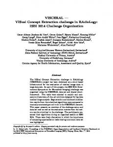
Figure 1: Polyhedral patterns on a knot. Top: three polyhedral patterns tiling a knot and optimized by our framework. All examples are combinatorially equivalent to a semi-regular pattern (3, 4, 6, 4). Bottom: each of the three solutions is induced by a choice of strip decomposition and corresponding affine symmetries. For each model, we show the strip decomposition (left) with the pattern in the plane colored by yellow and blue strips. We show the deformed pattern upon mapping to a cylinder, suggesting the feasible symmetries (right). The different colors encode different choices of symmetries. For instance, blue faces are symmetric with respect to the barycenter.
1 Abstract We study the design and optimization of polyhedral patterns, which are patterns of planar polygonal faces on freeform surfaces. Working with polyhedral patterns is desirable in architectural geometry and industrial design. However, the classical tiling patterns on the plane must take on various shapes in order to faithfully and feasibly approximate curved surfaces. We define and analyze the deformations these tiles must undertake to account for curvature, and discover the symmetries that remain invariant under such deformations. We propose a novel method to regularize polyhedral patterns while maintaining these symmetries into a plethora of aesthetic and feasible patterns. CR Categories: I.3.5 [Computer Graphics]: Computational Geometry and Object Modeling—Curve, surface, solid, and object representations Keywords: Architectural geometry, discrete differential geometry, polyhedral meshes, wallpaper tiling groups * Joint first authors. † Joint last authors.
Introduction
Architects and engineers are constantly pushing design boundaries by exploring new building shapes and modeling their appearances. Advances in architectural geometry have made it possible for many buildings to be shaped as freeform surfaces. To conform to construction constraints, such designs are often rationalized with meshes that have planar faces. These faces are then realized with common materials, such as wood (see Fig. 3) or glass. Symmetric tessellation patterns have often been used in art, architecture, and product design for their aesthetic merits. However, the use of these patterns was restricted to planar surfaces, such as windows, walls, or floors. Notable examples are Arabesques, stained-glass patterns, and mosaics [Abas et al. 1995; Lu and Steinhardt 2007]. Here, we seek to enrich architectural design by meshing freeform surfaces with tessellation patterns. Examples of those are in Figures 1 and 2. There are several key challenges in designing polyhedral patterns on curved freeform surfaces. Simply placing a given pattern on such a surface (e.g., by a parametrization) and optimizing for tile planarity without any regularization of tile shapes is bound to fail; planarity alone is severly underconstrained, and the process is apt to degenerate to solutions with zero-length edges or foldovers (see Figure 4). Moreover, an arbitrary choice of tile-shape regularization with commonly used measures, such as face or angle distortion, Laplacian smoothness, or edge-length preservation, might clash with the planarity constraint, resulting in over-constrained optimization. As a consequence, either the mesh is not planarized, or the desired regularity is not satisfied. (Figures 27 and 28 show examples.) Our solution to the problem is to study explicit constructions of polyhedral patterns that approximate surfaces with varying Gaussian curvature. We observe curvature-invariant regularities, namely different types of symmetries. We introduce a theoretical study of polyhedral patterns that explains our choice of regularizers, and which leads to an objective function that is neither over- nor under-constrained.
Figure 2: Cladding an interior space with a polyhedral pattern using wooden panels. The pattern transforms smoothly from positive to negative curvature regions.
Figure 3: A planar-hexagonal pavilion constructed with wooden panels [Krieg et al. 2014].
We show a set of results that demonstrate, for the first time, the computation of such patterns on surfaces that satisfy both planarity and regularity constraints. We focus on semi-regular patterns (see Figure 5), which are patterns comprising regular polygons. Our contributions are: • An analysis of surface approximation with polyhedral patterns by describing tile shape deformations, in order to accommodate for curvature. Consequently, we show how different strip decompositions result in a variety of patterns. • Affine symmetries that are curvature-invariant. We construct a family of regularizers encoding such symmetries: e.g., symmetries with respect to axes passing through vertices, edge midpoints, or face barycenters, and reflective symmetries with respect to planes. • A variety of polyhedral patterns that have not been demonstrated before.
2
Figure 4: Under- and over-constrained optimization illustrated on a quad mesh. The initial mesh is aligned with the parameter lines on a bilinear surface. The task is to planarize it. Left: Using mesh polyline smoothness as a regularizer results in an over-constrained problem, and acceptable planarity is not achieved (red color). Middle: Dropping the regularizer leads to an under-constrained problem, where the faces are perfectly planar, yet their appearance is chaotic and unaesthetic. Right: Using our regularizer, based on affine symmetries (with respect to edge midpoints), yields an aesthetically pleasing pattern with planar quads.
triangle meshes [Zimmer 2014; Li et al. 2014] or remeshing triangle meshes by parametrization and deformation [Vaxman and Ben-Chen 2015]. They are problematic in several aspects: the face shapes have to change considerably and even become concave in negatively curved areas. In addition, they have to transition smoothly between regions of negative and positive Gaussian curvature. We present a systematic way to regularize patterns between different curvature regions, including PH meshes as a special case. Special polyhedral patterns appear as by-products with circlepacking meshes [Schiftner et al. 2009] and special hexagonal support structures [Jiang et al. 2014]. However, these papers do not consider polyhedral patterns in a systematic way; aesthetics and regularity largely come from the structures the patterns have been derived from. Numerical optimization schemes for computing polyhedral surfaces include the alternating least-squares approach of [Poranne et al. 2013], the local-global projection method of [Bouaziz et al. 2012], the augmented Lagrangian algorithm of [Deng et al. 2015], and the guided projection method of [Tang et al. 2014]. Our computations are based on the latter approach, but are distinct from all the other aforementioned works by the novel use of local affine symmetries as regularizers, which are able to adapt to freeform geometry, and by the study of the curvature-dependent appearance of polyhedral patterns. Triangle meshes are trivial polyhedral meshes. Regularizing them for face and edge repetitivity is the aim of [Singh and Schaefer 2010] and [Huard et al. 2014]. These meshes also appear in triangle-based point folding structures [Zimmer et al. 2012]. Our symmetry-based regularizers can also be used for triangle mesh optimization.
Previous Work
Approximation with polyhedral meshes can be achieved with variational shape approximation [Cohen-Steiner et al. 2004]. However, the resulting unstructured mesh is built to satisfy required approximation accuracy and does not follow a prescribed pattern. Most previous works that focused on polyhedral mesh creation targeted planar quad (PQ) meshes. PQ meshes play a central role in discrete differential geometry [Sauer 1970; Bobenko and Suris 2008], and have attracted considerable interest in recent years, cf. [Liu et al. 2006; Liu et al. 2011; Zadravec et al. 2010], as their design is a core problem in architectural geometry. Planar hexagonal (PH) meshes have also been studied, but to a lesser extent. The simplest way to produce them is by taking the dual of
3
Geometry of Polyhedral Patterns
Creating polyhedral patterns first and foremost poses a theoretical challenge, since we do not possess the knowledge of how such patterns behave in different curvature regions. We have an understanding of planar-quad meshes as given by [Liu et al. 2006]. If the network of polylines that is characteristic of quad meshes follows conjugate directions, it is possible to achieve a mesh with smooth polylines. Unfortunately, this is not possible for any orientation of quads (see auxiliary material for a theoretical proof), and there has been no suggestion for what could be done in this case. An analysis is provided for feasible planar hexagonal tile shapes by [Li et al. 2014]. However, the description is particular for hexagons in principal directions, and the generalization to semi-regular patterns
(a) (34 , 6)
(b) (3, 4, 6, 4)
(c) (3, 6, 3, 6)
(d) (3, 12, 12)
(e) (4, 6, 12)
(f) (4, 8, 8)
(g) (34 , 6)∗
(h) (3, 4, 6, 4)∗
(i) (3, 6, 3, 6)∗
(j) (3, 12, 12)∗
(k) (4, 6, 12)∗
(l) (4, 8, 8)∗
Figure 5: Several patterns used in this paper: selected semi-regular patterns (top row; labels correspond to the valences of faces around a vertex) and their duals (bottom row). In our results, patterns (a) - (e) and (g) - (j) are derived from a hex-mesh, patterns (f) and (l) from a quad mesh, and pattern (k) from a triangle mesh.
is not obvious. In the following, we provide an analysis of feasible planar tile shapes in different curvature regions, for the general case of semi-regular tilings. In Section 6, we utilize the insights gained from this analysis, to establish a set of symmetries that remain invariant in each curvature region. We consequently use these symmetries as regularizers in our planarization algorithm. We base our geometric constructions on semi-regular patterns, which are tilings that can be derived in the plane by altering either of the three regular tilings: triangle, square, or hexagonal grids. Semi-regular tilings are characterized by several properties: First, the neighborhood of any vertex is perfectly similar to the neighborhood of any other. Second, such tiles constitute an orthogonal circle pattern: every tile has a circumcircle, and the dual segments between neighboring tile (circle) centers are orthogonal to the primal edge they share. This property is important when we discuss construction by lifting. We depict a range of semi-regular tilings that we employ in Figure 5. We denote tilings using vertex configuration shorthand by numbering the degree of faces around each vertex and using powers for multiples, e.g., a pure hexagonal pattern is 63 . We use the term “tile” to indicate a single face of the tiling, and either “tiling” or “pattern” to indicate the entire set. We often refer to the dual pattern as the pattern that is made by connecting dual face centers of adjacent primal tiles. Tilings that are not semi-regular exhibit several of these properties, and our consequent optimization results in interesting polyhedral patterns as well.
3.1
respective principal directions. The paraboloids are characterized as either elliptic (both curvatures are nonzero and have the same sign), hyperbolic (different nonzero signs), or cylindrical (one of the curvatures is zero). In case that κ1 = κ2 = 0, the osculating paraboloid is a plane, and we do not need to deal further with this trivial case. We consider discretizations of paraboloids by polyhedral patterns characterized by two properties: First, they are inscribed, which means the vertices of the pattern lie exactly on the paraboloid. Second, we have normal adherence. Assuming that the supporting plane to the inscribed tile encloses a well-defined small patch of the paraboloid, then there must be a point within the patch whose tangent plane is parallel to the supporting plane. Both properties can be generally relaxed, but it is cogent to study the pattern symmetry and regularity emerging from these most restrictive requirements. The analysis we give for tiling surfaces relies on lifting planar tiles onto paraboloids (see Figure 7). We then explore the tile shapes and topologies for which the lifting produces polyhedral patterns (preserving tile planarity). Given the paraboloid S2 , the vertices are � lifted (bijectively) by the function (x, y) → x, y, κ1 x2 + κ2 y 2 . The intersection of the supporting plane of the tile and the paraboloid is a conic, related to the Dupin indicatrix. The projection of the conic down to the plane is again a planar conic, endowed with required properties that we next detail. Moreover, the conic on the paraboloid is an affine image of the planar tile. See Figure 6 for an example. Lifting
Discretization of osculating paraboloids
We construct some explicit embeddings of polyhedral patterns on surfaces to study necessary deformations in tile shapes. Such deformations are the result of fitting planar patterns with given connectivities onto curved surfaces, while constraining each tile to remain planar. Our purpose is to derive the invariants of the required deformations, focusing on symmetries they fix. An understanding of such invariant symmetries serves as a guide to predicting the resulting pattern shapes expected within our optimization process. We locally approximate the original surface, S, to a second-order in a point, p ∈ S, with an osculating paraboloid, S2 . Assuming the z direction is parametrized to be in the direction of the normal, the formula defining the paraboloid is 2z = κ1 x2 + κ2 y 2 , where κ1 , κ2 are the principal curvatures, and the x and y axes are the
Figure 6: Lifting. Top: a circle lifted to an ellipse in a rotational paraboloid. Bottom: a hyperbola lifted to a hyperbolic paraboloid.
Polyhedral patterns on paraboloids are synonymous with consistent structures that are pivotal to our framework and that govern the deformations induced on tiles for consistent approximation of paraboloids. Assume that there are two neighboring tiles, i, j. Their centers are defined by looking at the centers of the conics on the paraboloid and projecting them down on the tiling Consistent tilings
pp ccccjjjjj ppiiiii ccciiiiii pp pjjjjjj
cccciiiiii
ppiiiii pp
ccccjjjjj pp pjjjjjj
cccciiiiii
pppiiiii
ccccjjjjj pp pjjjjjj
cccciiiiii
pppiiiii ccccjjjjj pjjjjjj pp
Figure 7: Lifting consistent tilings to paraboloids. Under the induced metric in the plane, the dual edge cij and the primal edge pij are conjugate. Both vectors are orthogonal in the rotational paraboloid case (left).
plane, producing ci , cj . The intersection points between them are the projected common vertices, pi , pj . We define the primal vector pij = pj − pi , and the dual vector cij similarly. Next, we consider the metric induced by the paraboloid: ha, bi := κ1 xa xb + κ2 ya yb . The lift of a planar tiling into a paraboloid is polyhedral if and only if: 1. Conjugacy: the primal and dual vectors are conjugate. i.e., they are orthogonal with respect to the metric (hpij , cij i = 0). 2. Bisection: The dual edge bisects the primal edge. We call a tiling that obeys both properties consistent. For completeness, we include a proof in the Appendix. Consistency brings about several key consequences: • If the paraboloid is a rotational-symmetric canonical paraboloid 2z = x2 + y 2 , then the duals and the primals are in fact also Euclidean orthogonal, as we demand from the original tilings. • If the paraboloid is cylindrical, then either the dual or the primal must be in the direction of the ruling (the direction of zero curvature). That means that the tiling has to comprise strips of faces that are parallel to the ruling direction. • If the paraboloid is hyperbolic, the dual and the primal can be identical (in asymptotic directions). We can potentially produce degenerate and concave tiles in this manner.
3.2
Figure 8: Deforming and lifting. Top: the paraboloid tilings. Bottom: top view of the tiling. Left to right: original (fit to the canonical paraboloid), anisotropic elliptic, cylindrical, and hyperbolic.
conic centers of the same strips are denoted as dual rulings, and the sequence of intersection edges bounding two strips are denoted as primal rulings. Next, fix all the tile (dual) centers and deform all (primal) vertices orthogonally to the ruling until they are on a parallel primal ruling. The actual position of the primal ruling is set as the ruling that is closest to the original primal vertices (see Figure 8 for a depiction of this process). Denote the original position of any primal vertex as pi , and the deformation vector for a cylindrical ˆ · uc,i = 0. pattern as uc,i . Then, y To unify our deformation setting and make it fit all types of paraboloids, we rephrase our construction for a cylindrical paraboloid in a local and continuous manner: we deform the primal edges of an initial tiling so that the (constant) dual and the primal are conjugate according to the induced metric, and the deformation is done according to the choice of strip decomposition, as in the cylindrical case. Suppose again that ˆ . We then need to find the the chosen direction of the dual strip is y deformation vector ui of vertex pi so that for each primal edge pij and dual edge cij we get hpj + uj − pi − ui , cij i = 0, according to the metric. Furthermore, we constrain ui = −uj for symmeˆ , it is straightforward to try. Since ui = −uj are orthogonal to y compute the actual deformation. Tiling elliptic and hyperbolic paraboloids
Fitting tiles to paraboloids Our deformation process is obviously invariant to scale. More accurately, it only pertains to the ratio of κ1 and κ2 and not their sizes. In addition, it is evident that tiles with more than 4 vertices must become non-convex in order to be inscribed in negatively curved regions; this is expected, since the conic in which the tile is inscribed is a hyperbola. Discussion
Given a planar tiling and a paraboloid of any shape, we next wish to deform the tiling on the plane, such that the lifting produces a polyhedral pattern. This should be done while keeping the shapes of the tiles as symmetric and as regular as possible and with minimal deformation. It is worth noting at this point that we use this construction for a theoretical, rather than a direct algorithmic, purpose; it is a general and arbitrary way to observe which symmetries are invariant within the deformation, and to motivate our use of such symmetries in pattern optimization for general surfaces, locally approximated as paraboloids. We initiate this analysis by considering the canonical rotational paraboloid Sr : 2z = x2 + y 2 . We take any semi-regular tiling on the plane. Without any deformation, the circular faces of the semi-regular tiling are then projected into ellipses in the paraboloid, which are planar by definition. We thus obtain a natural polyhedral pattern embedded in Sr for every semi-regular pattern. Without loss of generality, we assume that our cylinder is defined by Sc : z = κ2 y 2 , κ2 > 0. By the rule of conjugacy, the tiling must comprise strips that are parallel ˆ , to consistently tile the cylinder. In light of to the ruling direction, y this, and opting to deform the tiling as little and as symmetrically as possible, we do the following: decompose the tiling into strips of faces that are parallel to the rulings. The lines between dual Tiling cylindrical paraboloids
The deformation orthogonal to the chosen strip direction is the only one possible for tilings such as 63 . However, by constraining the consistency, and by conforming to the aesthetic request that the repeating faces of the same type must stay congruent, some tilings may in fact allow more degrees of freedom in deformation possibilities. This works only to our advantage. The deformations we defined maintain conjugacy and bisection for most semi-regular patterns, but not for some. For example, consider the (4, 6, 12) example in Figure 9: by fixing all the dual vertices, our deformation would violate bisection between some of the quads and the 12-sided faces. This is caused by the special structure of the (4, 6, 12) pattern, for which the dual centers of the hexes and the oblique quads cannot conform to straight rulings should they stay fixed. Our correction is simple: allow the centers of the hexes to deform as well, so that they line up with the (fixed) centers of the oblique quads. Violating consistency
Figure 11: Different strip decompositions increase the available types of polyhedral patterns. With the three strip decompositions shown in Figure 10, we obtain hexagon patterns approximating a cyclide with different appearances.
The practical meaning of choosing strips is to contrast a chosen strip direction with the principal directions of the paraboloid. Choosing a strip means choosing a dual axis for every consequent pair of faces, and forcing the primal vertices to move in directions that are orthogonal to the strip axis. In other words, we constrain a plane of symmetry that is orthogonal to the tile, and passes through its center. Deformations and symmetries
Figure 9: The dual centers of the (4, 6, 12) pattern do not correspond to possible rulings if fixed upon deformation. Allowing the hex (pink) centers to deform fixes this problem.
3.3
Strip decompositions
However, as we explain above, the principal directions may mandate (e.g., if they are rulings), that the surface forms lines of primal vertices along such rulings. At any rate, the tile must also be inscribed to a conic of the same nature. The canonical choice of strips is where the dual axis is aligned with the rulings (see Figure 10 left). However, other choices may produce interesting patterns due to the mismatch between the constrained symmetry and the rulings (see Figure 12), and they may potentially form invalid configurations. Such configurations arise when the strips are along the asymptotic directions of the surface, i.e., where the dual direction is self conjugate. Not all patterns can be decomposed to strips. For instance, the tri-hex pattern (3, 6, 3, 6) cannot be decomposed. Such patterns cannot therefore comply to the normal adherence and cannot be made consistent by deformation. However, as our algorithm requires consistency only for the theoretical analysis, we still utilize these patterns in practice, just without any guarantees. Figures 17 and 23 provide examples. General patterns
Our explicit construction provides a canonical way to approximate paraboloids, by relying on a single possible choice for defining strips. In the following, we explore other possible constructed solutions, by choosing different alignments, corresponding to decomposing the patterns into different strips. Essentially, strip decomposition is a combinatorial refinement of the original pattern. A feasible strip decomposition is a collection of disjoint dual strings (trees with 2-valence nodes; see Figure 10 for examples). Since a strip decomposition assigns primal vertices to dual vertices, it is actually a strip decomposition of the dual pattern as well. Regular quads, hexagons, (34 , 6), (3, 4, 6, 4), (4, 6, 12), (4, 8, 8) and their dual patterns have infinitely many strip decompositions. However, patterns such as (3, 6, 3, 6), (3, 12, 12) and their duals cannot be decomposed to strips by definition.
3.4
Figure 10: Different strip decompositions for regular hexagons. The three decompositions from the left correspond to the ones shown in Figure 11. In addition, the transformation corresponding to the decomposition second from the left is shown in Figure 12.
Figure 12: Transformation of the regular hexagon pattern from a rotational paraboloid (left) via a parabolic cylinder (middle) to a hyperbolic paraboloid (right) with the strip decomposition shown in Figure 10, second from left.
Decomposable patterns
Regularizers Motivated by Symmetries
Ideally, we would like to achieve the described symmetric and planar tile shapes for meshes initially tiled with semi-regular convex patterns. However, general meshes are not paraboloids, and they have a variety of strip decompositions and varying curvature regions. Not wanting to be particular for every pattern, we instead opt for the most general way to make any type of semi-regular pattern deform properly. Our point is to utilize what remains invariant under curvature-based tile deformations, rather then what deforms. There-
(a) (a) (a)
(b) (b) (b)
(c) (c) (c)
(d) (d) (d)
Figure 13: Framework overview: a) for an initial triangle, quad, or hex mesh, we can generate a pattern mesh using simple geometric rules. b) The initial pattern mesh might already be aesthetically pleasing, but the faces are typically not planar. c) A regularizer can be configured by specifying symmetries that should be preserved in the pattern. In this case, face symmetries are chosen. Corresponding vertex pairs are shown using the same number and the symmetry centers are shown in blue and red. d) Finally, the optimization generates a mesh with planar faces. The most interesting aspect of polyhedral patterns is that most of them have to transform so that they look different in regions of positive, zero, and negative Gaussian curvature (see insets).
fore, we identify invariant symmetries of tiles and then regularize the mesh in our planarization process to maintain them. The symmetries that we identify include reflection through axes and through planes as well as reflections through the centers of tiles or edges. It is straightforward to check that such symmetries are general enough to contain the deformations we describe here. The symmetries are described in greater detail in Section 6.
Symmetry optimization
4
We next describe the regularity-based planarity optimization framework that our work builds upon. The inputs are a reference surface, S, given as a triangle mesh, and an initial polygonal mesh with vertices, vi , that approximates the reference surface. The goal is to optimize the initial polygonal mesh, M = (V, E, F ), according to three terms: the planarity of the faces, the closeness to the reference surface, and the regularity of the mesh. We rely on existing methods (described in this section) to formulate planarity and closeness terms. The regularity terms are our contribution.
Overview and User Interaction
Our framework comprises four stages, shown in Figure 13. Initial meshes are generated using triangular-, quad-, or hex-based remeshing techniques in a separate program, according to the desired pattern (see Figure 5 for a description). Many patterns are initialized using the hex-based remeshing approach proposed by Vaxman and Ben-Chen [2015] with their planarity optimization omitted. We therefore have two input meshes in our system: A finely-tessellated triangle mesh to define the reference surface and a coarser (non-planar) remeshed triangle, quad, or hex mesh. Pre-processing
The user can transform the initial coarse mesh into a pattern mesh by selecting from a list of pre-defined patterns. The transformation is implemented using a sequence of geometric rules, e.g., subdivision rules. The implementation of such rules is fairly straightforward and follows the framework proposed by Akleman et al. [2005].
Our algorithm optimizes the pattern for planarity and aesthetics (using the regularizer configured in the previous step) through non-linear optimization. The details for the optimization framework are presented in Section 5, and those for the symmetry regularizers are given in Section 6.
5
Optimization Framework
Variables We denote the vertex coordinates of M as vi , i ∈ V , and the unit face normals as nk , k ∈ F . Vertices are not constrained to lie on the reference surface, S, exactly. The closest point on S for a vertex vi is vi∗ with corresponding normal n∗i (see Fig. 14).
Pattern generation
The user can then specify a desired strip decomposition and configure the regularizer by assigning symmetries. We offer axial symmetries with respect to an axis passing through a vertex, an edge midpoint, or a face barycenter. We also offer reflective symmetries with respect to a plane, e.g., a plane passing through an edge. The user specifies the symmetry assignment for one or more elements, and the system propagates the assignment over the whole mesh according to the strip decomposition. To guide the user in his/her selection, we provide a list of suggested symmetries. The suggestions are generated by mapping each strip decomposition of each pattern to a cylinder and then observing what symmetries are feasible (see Sec. 3). Symmetry configuration
n nkkkkkk n
n∗i∗i∗i∗i∗i∗i n n
v viiiiii v v v v viiiiii
v vi∗ii∗∗ii∗∗i∗ v
v vjjjjjj v v
Figure 14: Notation: faces (left), closest point projection (right)
Problem formulation
The objective function we minimize is
E(vi ) = λ1 Eplan + λ2 Eclose +
X
j µj Ereg .
(1)
j
Following the reasoning of [Tang et al. 2014], we set up a system with energies that are at most quartic, which entails soft constraints that are at most quadratic, since this formulation is easy to optimize using a standard regularized Gauss-Newton algorithm.
The planarity constraint is necessary for all nontriangular faces. We adapt the formulation of [Tang et al. 2014] and express Eplan as Planarity
Eplan =
X
X
((vi −vj )·nk )2 +
❶
❶
X (nk ·nk −1)2 , (2)
k∈F (i,j)∈E(fk )
⓿
⓿
The closeness constraint of a vertex, vi , to a reference surface is modeled by requiring vi to move only on the tangent plane associated with its closest point, vi∗ , on the reference surface, S: X Eclose = ((vi − vi∗ ) · n∗i )2 . (3)
❷
⓿
❶
❹
⓿
❶
❺ ⓿
⓿
❶
⓿
❺
❶
⓿
❹ ❶
❶
❷
❸
k
which is zero if all face edges are orthogonal to a unit length normal.
❸
Figure 16: Left to right: symmetry with respect to a vertex, an edge midpoint, a face barycenter, and an edge.
Closeness
vi ∈V
n∗i
As shown in Figure 14, is the normal of the tangent plane at vi∗ , and it is kept constant in every iteration. Alternatively, for coarse and inconsistent tilings, we may use closeness of face barycenters instead to relax this constraint (see Figures 18 and 29, left).
An affine reflection in an axis, Ak , requires the additional prescription of a reference plane, Tk (not parallel to Ak ; see Fig. 15, left). Then, a pair of vertices vi and vj is symmetric with respect to Ak if the midpoint between vi and vj lies on Ak and the vector vi − vj is parallel to Tk . Let Ak be defined by a direction vector ak and a point ck , and let n∗k be a normal vector of Tk . Then, 1 the axial symmetry regularizer Ereg is encoded as follows: X ((vi + vj )/2 − (ck + λkl ak ))2 + ((vi − vj ) · n∗k )2 (5) Axial symmetries
(i,j,k)
We add a term in each iteration that dampens the optimization for stability by closeness to the previous iteration: Previous iteration
Eprev = β
X m X m 2 vi − vim−1 2 + β ni − nm−1 , (4) i vi ∈V
ni ∈F
where m denotes the number of an iteration and vim is the value of vi at iteration m. We use β = 10−6 in all our examples.
6
Regularization with Affine Symmetries
We next define the invariant symmetries of deforming patterns (see Section 3) and how we utilize them in practice to regularize patterns undergoing deformations through the planarization process. Generally speaking, there are several ways to represent feasible regularities, such as enforcing specific angles, polyline smoothness of selected sequences of non-adjacent vertices, ratios of edge lengths, and more. We choose to use local affine symmetries as described in the following, because they are simple, sparse, local and linear (e.g., compared with angle-based formulations), and this is important for computational efficiency. We describe the practical implementation of various symmetry regularizers and adapt them to the discrete surface by two approaches: affine symmetries in space and in a tangential projection. Each approach has different merits and shortcomings.
6.1
Affine symmetries
Affine symmetries can be defined with respect to either an axis or a plane. We can distinguish four different generators of symmetries: vertices, faces, edge midpoints, and edges. Vertices, faces, and edge midpoints generate symmetries with respect to an axis and edges generate symmetries with respect to a plane. Ak vj
vi n∗k Tk
ak ck
vj vi rk ¯k n
The triplets (i, j, k) are chosen according to the user-assigned symmetries. That is, vi and vj are selected to have affine symmetry with respect to Ak . Furthermore, ak and λkl are considered as additional variables in our optimization. The axis point ck is a vertex, an edge midpoint, or a face barycenter, and thus it is a linear combination of vertex coordinates. The n∗k variables can be either considered as additional variables, or approximated at the beginning of each iteration as the normal of S at the closest point to ck . We do the latter. Symmetry is applied to local neighborhoods as illustrated in Fig. 16. Note that the symmetry of a planar face with respect to its barycenter does not require an axis. n∗k = ak models a Euclidean reflection in Ak and is therefore suitable to enforce Euclidean symmetries. Fig. 15 (right) presents an affine reflection with respect to a plane, Pk (through point bk and with ¯ k ), in the direction rk . Plane-reflective symmetry normal vector n of vi and vj requires their midpoint to be located on Pk , and the vector vi − vj to be parallel to rk . We encode this requirement in 2 the regularizer, Ereg , as follows: X ¯ k )2 + ((vi − vj ) − λkl rk )2 . (6) (((vi + vj )/2 − bk ) · n Plane-reflective symmetries
(i,j,k)
We use rk for each reflection plane and the scale variable λkl as additional variables. The plane Pk is commonly the bisection plane of two adjacent faces in a polyhedral mesh, and so bk can be the midpoint of the common edge of two adjacent faces. The normal, ¯ k , is then pre-estimated in each iteration. With rk = n ¯ k , we obtain n a Euclidean reflection. In Fig. 16, as exemplified on a quad mesh, the three leftmost images show point symmetries in 2D, equivalent to 3D axial symmetries. The blue dot represents the symmetry center. Each pair of symmetric points is labelled the same (orange dots). Their symmetry centers are located at a vertex, an edge midpoint or a face barycenter, and their symmetries are denoted accordingly. The rightmost edge symmetry is equivalent to a 3D planar symmetry. Symmetry centers
bk Pk
Figure 15: Affine reflection in an axis (left) and in a plane (right)
6.2
Symmetry in a tangential projection
A relaxed version of affine axial symmetry is symmetry in a projection parallel to a certain direction (the image plane of the projection does not matter). To achieve it, we simply discard the second part of
Figure 17: Semi-regular patterns on a Dupin cyclide. Left: A (3, 4, 6, 4) pattern using face symmetries. Middle: A (3, 6, 3, 6)∗ pattern using symmetries with respect to an edge. Right: A (4, 8, 8) pattern using face symmetries.
Equation 5. We use the normal at the closest point, c∗k , to ck as the projection direction, and thus enforce a symmetry that is relative to 3 the tangent plane of S at c∗k . This yields the regularizer Ereg : X ((vi + vj )/2 − (ck + λkl ak ))2 . (7) (i,j,k)
By approximating ak with n∗k , this expression can be simplified to the following equivalent formulation: X (((vi + vj )/2 − ck ) · tkl )2 . (8) (i,j,k,l)
In addition, we need to sum over two orthogonal directions, tk1 and tk2 . Both directions are orthogonal to n∗k , and they are estimated at the beginning of each iteration.
6.3
Avoiding self-intersection
The proposed symmetry regularizers cannot prevent selfintersections within the pattern. To counter that, we introduce an 4 additional regularizer, Ereg , assuming that a line segment connecting the face barycenter to a vertex is within the corresponding face: X 2 2 ((ˆ vki − ck ) × (ˆ vki+1 − ck ) · nk − νki ) . (9)
γ α
β
α = 56.3◦ β = 27.2◦ γ = 96.5◦
Figure 18: Triangle meshes constructed by a single type of triangle for the (4, 8, 8)∗ pattern (left) and the (4, 6, 12)∗ pattern (right) using symmetries with respect to an edge.
7
Results
We present several results and discuss parameters, planarity, running time, failure cases, and comparison to related work.
k∈F 0≤i