Portable waveguide display system with a large field of view by integrating freeform elements and volume holograms Jian Han,1 Juan Liu,1,* Xincheng Yao,2 and Yongtian Wang1 1
Beijing Engineering Research Center for Mixed Reality and Advanced Display, School of Optoelectronics, Beijing Institute of Technology, Beijing, 100081, China 2 Department of Bioengineering, University of Illinois at Chicago, Chicago, Illinois 60607, USA *
[email protected]
Abstract: A compact waveguide display system integrating freeform elements and volume holograms is presented here for the first time. The use of freeform elements can broaden the field of view, which limits the applications of a holographic waveguide. An optimized system can achieve a diagonal field of view of 45° when the thickness of the waveguide planar is 3mm. Freeform-elements in-coupler and the volume holograms outcoupler were designed in detail in our study, and the influence of grating configurations on diffraction efficiency was analyzed thoroughly. The offaxis aberrations were well compensated by the in-coupler and the diffraction efficiency of the optimized waveguide display system could reach 87.57%. With integrated design, stability and reliability of this monochromatic display system were achieved and the alignment of the system was easily controlled by the record of the volume holograms, which makes mass production possible. © 2015 Optical Society of America OCIS codes: (090.2870) Holographic display; (090.2890) Holographic optical elements; (090.7330) Volume gratings; (220.2740) Geometric optical design; (220.4830) Systems design.
References and links 1. 2. 3. 4. 5. 6. 7. 8. 9. 10. 11. 12. 13.
J. Carmigniani, B. Furht, M. Anisetti, P. Ceravolo, E. Damiani, and M. Ivkovic, “Augmented reality technologies, systems and applications,” Multimedia Tools Appl. 51(1), 341–377 (2011). J. P. Rolland and K. Thompson, “See-Through Head Worn Displays for Mobile Augmented Reality,” Commun. China Comp. Fed. 7(8), 28–37 (2011). H. Hoshi, N. Taniguchi, H. Morishima, T. Akiyama, S. Yamazaki, and A. Okuyama, “Off-axial HMD optical system consisting of aspherical surfaces without rotational symmetry,” Proc. SPIE 2653, 234–242 (1996). D. Cheng, Y. Wang, H. Hua, and M. M. Talha, “Design of an optical see-through head-mounted display with a low f-number and large field of view using a freeform prism,” Appl. Opt. 48(14), 2655–2668 (2009). D. Cheng, Q. Wang, Y. Wang, and G. Jin, “Lightweight spatial-multiplexed dual focal-plane head-mounted display using two freeform prisms,” Chin. Opt. Lett. 11(3), 31201–31204 (2013). H. Hua, A. Girardot, C. Gao, and J. P. Rolland, “Engineering of head-mounted projective displays,” Appl. Opt. 39(22), 3814–3824 (2000). H. Hua, X. Hu, and C. Gao, “A high-resolution optical see-through head-mounted display with eyetracking capability,” Opt. Express 21(25), 30993–30998 (2013). R. Martins, V. Shaoulov, Y. Ha, and J. P. Rolland, “A mobile head-worn projection display,” Opt. Express 15(22), 14530–14538 (2007). A. J. Wright, B. A. Patterson, S. P. Poland, J. M. Girkin, G. M. Gibson, and M. J. Padgett, “Dynamic closed-loop system for focus tracking using a spatial light modulator and a deformable membrane mirror,” Opt. Express 14(1), 222–228 (2006). S. C. McQuaide, E. J. Seibel, J. P. Kelly, B. T. Schowengerdt, and T. A. Furness III, “A retinal scanning display system that produces multiple focal planes with a deformable membrane mirror,” Displays 24(2), 65–72 (2003). E. Fernandez and P. Artal, “Membrane deformable mirror for adaptive optics: performance limits in visual optics,” Opt. Express 11(9), 1056–1069 (2003). M. Beuret, P. Twardowski, and J. Fontaine, “Design of an off-axis see-through display based on a dynamic phase correction approach,” Opt. Express 19(20), 19688–19701 (2011). H. H. Tobben, B. Lorenz, and S. Schmerwitz, “Design of a pathway display for a retinal scanning HMD,” Proc. SPIE 5802, 102–111 (2005).
#229277 - $15.00 USD © 2015 OSA
Received 12 Dec 2014; revised 29 Jan 2015; accepted 29 Jan 2015; published 4 Feb 2015 9 Feb 2015 | Vol. 23, No. 3 | DOI:10.1364/OE.23.003534 | OPTICS EXPRESS 3534
14. M. M. Bayer, “Retinal scanning display: a novel HMD approach for army aviation,” Proc. SPIE 4711, 202 (2002). 15. B. T. Schowengerdt, R. S. Johnston, C. D. Melville, and E. J. Seibel, “3D Displays using Scanning Laser Projection,” SID Symposium Digest of Technical Papers, 43: 640–643 (2012). 16. X. Yang, Z. Wang, and R. Fu, “Hybrid diffractive-refractive 67-diagonal field of view optical see-through headmounted display,” Optik-International Journal for Light and Electron Optics 116(7), 351–355 (2005). 17. J. A. Cox, T. A. Fritz, and T. R. Werner, “Application and demonstration of diffractive optics for head-mounted displays,” Proc. SPIE 2218, 32 (1994). 18. B. Kress and T. Starner, “A review of head-mounted displays (HMD) technologies and applications for consumer electronics,” Proc. SPIE 8720, 87200A (2013). 19. H. Li, X. Zhang, G. Shi, H. Qu, Y. Wu, and J. Zhang, “Review and analysis of avionic helmet-mounted displays,” Opt. Eng. 52(11), 110901 (2013). 20. R. Shechter, S. Reinhorn, Y. Amitai, and A. A. Friesem, “Planar holographic elements with uniform diffraction efficiency,” Appl. Surf. Sci. 106, 369–373 (1996). 21. R. Shechter, Y. Amitai, and A. A. Friesem, “Compact beam expander with linear gratings,” Appl. Opt. 41(7), 1236–1240 (2002). 22. J. P. Sharpe, T. Post, S. Khatri, and G. Halpin, “Fabrication and characterization of optical waveguides and grating couplers,” Eur. J. Phys. 34(5), 1317–1326 (2013). 23. J. Piao, G. Li, M. Piao, and N. Kim, “Full Color Holographic Optical Element Fabrication for Waveguide-type Head Mounted Display Using Photopolymer,” J. Opt. Soc. Korea 17(3), 242–248 (2013). 24. I. Gurwich, V. Weiss, L. Eisen, M. Meyklyar, and A. A. Friesem, “Design and experiments of planar optical light guides for virtual image displays,” Proc. SPIE 5182, 212–221 (2004). 25. http://www.lumus-optical.com/ 26. http://www.epson.com/cgi-bin/Store/jsp/Moverio/Home.do?BV_UseBVCookie=yes 27. http://www.google.com/glass/start/ 28. K. Sarayeddine and K. Mirza, “Key challenges to affordable see-through wearable displays: the missing link for mobile AR mass deployment,” Proc. SPIE 8720, 87200D (2013). 29. http://optinvent.com/HUD-HMD-benchmark 30. http://www.lumus-optical.com/index.php?option=com_content&task=view&id=10&Itemid=16 31. Y. Amitai, “Extremely Compact High-Performance HMDs Based on Substrate-Guided Optical Element,” SID Symposium Digest of Technical Papers, 35: 310–313 (2004). 32. P. Äyräs, and P. Saarikko, “Near-to-eye display based on retinal scanning and a diffractive exit-pupil expander”, Proc. SPIE 7723, 77230V (2010). 33. T. Levola and P. Laakkonen, “Replicated slanted gratings with a high refractive index material for in and outcoupling of light,” Opt. Express 15(5), 2067–2074 (2007). 34. T. Levola, “Novel Diffractive Optical Components for Near to Eye Displays,” SID Symposium Digest of Technical Papers, 37: 64–67 (2006). 35. I. Kasai, Y. Tanijiri, E. Takeshi, and U. Hiroaki, “A practical see-through head mounted display using a holographic optical element,” Opt. Rev. 8(4), 241–244 (2001). 36. H. Mukawa, K. Akutsu, I. Matsumura, S. Nakano, T. Yoshida, M. Kuwahara, K. Aiki, and M. Ogawa, “A Full Color Eyewear Display using Holographic Planar Waveguides,” SID Symposium Digest of Technical Papers, 39: 89–92 (2008). 37. I. K. Wilmington and M. S. Valera, “Waveguide‐Based Display Technology”, SID Symposium Digest of Technical Papers, 44: 278–280 (2013). 38. A. A. Cameron, “Optical waveguide technology and its application in head-mounted displays,” Proc. SPIE 383, 83830E (2012). 39. http://www.baesystems.com. 40. L. Eisen, M. Meyklyar, M. Golub, A. A. Friesem, I. Gurwich, and V. Weiss, “Planar configuration for image projection,” Appl. Opt. 45(17), 4005–4011 (2006). 41. R. Shi, J. Liu, H. Zhao, Z. Wu, Y. Liu, Y. Hu, Y. Chen, J. Xie, and Y. Wang, “Chromatic dispersion correction in planar waveguide using one-layer volume holograms based on three-step exposure,” Appl. Opt. 51(20), 4703– 4708 (2012). 42. Z. Wu, J. Liu, R. Shi, and Y. Wang, “The recording method of planar holographic grating with variable diffraction efficiency by phase modulations,” Opt. Commun. 298–299, 41–45 (2013). 43. H. Kogelnik, “Coupled wave theory for thick hologram gratings,” Bell Syst. Tech. J. 48(9), 2909–2947 (1969). 44. A. M. Weber, W. K. Smothers, T. J. Trout, and D. J. Mickish, “Hologram recording in du Pont's new photopolymer materials,” (1990), pp. 30–39. 45. Y. Yamagishi, T. Ishizuka, T. Yagishita, K. Ikegami, and H. Okuyama, “Holographic Recording Material Containing Poly-N-vinyl carbazole,” (1986), pp. 14–19.
1. Introduction With the prosperity of augmented reality (AR) technology in navigation, education, entertainment, military operations, and biomedical applications [1,2], portable see-though displays are playing indispensable roles. There are many approaches such as using prisms [3– 5], projection systems [6–8], deformable membrane mirrors [9–11], retinal scanning [12–15],
#229277 - $15.00 USD © 2015 OSA
Received 12 Dec 2014; revised 29 Jan 2015; accepted 29 Jan 2015; published 4 Feb 2015 9 Feb 2015 | Vol. 23, No. 3 | DOI:10.1364/OE.23.003534 | OPTICS EXPRESS 3535
hybrid diffractive-refractive lenses [16,17], and optical waveguides [18–24] to realize a seethrough display and the most promising approach is an optical waveguide. An optical waveguide display, involving geometrical waveguides and diffraction waveguides, is an ultra-thin off-axis see-through display system, and it is appropriate for integration with a light-weight wearable device. The advantages of a waveguide display system (WGDS) have attracted the interest of many researchers and have become a topic of great interest. Some corporations, such as Lumus [25], Epson [26], Google [27], and Optinvent [28], have released products based on geometrical waveguides. However, the field of view (FOV) of Google Glass is only 14° [29], and the largest product from Lumus; i.e., Lumus PD-18, is 32° [30]. Amitai [31] described a light-guide optical element with cascaded partially reflecting surfaces functioning as an out-coupler. In order to avoid a ghost image, designing a complex layer and sophisticated coating craft was required. For a waveguide display based on diffraction theory, Nokia [32–34], Konica Minolta [35], Sony [36] and BAE Systems [37–39] corporations have used diffractive optical elements (DOEs) or holographic optical elements (HOEs) to develop their waveguide display systems. Though DOEs can achieved high diffraction efficiency, the feature sizes of the DOEs and the FOV of the display are a trade-off (Nokia). Slanted gratings can provide a FOV of 25° with a refractive index of 1.71 for the substrate. The other three companies employed volume holograms (VHs) in the display systems, where the feature sizes of the VHs could reach nanometers by holographic recording and the FOV could be enlarged. For instance, BAE Systems can even achieve a FOV of 50° (Q-Sight) with a diffraction efficiency < 1% and reduced contrast due to scattering and stray-light [1] because of the multilayer pupil expanders (BAE Systems) or double VH coupler (Sony). Eisen et al. [40] produced a system with three holographic gratings for in-coupling light into the waveguide and expanded the eye box along orthogonal directions. Shi et al. [41] proposed a simple method to eliminate the chromatic aberration of a certain holographic WGDS. Wu et al. [42] further improved the diffraction efficiency of this system. However, most of the cases above employed extra optical relay systems to collimate the image sources, which significantly increased the weight and the size of the WGDS. In this paper, we describe the design of a portable WGDS that employed the integration of volume holograms and freeform elements. It is a monochromatic display, where freeform element works as both an in-coupler to directly couple the image source into the waveguide and a collimator to convert the spherical waves into plane waves, and the volume hologram served as an out-coupler. Regardless of the loss of energy during optical propagation and the loss of efficiency during recording of the material, a FOV of 45° in diagonal and a diffraction efficiency of 21.71% were reached. After optimization, this efficiency can theoretically be raised to 87.57%. 2. Description of the optical system 2.1 General description The WGDS presented in this paper consisted of three parts, as is shown in Fig. 1, which are freeform elements (FFEs) in-coupler used to collimate and amplify the image from the microdisplay, an optical waveguide to guide light in the off-axis direction, and volume holograms that provided two optical paths to diffract the virtual image from the micro-display as well as to transmit external light. The light from the image source was collimated and coupled into the waveguide by freeform elements, and subsequently was transmitted to the other end of the waveguide according to the total internal reflection (TIR).Finally, they were coupled out by reflection VHs. Thus, the virtual image superimposed on the real scene could be observed in the position of the eye box.
#229277 - $15.00 USD © 2015 OSA
Received 12 Dec 2014; revised 29 Jan 2015; accepted 29 Jan 2015; published 4 Feb 2015 9 Feb 2015 | Vol. 23, No. 3 | DOI:10.1364/OE.23.003534 | OPTICS EXPRESS 3536
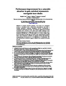
Fig. 1. (a) Sketch of integrated optical waveguide. (b) Parameters of the optical waveguide
Figure 1 shows a schematic diagram of the entire system, where n0 is the index of the incoupler, waveguide planar and holographic film, D is the thickness, ER is the eye relief, θ i is the propagation angle in the waveguide. The eye’s position in the system, as well as the exit pupil’s position of the in-coupler, was determined by the parameters n0 , D , ER and θ i . The in-coupler was carefully designed to match the position of the exit pupil with the eye perfectly, which is discussed in Section 2.2. The variables n0 and θ i , along with diffraction efficiency and angular bandwidth jointly determined the configuration of the out-coupler, which is analyzed in Section 2.3. Since the freeform elements compensated for aberrations and generated a clear image at a certain place, and the VHs here acted as selective reflectors, and the parts mentioned above serve the WGDS individually. Therefore, they can be designed independently. 2.2 Specifications of an in-coupler As mentioned above, the freeform elements compensated for aberrations and generated a clear image at the eye position. It is critically important to fix the exit pupil position, which is exactly the eye position for observation of the whole system. As the only aberration corrector of the display system, the in-coupler must be capable of coupling light into the thin waveguide as well as forming a clear virtual image for observation. In this case, the in-coupler needed two pupil positions to couple light into and out of the waveguide. As is shown in Fig. 1(b), the coupled-in pupil ( Si ) placed in the connections of the waveguide and the in-coupler ensured in-coupling efficiency, and the coupled-out pupil ( So ) placed in the eye position of the display system ensured the correctness of observation. The position of the eye pupil So satisfied the following equation: EP =
#229277 - $15.00 USD © 2015 OSA
ER 2mD , +D+ n0 cos(θ i )
(1)
Received 12 Dec 2014; revised 29 Jan 2015; accepted 29 Jan 2015; published 4 Feb 2015 9 Feb 2015 | Vol. 23, No. 3 | DOI:10.1364/OE.23.003534 | OPTICS EXPRESS 3537
where m is the number of TIR. With n0 =1.52 at a wavelength of 532 nm , the critical angle of TIR was 42° . An in-coupler with ER = 20 mm and FOV of 18° in the Y-direction was designed to make the central propagating angle θ i 52° . Taking D = 3 mm and four successive TIR into consideration, EP was calculated to be about 64mm. The in-coupler integrated with the waveguide was composed of two surfaces, as schematically presented in Fig. 2(a). The light emitted by the micro-display was refracted by the transmission surface ( S1 ) situated close to the micro-display, and was subsequently reflected by ( S 2 ), and, after that, the image could be magnified and simultaneously collimated.
Fig. 2. (a) Schematic view of the in-coupler. The subfigure in the lower-left dashed frame illustrates the position of the XY polynomial surface S1, the aspherical surface S2 and the coupled-in pupil Si. Colored lines refer to light emitted from micro-display and modified by the in-coupler. (b) Ray-tracing diagram of the WGDS. (c) Schematic top view of the expanded optical path of the in-coupler.
According to the above layout, we described its parameters and optimized its structure in a commercial software; i.e., CODEV, for optical design of the in-coupler. The propagating light should satisfy the following conditions: (1) meet the condition of TIR; and (2) entirely couple
#229277 - $15.00 USD © 2015 OSA
Received 12 Dec 2014; revised 29 Jan 2015; accepted 29 Jan 2015; published 4 Feb 2015 9 Feb 2015 | Vol. 23, No. 3 | DOI:10.1364/OE.23.003534 | OPTICS EXPRESS 3538
in at aperture Si and couple out to the eye position of So . In detail, the marginal FOV must be greater than the critical angle of the TIR to guarantee that the image wave is trapped inside the waveguide; Point P1 should be situated on the right side of the marginal light L2 and on the upper side of the S1 concurrently to overcome the crosstalk of the transmitted light from S1 and the reflected light from S 2 .The relationships described above can be expressed as: θ i1 > θ i 0 > θi 2 > θTIR y − y > 0 p1′ p1 y p1 − y p1′′ > 0 z p1 − z p1′ > 0 z p1′′ − z p2 > 0
(2)
where θ i 0 , θ i1 and θ i 2 are the propagating angles of the central and marginal FOVs in the waveguide, and θTIR is the critical angle of TIR. The variables y p1 , y p1 ' and y p1 '' denote the Y coordinates of points p1 , p1′ and p1′′ , respectively, as marked in Fig. 2(a) under a global coordinate system, where N OWG is exactly the direction of Z axis. z p1 , z p ′ , z p ′′ and z p2 are 1
1
the Z coordinates of the marked points p1 , p1′ , p1′′ and p2 in Fig. 2(a). In this design, θi 0 is 52° , which brings about 43° of θi 2 and 61° of θ i1 . Furthermore, a 0.61 in micro-display with 1024 × 768 pixels was used as the image source. With these constraints, optimizations were run to find the best solution. Finally, the asphere of S1 and the XY-Polynomial of S 2 were adopted. The distance between them was 10.5 mm and the width was 7 mm . The FOV was 24°× 18° ( X × Y ), and the exit pupil of the in-coupler was 4 mm . The Ray-tracing diagram of the whole system and the top view of the expanded optical path of the in-coupler are shown in Fig. 2(b) and Fig. 2(c). The performance of this in-coupler is analyzed below.
Fig. 3. MTF curves of in-coupler with some evaluated FOVs. Where the solid lines and dashed lines represent the tangential and radial MTFs of certain FOVs separately. The coordinates with ‘MAX’ mean the pupil ratio of the sampled light, and coordinates with ‘DEG’ mean the angle.
#229277 - $15.00 USD © 2015 OSA
Received 12 Dec 2014; revised 29 Jan 2015; accepted 29 Jan 2015; published 4 Feb 2015 9 Feb 2015 | Vol. 23, No. 3 | DOI:10.1364/OE.23.003534 | OPTICS EXPRESS 3539
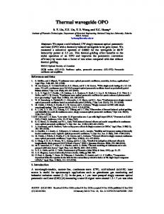
In Fig. 3, the modulation transfer function (MTF) of the central and marginal FOVs are plotted. These were evaluated with a full pupil and all of them were above 0.3 at 30 lp/mm, which was sufficient for the visual system. Numerical simulations were carried out to provide validation of the system, and the results are shown in Fig. 4. We set the resolution chart for the ideal image, as shown in Fig. 4(a), and the final received image by the human eye is shown in Fig. 4(b). It is clearly seen that there exists distortion at the edge of the received image. To analyze the distortion, we further investigated the grid of distortion, and the result is shown in Fig. 4(c).
Fig. 4. Simulation results (a) Ideal image of the resolution chart. The inserted box highlights the partial amplification of the central spline. (b) Received image by the human eye. (c) Distortion grid of the in-coupler. (Blue grid shows the distortion of the paraxial FOV, and red grid gives the real distortion.
The results showed that a clear image can be observed at the position of the eye through this in-coupler, and there was less than 4% distortion at the bottom corners of the image, which was slightly observed and easily canceled out by pre-compensating the input images electronically, if necessary. Considering practical performance, a tolerance analysis is run after in-coupler design. Monte Carlo trials are carried on for 2000 times and tolerance curves are plotted at the characteristic frequency of 30 cycles/mm with MTF vs. cumulative probability. Figure 5(a) and (b) show the tolerance in central and marginal FOV of the incoupler respectively. From Fig. 5 we can read that except for the very marginal FOV, the freeform in-coupler can be realized with MTF declining less than 0.2. It is in high probability to produce such freeform in-coupler as designed in good performance.
#229277 - $15.00 USD © 2015 OSA
Received 12 Dec 2014; revised 29 Jan 2015; accepted 29 Jan 2015; published 4 Feb 2015 9 Feb 2015 | Vol. 23, No. 3 | DOI:10.1364/OE.23.003534 | OPTICS EXPRESS 3540
Fig. 5. Illustration of system in tolerance with (a) central FOV and (b) marginal FOV of freeform in-coupler
2.3 Principles of the out-coupler As mentioned above, the multiplexing reflection volume holograms were used to guarantee the FOV provided by the in-coupler. Based on the coupled wave theory, the reflection volume hologram is relatively more sensitive to wavelength and less sensitive to incident angle compared with the transmission counterpart, which is necessary to ensure a smaller spectral bandwidth and a larger FOV for a single VH. Besides, for a certain wavelength, a very high diffraction efficiency but a small FOV was achieved under the Bragg condition due to the angular sensitivity of the VHs in the holographic waveguide display system, which definitely limited the entire FOV in the Y-direction. In order to enlarge the FOV, multiplexing reflection VHs were employed in our scheme. The triple-multiplexing VHs as an out-coupler were used to guarantee the 18° FOV along the Y-direction in the waveguide. This multiplexing VHs was kind of one complex hologram in one layer. The VHs were exposed in the holographic media with the same refractive index as the waveguide placed at the top of the waveguide planar. The light propagated through the waveguide matching the principle of total internal reflection, and finally was extracted to the eye via the out-coupler, as shown in Fig. 6 below.
#229277 - $15.00 USD © 2015 OSA
Received 12 Dec 2014; revised 29 Jan 2015; accepted 29 Jan 2015; published 4 Feb 2015 9 Feb 2015 | Vol. 23, No. 3 | DOI:10.1364/OE.23.003534 | OPTICS EXPRESS 3541
Fig. 6. (a) Diffractive optical path of the sampled light. (b) Recording diagram of the reflection VH (c) Relationship of the angular bandwidth of each sampled light and the FOV in the substrate. Blue, green and purple triangles stand for the anguler bandwidths of 6°, 0° and −6°, respectively.
VHs possess high diffraction efficiency but large angular sensitivity, which limits the FOV in the Y-direction. By triple-multiplexing the VHs in the same plane with the grating vectors parallel to each other, the out-coupler could achieve a large FOV. In that case, the VHs functioned as a liner grating with high diffraction efficiency. In order to facilitate the design, Lmc was named for the primary light of the central FOV, with Lrc and Llc named for the primary lights of 6° and −6° FOV, respectively, as shown in Fig. 6(a). With these sampled lights, a FOV of 18° could be achieved by recording triple-multiplexing VHs, whose characteristic angles satisfied the Bragg condition perfectly, and angular bandwidths that were larger than ± 3°. For specification, the triple-multiplexing VHs was decomposed into three parallel dielectric gratings working correspondingly to the three characterized incident light. These characterized dielectric gratings and their lossless diffraction efficiency are given by [43]: 2Λ i n0 sin θ i = λ ,
#229277 - $15.00 USD © 2015 OSA
(3)
Received 12 Dec 2014; revised 29 Jan 2015; accepted 29 Jan 2015; published 4 Feb 2015 9 Feb 2015 | Vol. 23, No. 3 | DOI:10.1364/OE.23.003534 | OPTICS EXPRESS 3542
ηi =
yi 2 ( ch 2 X i − 1)
yi 2 ( ch2 X i + 1) − 2 xi 2
,
(4)
with Xi = yi =
xi =
yi 2 − xi 2 ,
πΔnd λ α i βi
,
Δϕi ki d sin(ϕi − φi ) , 2 βi
(5) (6)
(7)
α i = cos ϕi ,
(8)
β i = cos ϕi − ki k D cos φ ,
(9)
φi =
ψ i +ϕ i 2
(i = lc, mc, rc),
(10)
e X i + e− X i denotes the hyperbolic cosine, and ηi is the diffraction efficiency, 2 Δϕi is the angular bandwidth, n0 is the refraction index of holographic medium, λ is the wavelength in air, θ i is the Bragg angle, Λ i is the grating period of VH, Δn is the refractive index modulation, d is the effective thickness of the holographic medium, ki is the grating vector of VH, k D is the wave vector, ϕ mc is the diffraction angle, ψ i is the TIR angle and is φi the angle between the grating vector and the normal holographic medium. Meanwhile, an angle generated by clockwise rotation was defined as a positive angle and vice versa. Due to the configuration in Section 2.2, ψ mc , ψ lc , and ψ rc were 52°, 58° and 46°, respectively, and correspondingly 0° of ϕ mc , −6° of ϕlc and 6° of ϕrc . Taking Llc for example, a reflection VH was recorded with the plane object wave propagating in the YZ plane inclined at an angle equal to ψ lc with Z-direction and that of the plane reference wave equal to ϕlc , as is shown in Fig. 6(b), and the remaining two reflection VHs were recorded similarly. Thus grating vectors ki of VHs were located in the plane YZ and were parallel to each other. This set up guaranteed the FOV provided by the in-coupler, and avoided the ghost image caused by different light propagating angles after being reflected by VHs. As is shown in Fig. 6(c), the FOV of WGDS in the substrate was the superposition of the three angular bandwidths, each of which was generated by the VH recorded by the corresponding sampled light of Li (i = mc, lc, rc). According to Eq. (4), the diffraction efficiency dropped sharply to zero at the edge of the angular bandwidth, which definitely was not appropriate for the imaging system. In order to avoid that, we defined the diffraction uniformity in Eq. (11) as the following to evaluate the diffraction uniformity across the entire considered FOV
where chX i =
Γi = 1 −
#229277 - $15.00 USD © 2015 OSA
ηi max − ηi min ηi max + ηi min
(11)
Received 12 Dec 2014; revised 29 Jan 2015; accepted 29 Jan 2015; published 4 Feb 2015 9 Feb 2015 | Vol. 23, No. 3 | DOI:10.1364/OE.23.003534 | OPTICS EXPRESS 3543
where ηi max and ηi min (i = mc, lc, rc) are the maximum and the minimum diffraction efficiencies across the FOV respectively. With a λ of 532 nm , a Δn of 0.025 , and a d of 3.2 μ m , the grating parameters are listed in Table 1. Table 1. Grating parameters for corresponding sampled light TIR angle
Diffraction
Angular bandwidth in
ψi ( )
angle ϕi
waveguide
52 58 46
0 −6 6
mc lc rc
()
( )
± 5.05 ± 3.82 ± 7.05
Period (nm)
Peak diffraction efficiency
194.71 206.36 186.23
29.00% 32.74% 26.44%
Table 1 reveals the angular bandwidth for each sampled light was larger than ±3° , which indicated the FOV along the Y-axis in the waveguide was larger than 18° . The refraction existed from the substrate to the air where the eye pupil was located, thus making the considered FOV reach 27° in the air along the Y-axis and 36° along the X-axis based on Snell’s law. The relationship of diffraction efficiency and FOV is described in Fig. 7, which implied that, regardless of the loss of energy during optical propagation and the loss of efficiency during recording of the material, the average diffraction efficiency of 21.71% was theoretically achieved across the considered FOV at a single 4mm pupil.
Fig. 7. Relationship between diffraction efficiency and FOV in the air.
3. Discussion of the configuration
It was mentioned in Section 2.3 that by triple-multiplexing the VHs with parallel grating vectors in the Y-Z plane, we could achieve a large FOV with relatively high efficiency. However, different parameters rendered different output efficiencies and uniformities in the considered FOV. For the out-coupler, four prime factors were analyzed in this section according to the equations in Section 2.3, namely refractive index modulation Δn [44,45], the thickness of holographic film, d, the incident angle, ψ i , and the diffraction angle, ϕi . The refractive index modulation Δn The refractive index modulation of the hologram material significantly affected the average diffraction efficiency and uniformity, and the simulation results with fixed effective thickness and recording angles under default settings are illustrated in Table 2. Table 2. Relationship between refractive index modulation, uniformity and diffraction efficiency with default recording parameters. Refractive index modulation 0.01 0.03 0.05 0.07
#229277 - $15.00 USD © 2015 OSA
Average diffraction efficiency 4.14% 31.16% 63.73% 85.61%
Uniformity 0.0992 0.1807 0.4045 0.6970
Received 12 Dec 2014; revised 29 Jan 2015; accepted 29 Jan 2015; published 4 Feb 2015 9 Feb 2015 | Vol. 23, No. 3 | DOI:10.1364/OE.23.003534 | OPTICS EXPRESS 3544
Fig. 8. (a) Relationship between diffraction efficiency and FOV for different refractive index modulations. (b)Curves of average diffraction efficiency and uniformity with index modulation.
Figure 8 illustrates that with an increase in the refractive index modulation, the average diffraction efficiency and the uniformity were improved simultaneously. While considering the modulating capability of our default material, i.e., photopolymer, the initial Δn was still set to be 0.025 in the following analyses. The thickness of holographic film d The effective thickness of the hologram material significantly affected the average diffraction efficiency and uniformity, and the simulation results with fixed refractive index modulation and record angles under default settings are illustrated in Table 3. Table 3. Relationship between the thickness of the material, uniformity and diffraction efficiency with default recording parameters. Effective thickness (nm) 2,000 3,400 4,800 6,000
Average diffraction efficiency 14.28% 24.32% 31.73% 35.83%
Uniformity 0.5399 0.0903 0 0
Fig. 9. (a) Relationship between diffraction efficiency and FOV for different material thickness. (b) Curves of average diffraction efficiency and uniformity with material thickness.
Figure 9 illustrates that with an increase in effective thickness, the average diffraction efficiency was improved, while the uniformity was lowered. When the thickness was larger than 4,100 nm the uniformity dropped to zero as the angular bandwidth was reduced to less
#229277 - $15.00 USD © 2015 OSA
Received 12 Dec 2014; revised 29 Jan 2015; accepted 29 Jan 2015; published 4 Feb 2015 9 Feb 2015 | Vol. 23, No. 3 | DOI:10.1364/OE.23.003534 | OPTICS EXPRESS 3545
than ±3° . According to Eq. (11), the uniformity decreased to null across the whole FOV. The intersection shown in Fig. 9 was set to be the new initial d, 3,006 nm, where the average diffraction efficiency was equal to the uniformity (0.217). The incident angle ψ i The incident angle ψ i of the out-coupler was just the TIR propagating angle in the waveguide. Assuming that the effective thickness of the holographic material and the refractive index modulation were under default settings, under the TIR conditions, we recorded triple-multiplexing VHs by keeping the output angles of the diffracted light fixed while changing the propagating angles by rotating the in-coupler around the X-axis ( ψ i in Table 4). We thus obtained the corresponding diffraction efficiencies and uniformities shown in Table 4 and Fig. 10. Table 4. Grating parameters by changing the objective wave TIR angle ψ i
( )
ψ mc
ψ lc
ψ rc
52 54 57 60
58 60 63 66
46 48 51 54
Average diffraction efficiency
Uniformity
21.65% 21.23% 20.60% 19.96%
0.2171 0.1318 0.0301 0
Fig. 10. (a) Relationship between diffraction efficiency and FOV after changing the angles of objective wave. (b) Curves of average diffraction efficiency and uniformity with angular increment of the objective angle.
As can be seen in Fig. 10(b), the average diffraction efficiency and uniformity of the outcoupler was decreased as the incidence angle increased due to the reduction of the angular bandwidth of the gratings. When the angular increment of the objective angle was larger than 7.3°, the angular bandwidth of the negative FOV was less than ±3° , making the diffraction efficiency of the marginal negative FOV equal to null and, therefore, the uniformity dropped to zero. Similarly, the incident angles of the propagating light were fixed while rotating the diffraction angles around the X-axis. The parameters and calculations are listed in Table 5. Table 5. Grating parameters by the changing reference wave Diffraction angle ϕi
#229277 - $15.00 USD © 2015 OSA
( )
ϕ mc
ϕlc
ϕrc
Average diffraction efficiency
−6 −2 2 6
−12 −8 −4 0
0 4 8 12
20.46% 21.20% 22.17% 23.42%
Uniformity
0.1638 0.1972 0.2394 0.2854
Received 12 Dec 2014; revised 29 Jan 2015; accepted 29 Jan 2015; published 4 Feb 2015 9 Feb 2015 | Vol. 23, No. 3 | DOI:10.1364/OE.23.003534 | OPTICS EXPRESS 3546
Fig. 11. (a) Relationship between diffraction efficiency and FOV after changing the angles of reference wave. (b) Curves of average diffraction efficiency and uniformity with angular increment of the reference angle.
Figure 11 shows that all the obtained FOVs could satisfy the desired FOV. Moreover, with an increase in the diffraction angle, the average diffraction efficiency and uniformity of the out-coupler increased simultaneously due to the dramatic increase of the angular bandwidth and diffraction efficiency of the positive FOVs. Although the diffraction efficiency of the negative FOVs decreased slightly, the angular bandwidth increased and hence increased the minimal diffraction efficiency of the desired negative FOV, which further improved the uniformity. With almost stable diffraction efficiency, the expanded angular bandwidth of the central FOV also enhanced the uniformity of the target FOV. We can adjust the angle between the primary ray of the central FOV and the normal of the waveguide to balance the diffraction efficiency and the uniformity, as a relatively low diffraction efficiency always was associated with a large angular bandwidth and vice versa, as illustrated in Fig. 7. The recording angles of the central field were changed, and those of the marginal left and right fields remained constant, as illustrated in Table 6. Table 6. Grating parameters changed the central sampled light TIR angle ψ i
( )
Diffraction angle ϕi
( )
ψ mc
ψ lc
ψ rc
ϕ mc
ϕlc
ϕrc
49 51 53 55
58 58 58 58
46 46 46 46
3 1 −1 −3
−6 −6 −6 −6
6 6 6 6
#229277 - $15.00 USD © 2015 OSA
Average diffraction efficiency
Uniformity
21.63% 21.68% 21.51% 20.79%
0.0533 0.2097 0.2171 0.1751
Received 12 Dec 2014; revised 29 Jan 2015; accepted 29 Jan 2015; published 4 Feb 2015 9 Feb 2015 | Vol. 23, No. 3 | DOI:10.1364/OE.23.003534 | OPTICS EXPRESS 3547
Fig. 12. (a) Relationship between diffraction efficiency and FOV after changing the angles of central sampled light. (b) Curves of average diffraction efficiency and uniformity with angular increment of the central sampled light.
It can be observed in Fig. 12 that with rotation of the central sampled light, the average diffraction efficiency was substantially unchanged, and the uniformity reached the best in the range of −1° and 1° of the rotation of the central recording light. With a clockwise rotation (angular increment smaller than zero), while smaller than −1.9°, the uniformity (0.213) dropped sharply. This happened because of the decrease in compensation for the negative FOV. The VHs of the negative FOV possessed a smaller angular bandwidth yet higher efficiency than that of the positive FOV. When the central FOV moved positively, the compensation for negative FOV was reduced, and the uniformity dropped significantly while the offset was larger than 1.9°. Based on the analyses above, the most sensitive parameters for diffraction efficiency and uniformity were refractive index modulation and effective thickness and, moreover, fine adjustment of the angle between the primary ray of the central FOV and the normal waveguide could balance the diffraction efficiency and uniformity. Thus an optimized design is proposed, with a maximized refractive index modulation, a minimized effective thickness, rotated diffraction angles and deviated central recorded angles. The parameters are listed in Table 7. Compared with the original design, the optimized FOV rotated 10° around the X-axis to the Y direction, and yielded a higher average diffraction efficiency of 87.57% compared with the original theoretical 21.71%. The curves for diffraction efficiency before and after optimization are shown in Fig. 13. Table 7. Comparison of original and optimized out-coupler TIR angle ψ i
Original Optimized
( )
Diffraction angle
ϕi ( )
ψ mc
ψ lc
ψ rc
ϕ mc
52 52.5
58 58
46 46
0 9.5
#229277 - $15.00 USD © 2015 OSA
ϕϕ −6 4
rc
6 16
Refraction index modulation
Effective thickness (nm)
Average diffraction efficiency
Uniformity
0.025 0.07
3006 3000
21.71% 87.57%
0.2171 0.7886
Received 12 Dec 2014; revised 29 Jan 2015; accepted 29 Jan 2015; published 4 Feb 2015 9 Feb 2015 | Vol. 23, No. 3 | DOI:10.1364/OE.23.003534 | OPTICS EXPRESS 3548
Fig. 13. Curves of diffraction efficiency (a) before optimization, and (b) after optimization
4. Conclusion
In this paper, the design of the holographic waveguide display integrating an in-coupler of freeform elements and an out-coupler of triple-multiplexing VHs was presented. A diagonal FOV of 45° of the waveguide display system was achieving, and the diffraction efficiency reached 87.57% after optimization. It is worthy to note that this design is for one color, and the full color design can be achieved by multi-layer or multi-exposure techniques. For wearable devices, a large FOV, high efficiency and integration indicated a large image, high brightness, long lasting battery and light weight, which are useful in both military applications and daily life. Acknowledgements
This research was supported by the National Basic Research Program of China (973 Program Grant nos. 2013CB328801 and nos. 2013CB328806), the National Natural Science Foundation of China (61235002), and NIH R01 EY024628.
#229277 - $15.00 USD © 2015 OSA
Received 12 Dec 2014; revised 29 Jan 2015; accepted 29 Jan 2015; published 4 Feb 2015 9 Feb 2015 | Vol. 23, No. 3 | DOI:10.1364/OE.23.003534 | OPTICS EXPRESS 3549