Porting a portable computer architecture platform Bernhard Fechner FernUniversität in Hagen Lehrgebiet Parallelität und VLSI
[email protected]
Max Walter Technische Universität München Lehrstuhl für Rechnertechnik und Rechnerorganisation Institut für Informatik 10
[email protected]
Abstract Teaching computer architecture has always been a matter of understanding details. In the struggle between motivation and time, students tend to learn on a more abstract level. If the level is abstract, knowledge is broader but does not go into details. We report experience with a portable computer architecture lab developed at the Technical University of Munich which helps to understand these details and thus assists to omit the impossibility to answer the questions how? and - even more important – why?. We give an overview to the simulator, some of its technical details and show the integration of existing learning material for the use within the elearning platform 2003 (Lernraum Virtuelle Universität) at the FernUniversität in Hagen.
Keywords: Software design and integration, elearning, virtual learning spaces
1 Introduction Multimedia-based online learning systems improve and enhance the quality of teaching and learning worldwide. Instructors are confronted with more students at introductory levels with various backgrounds and abilities. The challenge is to motivate and excite these students so that each performs to their fullest potential [8]. A particular problem in elearning [7] courses is to motivate students to get hands-on experience and thus to receive detailed knowledge instead of abstract and thus superficial knowledge. We believe that this objective can be best achieved by projecting existing learning material to a simulation-based environment, because students learn best by experimenting, solving problems and finding answers to questions through designing and carrying out experiments. In this paper, we show how this goal can be achieved in the area of microprocessor design. We discuss the integration of traditional course material and an existing computer architecture simulator as elearning service. The paper is organized as follows. Section 2 reviews background and related work. Section 3 presents the simulator architecture and a brief description of the elearning platform. Section 4 describes the platform integration. Section 5 concludes the paper.
2 Background and Related Work A virtual learning space (vspace) brings all its services to the individual user via electronic communication. In a vspace, students use computers or mobile devices as learning environments. Students are able to learn when, where and as much as they want, because they can process at individual learning speeds. There exist many vspace-types: • virtual universities (e.g. the University of Hagen); • virtual campuses (e.g. the EUNITE network’s European Virtual Campus, http://www.eunite.org/eunite/index.htm);networks of universities and partners from industry (e.g. EuroPACE, http://www.europace.org/); • virtual laboratories [1][2][3][4][5]. All of these concepts were developed in several research projects. Now, the number of worldwide commercially available platforms has significantly increased. Some of them are educaNext.org, Net coach, promoted by the European Union, WeLearn (http://welearn.fim.uni-linz.ac.at/cms/index.php?wl_produkt), supported by the Austrian Federal Ministry for Education, Science and Culture and WiBA Net (http://hermes.tk.informatik.tu-darmstadt.de/Forschung/Poster/Wiba/W1). In Hagen, after the first prototype, platform 2000, the strongly component oriented platform 2003 was developed (https://vu.fernuni-hagen.de/lvuweb/lvu). For more examples and further details, see [9].
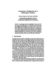
3 JMic Conception and Architecture In the following, we will present the JMic architecture, a simulator of a microprogrammable machine, written in the Java programming language. JMic is used as an acronym for Java MICroprogrammable machine. The use of java makes an integration of the simulator simpler, since Java is (mostly) a platform independent language. The learning material consists of a documentation in portable document format (PDF), a description of the simulator’s architecture, the simulator and about 40 example programs. JMic models a micro-programmable machine, i.e. a machine whose instruction set is not fixed, but can (and must) be defined by a microprogram stored in a separate memory called the microinstruction-memory. Figure 1 gives an overview over the JMic hardware architecture. We see that students have to deal with a great level of detail to understand the function of the micro-programmable machine. The significant difference to other hardware-based simulators is that the implementation of the simulator is based on elementary hardware units as we will see later. Data−BUS Address−BUS Instruction Register Memory 216 Cells
Status− Registers
ALU & Registers
a 16 bits Status
Mapping Unit Sequencer Instruction Counter Condition
Micro−Instruction−Register (80 Bits)
Micro−Instruction−Memory (4096 x 80 Bits)
Figure 1: JMIC hardware architecture
In each cycle, one microinstruction is copied into the so-called microinstruction-register whose 80-bit output controls the remaining parts of the machine comprising two 16-bit memory interconnect buses, the main memory, the arithmetic-logic-unit (ALU), the statusregisters, the (machine) instruction register, the (machine) instruction counter, and the socalled sequencer. In the following, the most important properties of each of these components will be described. For the students, a more detailed description exists, comprising about 20 pages. The main memory consists of 216=65535 memory cells, each cell being 16 bits wide. • The ALU comprises 16 general purpose registers and a Q-register, which can be used for intermediate results. The operations which can be performed by the ALU include ADD, SUB, AND, OR. It processes two operands, which can be registers, zero, or a 16-bit input of the ALU. The result can be stored into a register (if the second input operand and the result are both general purpose registers, they must be identical) or a 16-bit output of ALU. The arithmetic unit generates 4 status flags, which are send to the • Status-Register-Unit. This unit comprises two sets of status registers (Zero, Negative, Overflow, and Carry). One register is called the machine status register, being valid over several machine instructions. The other status register can be used by the microprogram for internal conditional branches. Using this register avoids an unwanted manipulation of machine-level state from within the microprogram. • The instruction register contains a copy of the first 16 bits of the current machine instruction. The format is the same for every machine instruction: it starts with an 8-bit opcode, and may then specify up to two general purpose registers (called RA and RB). • The instruction counter contains the address of the current machine instruction. It points to the memory cell whose content was copied to the instruction register. The instruction counter is able to increase its content by one, and can also load a new content. • The sequencer is responsible for choosing the next microinstruction. Depending on the current microinstruction, the address of the next microinstruction may be: 1. The address of the current microinstruction increased by one, 2. a constant given by the current microinstruction or 3. a constant given by the opcode of the machine instruction register. The next microinstruction may also be dependent on the status register. In this way, conditional branches on the micro-level can be realized, which in turn are needed to implement conditional jumps on the machine level. The microinstruction-memory usually contains the microprogram IFETCH implementing the instruction fetch and decode. In addition, a dedicated microprogramm is implemented for each opcode, to realize the remaining phases like loading and storing operands as well as performing arithmetic and logic calculations. The typical execution of a single machine instruction will be implemented by a microprogram as follows: •
1. We assume that the first microinstruction of the program IFETCH is present in the microinstruction-register. Executing this instruction will tell the main memory to start a read transaction, the instruction counter to output its content to the address bus, the ALU to do nothing, and the sequencer to load the next microinstruction. 2. The second microinstruction will terminate the read access. Hence, the memory delivers the content of the cell which was given on the address bus before, i.e. the current machine instruction. At the same time, the machine instruction register is directed to store the content of the data bus. As a result, the current machine instruction is copied into the instruction register. The sequencer loads the next microinstruction.
3. The sequencer is instructed to look at the opcode (stored in the first 8-bits of the instruction register) and choose the corresponding microinstruction, which implements this opcode. This is done by a mapping unit, which maps 8-bit opcodes to the respective 12-bit micro-addresses. At the same time, the machine instruction counter is increased by one. 4. This and the remaining steps are dependent on the current machine instruction. For example, a simple ADD may add two registers, whereas a JMP may load the instruction counter by a constant. In any case, at the end of the microprogram, a branch is made to the beginning of the microprogram IFETCH to fetch and execute the next machine instruction. The micro-programmable machine described above was implemented in hardware and as software-simulator on gate level. We first created a set of Java classes which can simulate simple combinational circuits like n-way AND, NOT and OR, as well as a simple class representing an n-bit register. These classes were designed to form more complex circuits through combination. For example, an XOR gate can be built using two AND gates, two NOTs and an OR-gate. Moreover, a half-adder can be made out of an XOR and an AND. Continuing, a full adder consists of two half-adders and an OR, and an n-bit ripple carry adder can be constructed by using n full adders (see Figure 2). XOR (=1):
halfadder (HA):
fulladder (FA):
A
&
&
B
&
A
=1
CIN
B
HA
>=1
HA
>=1 C
A3
Y
B3
A2
Y
COUT
B2
A1
B1
A0
B0 CIN
4−bit ripple carry adder
FA
COUT
FA
Y3
FA
Y2
FA
Y1
Y0
Figure 2: Different circuit hierarchies Using this methodology, we are able to implement the simulator in a hierarchic way by using Boolean gates. It is clear that such an implementation is very valuable from a didactical point of view, as students can understand how the machine works by taking a look at the source code. As Figure 3 exemplarily shows how a half-adder is implemented by using a class derived from the abstract class HBlock. // interface defining the in- and ouputs public interface IHalfAdder extends IBlock { final int A = 0; // input final int B = 1; final int Y = 0; // output final int C = 1; }
// implementation public class HalfAdder extends HBlock implements IHalfAdder{ //subblocks including branchings Branching b[] = new Branching[2]; Xor xor; And and; public HalfAdder(){ super(2,2); // 2 inputs and 2 outputs // create subblocks newSubblock(xor = new Xor()); newSubblock(and = new And(2)); newSubblock(b[0] = new Branching(2)); newSubblock(b[1] = new Branching(2)); //connect input A/B to input 0 of b[0]/ b[1] connectInput(A,b[0],0); connectInput(B,b[1],0); //internal wiring connectSubBlocks(b[0],0,and,0); connectSubBlocks(b[0],1,xor,0); connectSubBlocks(b[1],0,and,1); connectSubBlocks(b[1],1,xor,1); //connect outputs connectOutput(and,0,C); connectOutput(xor,0,Y); } }
Figure 3: Source code of a half-adder First, the subblocks are created. In this case, an AND-gate, XOR-gate with fan-in of two and two branchings are required. The input of the half-adder is connected to the respective subblocks. Then, the subblocks are connected and finally, the outputs of the half-adder are connected to the outputs of the respective subblocks. Note that feedback loops are allowed if memory units (e.g. registers) are used properly. In addition to the simulator core, JMic also comprises a sophisticated graphical user interface (see Figure 4).
Figure 4: JMic User Interface
By using this interface, it is possible to • view and modify the content of the main memory, • view and modify registers and status flags, as well as the machine instruction counter, • view and modify the content of the microinstruction-memory, • setting the current microinstruction, as well as performing single steps, or running the machine to a predefined breakpoint and • saving and loading the machine's status to/from background storage. Additionally to the simulator, about 40 example microprograms are provided to show elementary and complex operation of the underlying automaton.
4 Porting and Integrating the Lab In this Section, the platform 2003 integration of the simulator will be described. Since JMic is entirely written in the Java programming language, it is (mostly) platform independent and therefore a good candidate for vspace integration. We either have the possibility to upload the material via file transfer or via the web-interface. Then, we have to create logical links between material and the platform user interface. Logical links are dedicated links between platform content or uniform resource locators (URLs). When a new semester begins, the platform content, consisting of links and learning material is cloned automatically. A classification helps to put the material in the right logical context. In our case, the material is integrated in Additional material, which is different from Course material and Solutions to exercises. The documentation from the Technical University of Munich was in a portable document format, so a logical link was created to the uploaded documentation. Figure 5 shows the final integration of the simulator, its documentation and exercises.
Figure 5: Integrated material
5 Conclusion The benefits of vspaces are cost effectiveness, reduced need for teacher intervention, increased student interest and control, adaptability to various learning styles and rates and the automation of self-tests. In this paper, we showed the integration of traditional learning material in an existing elearning platform 2003 at the University of Hagen. A simulator of a microprogrammable automaton, developed at the Technical University of Munich was explained on a technical basis to show that the teaching of hard- and software matters does not have to be necessarily separated. By looking at the source code, hardware design and
reuse within objected-oriented programming [6] can be educated simultaneously. The presented simulation environment can be presently used more in a single-user fashion. With Cure [10], developed at the University of Hagen, we could also support collaborative work, thus having several students working in parallel on the same problem, sharing their thoughts, opinions and results for comparison.
References [1] M. W. Davidson, K. I. Tchourioukanov, and M. Abramowitz, Virtual scanning electron microscopy applet, Olympus America Inc. and The Florida State University, 1998. http://micro.magnet.fsu.edu/primer/java/electronmicroscopy/magnify1/index.html. [2] M. Duguay, The TeleLearning Experience, http://www.telelearn.ca/. [3] Virtual Laboratory, National University of Singapore (NUS), http://vlab.ee.nus.edu.sg/vlab/ [4] M. V. Goldman, Physics 2000 interactive applets, University of Colorado, Boulder, http://www.colorado.edu/physics/2000. [5] Howard Hughes Medical Institute, Virtual laboratories, http://www.hhmi.org/biointeractive/. [6] E. Gamma, R. Helm, R. Johnson, and J. Vlissides, Design Patterns: Elements of Reusable Object-Oriented Software, Addison Wesley Longman, Inc., Reading, MA, 1995. [7] O. Bendel, S. Hauske (2004): E-Learning: The dictionary. Oberentfelden/Aarau, 2004 ISBN 3-0345-0111-0. [8] B. Kleimann, K. Wannemacher: E-Learning at German Universities. From Project Development to Sustainable Implementation. Hannover: HIS 2004 (HIS-Hochschulplanung, Vol. 165). ISBN 3-930447-61-4. (German version: B. Kleimann, K. Wannemacher: ELearning an deutschen Hochschulen. Von der Projektentwicklung zur nachhaltigen Implementierung. Hannover: HIS 2004. ISBN 3-930447-56-8). [9] http://www.izhd.uni-hamburg.de/pdfs/Plattformen.pdf. [10] J. Haake, T. Schümmer, M. Bourimi, B. Landgraf, A. Haake, CURE – Eine Umgebung für selbstorganisiertes Gruppenlernen, i-com Zeitschrift für interaktive und kooperative Medien 3(2), pp. 20-26, 2004.