International Journal of Precision Engineering and Manufacturing Vol. 5, No.4, October 2004.
Position Control of an AC Servo Motor Using Sliding Mode Controller with Disturbance Estimator Jung-Woo Cheon1, Seung-Bok Choi1,#, Hyun-Jeong Song1 and Joon-Ho Ham1 1
Department of Mechanical Engineering, Inha University, Incheon, South Korea
ABSTRACT In this work, a new control methodology to achieve accurate position control of an AC servo motor subjected to external disturbance is proposed. Unlike conventional sliding mode controller which requires a prior knowledge of the upper bound of external disturbance, the proposed technique, called sliding mode controller with disturbance estimator (SMCDE), can offer robust control performances without a prior knowledge of the disturbance bound. The SMCDE is featured by an integrated average value of the imposed disturbance over a certain sampling period. By doing this, undesirable chattering phenomenon in the estimation process can be effectively alleviated. The benefits of the proposed control methodology are empirically demonstrated on AC servo motor and control responses are evaluated through a comparative work between the proposed and conventional control schemes. Key Words : Sliding Mode Control, Disturbance Estimator, Robust Control, Position Control, AC Servo Motor
1. Introduction It is well-known that an AC servo motor can be effectively utilized in many position control systems subjected to external disturbances such as friction.1,2 The conventional PID controller can guarantee robust and favorable control performances if accurate dynamic model and detailed information on the disturbances are acquired. 3,4 However, this assumption is hardly acceptable in practical environment. This leads to use so called robust control techniques such as sliding mode control (SMC). 5-8 The SMC is a special class of nonlinear control mechanism characterized by a discontinuous control action which changes the structure upon reaching a set of sliding surfaces. During the motion on the sliding surface (sliding phase), the system has invariance properties, yielding motion that is ☞
Manuscript received: April 12, 2004 ; Accepted: June 2, 2004
#
Corresponding Author: Email :
[email protected] Tel : +82-32-860-7319, Fax:+82-32-868-1716
independent of certain perturbations including external disturbances. In most of the SMC design strategies, the use of over-conservative high feedback gain is inevitable since the upper bound of the perturbation is normally employed to guarantee robust control performance. However, this causes undesirable chatter problem which deteriorates control accuracy. Recently, various techniques for perturbation estimation in SMC, which offer robust control performance without a prior knowledge about the upper bounds of the perturbations, have been proposed to avoid the over-conservative design.9-13 Kozek et al.9 proposed a sliding mode controller associated with a linear disturbance observer and proved its effectiveness by applying it to the levitation system of high-speed electromagnetic vehicles. Lu and Chen10 proposed a perturbation estimator using the theory of the variable structure system to enhance the robustness of a pole placement controller design. Liu and Peng11 developed a disturbance observer by treating plant non-linearities and parameter variations as a lumped disturbance and showed its superior performance to the standard adaptive control scheme. Elmali and Olgac12 proposed a very effective methodology, called sliding 14
J.-W. Cheon, S.-B. Choi, H.-J. Song and J.-H. Ham : International Journal of Precision Engineering and Manufacturing Vol.5, No.4.
mode control with perturbations estimation (SMCPE), which offers a robust feedback control with much lower gains than its conventional counterparts. This method has been successfully implemented on a two-axis planar SCARA robot.13 The disturbance estimator proposed in this work has a similar form to the SMCPE. However the proposed one does not include state derivative terms (included in the SMCPE) which may cause undesirable noise and chattering in the estimation process. Instead, the integrated average value of the imposed disturbance is used over a certain sampling period to avoid the noise and chattering phenomena. In order to demonstrate the proposed controller, called sliding mode controller with disturbance estimator (SMCDE), AC servo motor subjected to torque disturbances is adopted and its position control performances are experimentally evaluated through a comparative work between conventional SMC and the proposed SMEDE.
2. Controller Design
e1(t ) = xd (t ) − x1(t )
where xd (t )is the desired angular displacement of the motor. Thus, a sliding surface (in fact, a line in this case) is established in the error state as
s(t ) = c1e1 (t ) + e2 (t ) = 0
(t ) + e&2 (t ) s&(t ) = c1e& 1 = c1e& (t ) + & x& (t ) + 1 d
(1)
x&2 (t ) = −
B 1 x& 1 (t ) + u (t ) + d (t ) J J
(2)
where u (t ) is the input torque to be applied to the motor, and x1 (t ) and x2 (t ) represent angular displacement and velocity of the motor, respectively. Since the impending control issue is to achieve desired position and velocity of the motor, the tracking errors are defined by
B 1 x2 (t ) − u(t ) − d (t ) J J
(5)
Now, we can construct the following SMC which satisfies the sliding mode condition.
where J is the moment of inertia of the motor, B is the effective viscous damping coefficient, Tm (t ) is the input torque and d (t ) is the external torque including the friction. In order to formulate the proposed SMCDE, Eq.(1) can be rewritten in a state space form as follows:
x& 1 (t ) = x2 (t )
(4)
where c1 (> 0) is the slope of the sliding surface. It can be seen that the error state converges to zero for any initial conditions provided that a control law u (t ) exists in Eq.(2) so as to cause the trajectory e(t ) to slide along the surface defined by Eq.(4). This can be achieved by constructing an appropriate SMC to satisfy the sliding mode condition : s (t ) s&(t ) < 0 . To formulate such an SMC, the dynamics of the sliding surface is firstly obtained by
The governing equation of the AC servo motor adopted in this work can be expressed as follows:14 ⎡0 1 ⎤ ⎡θ ⎤ ⎡ 0 ⎤ ⎡θ& ⎡0 ⎤ m⎤ = ⎢ B ⎥ ⎢ m ⎥ + ⎢ 1 ⎥Tm (t ) + ⎢ ⎥ d (t ) ⎥ ⎢& & 0 & − θ ⎣1⎦ ⎣⎢θ m ⎦⎥ ⎢⎣ J ⎥⎦ ⎣ m ⎦ ⎢⎣ J ⎥⎦
(3)
e2 (t ) = x&d (t ) − x2 (t )
u (t ) = J (ueq + k sgn( s (t ))), k > d (t ) ueq = c1e& x& 1 (t ) + & d (t ) +
B x2 (t ) J
(6)
where k is the discontinuous control gain. As we noticed from Eq.(6) that the information on the disturbance d (t ) should be known in advance in order to determine an appropriate control gain k . However, an accurate knowledge of the upper bounds of the disturbance may not be easy to obtain in practice. This may yield the over-conservative high feedback gain, which results in undesirable control performances such as high chattering. Consequently, an accurate estimation of the disturbance is necessary to enhance control performances. In order to design the proposed SMCED, the s(t)
15
J.-W. Cheon, S.-B. Choi, H.-J. Song and J.-H. Ham : International Journal of Precision Engineering and Manufacturing Vol.5, No.4.
dynamics, which includes the disturbance estimator, is arranged as follows: s&(t ) = c1e& 1 (t ) + e&2 (t ) B x2 (t ) − J u eq (t ) − k sgn( s(t )) + d estimated (t ) − d (t )
= c1e& x& 1 (t ) + & d (t ) +
The last term of the above equation compensates for the correction of the error which may be caused by an B ueq (T − δ ) = c1e& x& assumption ; In 1(t ) + & d (t ) + x2 (t ) . J computation, it is hard to accurately calculate this term. Thus, the following approximation is used :
(
(7)
The integration of the above equation from T − δ to T yields
d average (T ) = − {s (T ) − s (T − δ )} δ −
T
k sgn( s (T − δ )) + d estimated (T − δ ) −
δ ⋅ k sgn( s(T − δ )) + δ ⋅ d estimated (T − δ ) +
∫
B ⎛ & ⎞ x& ⎜ c1e1 (t ) + & d (t ) + x2 (t ) − u eq (T − δ ) ⎟dt T −δ ⎝ J ⎠
(12)
Now, by substituting Eq.(12) into Eq.(11) we can obtain a final from of the average disturbance as follows:
∫T −δ d (t ) dt = −{s(T ) − s(T − δ )}− T
)
X c (T ) = − ueq (T ) − ueq (T − δ ) 2
X c (T )
(8)
In the above, δ is the sampling time for the disturbance estimation. Both control and estimation performances, of course, depend upon the sampling time of δ . A constant, d average , is now defined as in the left-hand side of Eq.(8) :
(13)
The calculated value for Eq.(13) is the average disturbance integrated from T − δ to T , and the disturbance estimation is fed back for the next step of control input. In computer realization, the disturbance estimation d estimated (t ) can be obtained by the Taylor series as n
(i ) d estimated (t ) = ∑ δ i ⋅ d average (T ) i ! T
∫ T −δ
d average (T )dt =
T
∫T −δ
i =0
(14)
d (t ) dt (9)
where i is the design of time derivative. Thus, the SMCDE proposed in this work can be expressed by The above equation indicates that the integrated value of the disturbance is equal to the integrated value of average disturbance daverage(T ) . Thus, the average disturbance can be expressed by
daverage(T) =
T
∫ T−δ d(t)dt δ
(10)
{
k sgn( s (T − δ )) + d estimated (T − δ ) + ⎧T ⎛ B ⎞ ⎫ x& ⎨ ∫ T −δ ⎜ c1e& 1 (t ) + & d (t ) + x2 (t ) − ueq (T − δ ) ⎟dt ⎬ δ J ⎝ ⎠ ⎭ ⎩
(11)
(15)
Consequently, the realization of the proposed SMCDE can be achieved by combining Eqs.(13), (14) and (15).
3. Control Results
Substituting Eq.(10) into the left-hand side of Eq.(8) yields the following equation: d average (T ) = − {s (T ) − s (T − δ )} δ −
}
u (t ) = J ueq (t ) + k sgn( s (t )) − d estimated (t )
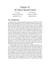
In order to demonstrate the effectiveness and superior performance of the proposed SMCDE, an experimental apparatus has been established as shown in Fig.1. The angular displacement of the motor is measured by the optical encoder and fed back to the microprocessor (IBM PC). On the other hand, the angular velocity of the motor, which is required for the controller implementation, is
16
J.-W. Cheon, S.-B. Choi, H.-J. Song and J.-H. Ham : International Journal of Precision Engineering and Manufacturing Vol.5, No.4.
IBM PC Encoder Counter
imposed and control results are presented in Fig.4 and 5, respectively. It is also observed that the proposed SMCDE provides more accurate control responses than conventional SMC under relatively high frequency of the external disturbance. As mentioned earlier, control response of the proposed SMCDE depends upon the sampling time for the estimation. Table 1 presents the
60
Proposed SMCDE Conventional SMC
40
2
30
1
Error(deg)
Angle(deg)
50
20
0
0
-1
10
-2 2.0
0
1
2
2.1
2.2
3
2.3
2.4
2.5
4
5
Time(sec) 0.35 Proposed SMCDE Conventional SMC
Input Torque(Nm)
0.30 0.25 0.20 0.15 0.10 0.05 0.00
-0.05
0
1
0.04
Disturbance(Nm)
numerically obtained by tracking time derivative of the angular displacement. Both the displacement and velocity signals are fed back to the microprocessor via the A/D converter. And the control input determined from the SMCDE given by Eq.(15) is supplied to the motor via the D/A converter. It is to be noted that actual input to the motor is not voltage, but current into which voltage is converted through the servo drive board of the motor. The model parameters and controller gains employed in this work are given as follows : J = 0.00268kg ⋅ m2, B = 0.0347568Nm ⋅ s, c = 0.29481, k = 0.2, δ = 0.001 sec. For the dynamic motion, the motor shaft initially positioned at 0° was rotated to the position of 45° and steadily regulated. It is here remarked that the disturbance torque is augmented to the input torque during control action. Figure 2 presents the simulated control responses when the external disturbance , 0.02 sin(9.5 Hz t ) , is imposed on the input torque. It is clearly seen that the imposed disturbance is accurately estimated by the proposed SMCDE, and this results in superior control performance to the conventional SMC. Figure 3 presents the measured control responses under the same conditions imposed on the results shown in Fig.2. It is observed that the small magnitude of the estimation error has been occurred at the peak of the sinusoidal trajectory. This is due to system uncertainties including the motor friction. Despite the error, the regulating control performances of the proposed SMCDE guarantees acceptable position accuracy. In order to investigate the effect of the disturbance dynamics on control responses, the following two disturbances ; 0.02 sin(30 Hz t ) and 0.02 sin(60 Hz t ) are
Motor Driver AC Servo Motor
D/A Converter
2 3 Time(sec)
4
5
Real Disturbance Estimated Disturbance
0.02 0.00
-0.02 -0.04 1.0
Fig. 1 Photograph of an experimental apparatus
1.1
1.2 1.3 Time(sec)
1.4
Fig. 2 Simulated control responses in the presence of the torque disturbance (9.5Hz)
17
1.5
J.-W. Cheon, S.-B. Choi, H.-J. Song and J.-H. Ham : International Journal of Precision Engineering and Manufacturing Vol.5, No.4.
average disturbance error with several different sampling times. As expected, the estimation error increases as the sampling time increases. This directly indicates that the higher resolution of the microprocessor yields the higher accuracy of the position control.
4. Conclusions In this work, a new type of sliding mode controller with
60 Proposed SMCDE Conventional SMC
Angle(deg)
40
3 2
30
Error(deg)
Angle(deg)
50
20
1 0 -1
δ 0
-3 2.0
1
2.1
2.2
2 3 Time(sec)
2.3
2.4
2.5
4
5
1.0
20
0.0 -0.5 -1.0 -1.5 2.0
0
1
0.25
2.1
2 3 Time(sec)
2.2
2.3
2.4
2.5
4
5
Proposed SMCDE Conventional SMC
0.03 Torque(Nm)
0.02
0.20 0.15 0.10
0.01 0.00
-0.01
0.05
-0.02
0.00
-0.03 0
1
2
3
4
-0.04 2.0
5
2.1
Time(sec)
2.3
2.4
2.5
Real Disturbance Estimated Disturbance
0.04 Torque(Nm)
0.02 0.00
-0.02
0.02 0.00
-0.02
-0.04 -0.06 1.0
2.2
Time(sec)
Real Disturbance Estimated Disturbance
0.04 Disturbance(Nm)
0.5
0.04 Proposed SMCDE Conventional SMC
0.30 Input Torque(Nm)
1.5
30
0
0.35
-0.05
40
10
-2
10
Proposed SMCDE Conventional SMC
50
Error(deg)
60
0
disturbance estimator (SMCDE) was proposed and applied to the position control of AC servo motor. After explaining the salient feature of the SMCDE, a controller to achieve accurate position of the servo motor has been designed in a sequential manner. The controller was then experimentally realized with respect to different disturbance frequency components and sampling times for the estimation. It has been demonstrated that control responses of the SMCDE are far superior to those
-0.04 1.1
1.2 1.3 Time(sec)
1.4
Fig. 3 Measured control responses in the presence of the torque disturbance (9.5Hz)
1.5
1.0
1.1
1.2
1.3
1.4
Time(sec)
Fig. 4 Measured control responses with different disturbance frequencies(30Hz)
18
1.5
J.-W. Cheon, S.-B. Choi, H.-J. Song and J.-H. Ham : International Journal of Precision Engineering and Manufacturing Vol.5, No.4.
Table 1 Average disturbance error for each sampling time Sampling Time(δ) Average Disturbance Error(%)
0.0005
0.001
0.005
0.01
0.000003 %
0.01 %
0.06%
0.5%
obtained from the conventional sliding mode controller which does not have the disturbance estimator. It has also been investigated that control accuracy of the SMCDE is sensitive to the estimation sampling time. It is finally remarked that the proposed control methodology can be directly applied to various control systems (for example, robotic system) subjected to external disturbances or uncertainties.
References
60 Proposed SMCDE Conventional SMC
40
1.5 1.0
30 Error(deg)
Angle(deg)
50
20
0.0 -0.5 -1.0
10 0
0.5
-1.5 2.00
0
1
2
2.05
3
2.10
2.15
2.20
4
5
Time(sec) 0.2 Proposed SMCDE Conventional SMC
Torque(Nm)
0.1 0.0
-0.1 -0.2 2.0
2.1
2.2
2.3
2.4
2.5
Time(sec) 0.15
Real Disturbance Estimated Disturbance
Torque(N.m)
0.10 0.05 0.00 -0.05 -0.10 -0.15 1.0
1.1
1.2 1.3 Time(sec)
1.4
1.5
Fig. 5 Measured control responses with different disturbance frequencies (60Hz)
1. Choi, S. B. and Cheong, C. C., "A Robust Tracking Control for Robotic Manipulators Using Sliding Modes," Journal of the Korean Society of Precision Engineering, Vol. 9, No. 1, pp. 18-22, 1992. 2. Lee, J. H., Ko, J. S., Chung, S. K., Lee, J. J. and Youn, M. J., "Design of Continuous Sliding Mode Controller for BLDD Motor with Prescribed Tracking Performance," IEEE Transactions on Automatic Control, pp. 770-775, 1992. 3. Weibing, G. and James, C. H., "Variable Structure Control of Nonlinear Systems : A New Approach," IEEE Transactions. Ind. Electron. Vol. 40, No. 1, pp. 45-55, 1993. 4. Gomes, S. C. P. and Chretien, J. P., "Dynamic Modeling And Friction Compensated Control of A Robot Manipulator Joint," Proceedings of the IEEE International Conference on Robotics and Automation, pp. 1429-1435, 1992. 5. Utkin, V. I., "Variable Structure System with Sliding Modes," IEEE Transactions on Automatic Control, Vol. AC-22, No. 2, pp. 212-222, 1977. 6. Choi, S. B., Park, D. W. and Jayasuriya, S., "A TimeVarying Sliding Surface for Fast and Robust Tracking Control of Second-Order Uncertain Systems," Automatica, Vol. 30, No. 5, pp. 899-904, 1994. 7. Young, K. D., Utkin, V. I. and Ozguner, U., "A Control Engineer's Guide to Sliding Mode Control," Control Systems Technology, IEEE Transactions, Vol. 7, pp. 328-342, 1999. 8. Park, D. W. and Choi, S. B., "Moving Sliding Surfaces for High-Order Variable Structure Systems," International Journal of Control, Vol. 72, pp. 960-970, 1999.
19
J.-W. Cheon, S.-B. Choi, H.-J. Song and J.-H. Ham : International Journal of Precision Engineering and Manufacturing Vol.5, No.4.
9. Kozek, M., Puchhammer, G. and Jorgl, M. P., "A MIMO Sliding Mode Control for a High Speed EMS MAGLEV-Vehicle using Disturbance Estimation," Proceedings of the 1994 IEEE International Conference on Robotics and Automation, pp. 587592, 1994. 10. Lu, Y. S. and Chen, J. S., "Design of a Perturbation Estimator Using the Theory of Variable-Structure Systems and Its Application to Magnetics Levitation Systems," IEEE Transactions on Industrial Electronics, Vol. 42, No. 3, pp. 281-289, 1995. 11. Liu, C. S. and Peng, H., "Disturbance Observer Based Tracking Control," ASME Journal of Dynamic Systems, Measurement, and Control, Vol. 122, No. 2, pp. 332-335, 2000. 12. Elmali, H. and Olgac, N., "Sliding Mode Control with Perturbation Estimation (SMCPE) : A New Approach," International Journal of Control, Vol. 56, No. 4, pp. 923-941, 1992. 13. Elmali, H. and Olgac, N., "Implementation of Sliding Mode Control with Perturbation Estimation (SMCPE)," IEEE Transaction on Control System Technology, Vol. 4, No. 1, pp. 79-85, 1996. 14. Kim, J. H., Eun, Y. S. and Cho, D. I., "Variable Structure Control of AC Servo Motors for Performance and Robustness Improvement," KACC, pp. 515-518, 1995.
20