SELECTED TOPICS in SYSTEM SCIENCE and SIMULATION in ENGINEERING
Torque Control for DC Servo Motor Using Adaptive Load Torque Compensation CHANYUT KHAJORNTRAIDET
JIRAPHON SRISERTPOL
School of Mechanical Engineering, Institute of Engineering, Suranaree University of Technology Address: Nakhon Ratchasima 30000 THAILAND
[email protected]
Abstract: - A torque control system is an important process in industries. The value of torque which is generated by DC servomotor depends upon a motor current. Since the torque control system uses the estimated current from an observer, it will receive an effect from torque disturbance (load torque) during an operation. The incorrect estimated current from the observer affects a current feedback signal. This paper presents a technique for torque control of DC servomotor by using adaptive load torque compensation. The load torque can be compensated to the observer, the result show that the estimated current error from the observer is reduced. Therefore, this method can be applied to improve an efficiency of the torque control system and estimate the load torque of DC servomotor. Key-Words: - Adaptive compensation, Observer, and Torque control system
1
Introduction
2
The DC servomotors are widely used for a variety of actuator applications. When a system interacts with the environment, it will receive disturbance from load torque. The torque control system is an important system to control a force when the system interacts with the environment during the task [1]. The output torque of the motor is proportional to the input current. The torque control method, is used direct current control, is degraded by disturbance torque in the actuator [2]. There are many applications where the load torque fluctuates and a fluctuating load torque should be considered to maintain a constant speed in the drive machines [3-4]. For the servo application, significant parameter variations are often arising by unknown loads [5]. Generally, the load torque of a DC servomotor is difficult to measure in practice but it can be estimated. The Lyapunov’s direct method is a high performance to estimate the DC motor load torque [6]. The load compensation method which is composed of deadbeat observer is well-known method [7]. Lyapunov theory is a well know method that guarantee the stability of adaptive algorithms for adjusting parameters in adaptive systems [8]. This paper describes method to control torque of DC servomotor using adaptive load torque compensation. The simulation results show that the method can be used to improve the efficiency of DC servomotor torque control system under loading condition and estimate load torque of the system.
ISSN: 1792-507X
Mathematical Descriptions
The permanent magnet DC motor is used to acquire data as a DC servo motor. The torque control system of DC motor is controlled by the armature current (ia). The speed of the system is depended on armature voltage (Va) when the field current is held constant. An armature circuit is shown in Figure 1. The differential equations of the armature controlled are as follows:
I ωɺ = −bω + Tm − TL
(1)
dia + Ra ⋅ ia dt where Vb = K b ⋅ ω and Tm = K t ⋅ ia Va − Vb = La
(2)
Fig. 1 Armature Circuit where I is the moment of inertia (kg·m2), Kt is the torque constant (N·m/A), Kb is the electromotive force constant (V·s/rad), TL is the load torque (N·m), b is the linear approximation of viscous friction (N·m·s/rad), Ra is the resistance ( Ω ), La is the inductance (H), ia is the
454
ISBN: 978-960-474-230-1
SELECTED TOPICS in SYSTEM SCIENCE and SIMULATION in ENGINEERING
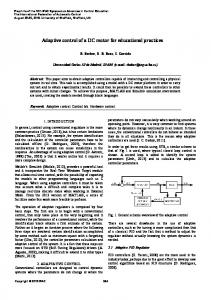
armature current (A), ω is the angular velocity (rad/s), Va is the armature voltage (V), Vb is the back EMF (V) In the servo applications, the unknown load is a significant parameter. The propose scheme for DC servomotor torque control is shown in Figure 2. The outer loop controller is designed to achieve a fast and accurate response under loading operation.
A PI controller is used in outer loop control. The current of the observer is feedbacked to the torque control system before it is conversed to torque of the motor. The equation of PI controller is shown in Eq.5. K (5) GPI = K p + i s 2.4 Adaptive Load Torque Compensation of Control System An adaptive system can self-modify to compensate the load torque of the observer automatically to accommodate changes. Consider the DC servomotor system with the variable torque. The equation of DC servomotor in second order form is R b R b K K Kt Va = ωɺɺ + a + ωɺ + a + b t ω La I L I La I a La I R 1 + TɺL + a TL I La I
Fig. 2 DC servomotor torque control system 2.1 Full-Order State Observer Design
Equation (6) can be rewritten as
A cost and a complexity of the control system increase as the number of required sensor increases. A state observer can be designed to estimate the state variables of DC servomotor via angular velocity measurement. Fortunately, if the system is completely observable, then it is possible to estimate the states that are not measured. The equations of full-order observer are I ωˆɺ = −bωˆ + Kt iˆa − TL + L1e ɺ La iˆa = Va − Ra ⋅ iˆa − K bωˆ + L2 e
ɺɺ + a2ωɺ + a1ω + α 2TɺL + α1TL b1 Va = ω
(7)
Introducing new parameters defined by R b K K R b Kt , a1 = a + b t , a2 = a + La I L I L I a a La I R 1 α1 = a , α 2 = La I I
b1 =
(3)
The equation of full-order state observer in second order form is
(4)
R b R b K K Kt Va = ωɺɺˆ + a + ωɺˆ + a + b t ωˆ La I La I La I La I R 1 ɺ + TˆL + a TˆL I La I
where L1 and L2 are the observer gains, (^) is the estimated state and an error is e = ω − ωˆ . 2.2 Current Control Loop Since an inner loop controller of the system is operated by a current feedback from the motor system, the output torque of the motor is a proportion of the motor current. A block diagram of current controlled loop is shown in Figure 3. In practice, the torque control system will uses the current feedback from the observer in current control loop. The GI is the integral in the inner loop control (GI=1/s).
(8) When we known the value of system parameter exactly, the equation (8) can be simplified, yielding ɺ (9) b1 Va = ωɺɺˆ + a2ωˆɺ + a1ωˆ + α 2TˆL + α1TˆL From equation (7) and (9) the error between the plant and the observer is described by ɺ eɺɺ = −a2eɺ − a1e − α2 (TɺL − TˆL ) − α1 (TL − TˆL )
(10) Lyapunov’s direct method: Lyapunov function is selected as a eɺ 2 1 ɺ ɺˆ 2 ɺ V (e, eɺ, TˆL , TˆL ) = 1 e2 + + (TL − TL ) 2 2 2γ 2
Fig. 3 Current control loop
+
1 (TL − TˆL ) 2 2γ 1
(11)
2.3 Outer Loop Controller
ISSN: 1792-507X
(6)
455
ISBN: 978-960-474-230-1
SELECTED TOPICS in SYSTEM SCIENCE and SIMULATION in ENGINEERING
where γ 1 and γ 2 are adaptive gains. Then, we get the time derivative of V as
received the disturbance torque because of the incorrect estimated current from the observer. Therefore, the adaptive load torque compensator was be used to compensate load torque to the observer. The result of torque compensation to the torque control system is shown in Figure 5 and 6.
ɺ dV 1 ɺ dTˆ ɺɺɺ + (TɺL − TˆL ) − L = a1eeɺ + ee dt γ2 dt ˆ dT 1 + (TL − TˆL ) − L γ1 dt
Load Disturbance 0.12
(12) 0.1
ɺ 1 dTˆL dV ɺ = − a2 eɺ 2 + (TɺL − TˆL )(− − eɺα 2 ) dt γ 2 dt 1 dTˆL + (TL − TˆL )( − − eɺα1 ) γ 1 dt
0.08
Load Torque (N.m)
Using equations (10) and (12), we obtain
0.06
0.04
(13) 0.02
ɺ When the rates of change of TˆL and TˆL are
0
ɺ dTˆL = −γ 2 eɺα 2 dt dTˆL = −γ 1eɺα1 dt
0
5
10
15
20
25
Time (sec)
Fig. 4 Disturbance torque 0.25
(14)
Thus
0.2 Desired torque Output torque
(15) Torque (N.m)
dV = − a2eɺ 2 dt
The time derivative of Lyapunov function (V ) is negative semi-definite. The stability of the system will be stable.
0.15
0.1
0.05
3 Simulation Results
0
This section demonstrated the simulation result of DC servomotor torque control system when the system and controller parameters are as follow:
0
2
3
4
5 6 Time (sec)
7
8
9
10
Fig. 5 Dynamic response of torque control in the case of the step function input with load torque compensation
I = 1.4 × 10⁻⁵ kg ⋅ m 2 / rad , Kt = 0.052 N ⋅ m / A
0.6
Kb = 0.057 V ⋅ s / rad , b = 1.0 ×10⁻⁶ N ⋅ m ⋅ s / rad
0.58
Ra = 2.5 Ω , La = 2.5 × 10⁻³ H
0.56
K p = 80 A / N ⋅ m, Ki = 2.5 ×10³ A / N ⋅ m
0.54 Torque (N.m)
The simulation of the torque control system was be applied the disturbance torque as the step function, as shown in Figure 4. In the simulation, there were three patterns of desired inputs. The first pattern of desired input was the step function. Then, the desired input was the ramp function. Finally, the step and ramp functions were combined as the process of torque screw driver. If no load torque interacted with the system, the torque control system which used estimated current from the observer has high efficiency to control the output torque. On the other hand, an error between the desired torque and the output torque was occurred when the system
ISSN: 1792-507X
1
0.52 0.5 Desired torque Output torque
0.48 0.46 0.44 0.42 0.4
4
4.2
4.4
4.6
4.8
5 5.2 Time (sec)
5.4
5.6
5.8
6
Fig. 6 Dynamic response of torque control in the case of the ramp function input with load torque compensation
456
ISBN: 978-960-474-230-1
SELECTED TOPICS in SYSTEM SCIENCE and SIMULATION in ENGINEERING
load torque of DC servomotor system and improved the efficiency of the torque control system.
For the control process of the torque screw driver, in the case of no-load operation PI controller can control the output torque of DC servomotor by using current feedback from the observer as shown in Figure 7.
0.6
0.6 0.5 0.5 desired torque output touque Torque (N.m)
0.4
Torque (N.m)
0.4
0.3
Desired torque Output torque
0.3
0.2 0.2 0.1 0.1 0 0
0
5
10
15
20
25
Time (sec) 0
5
10
15
20
25
Fig. 9 Dynamic response of torque control in the case of load operation with load torque compensation
Time (sec)
Fig. 7 Dynamic response of torque control in the case of no-load operation
Acknowledgement When the DC servomotor system receives disturbance torque during the operation, the state variable which is estimated form the observer was incorrect. If the incorrect estimated current is used to control torque of the system, the output torque was mistake. The result is shown in Figure 8.
The authors would like to thankfully acknowledge the research grant from Suranaree University of Technology (SUT). References: [1] Keneko, K., Komoriya, K., Ohnishi, K., and Tanie, K., “Accurate Torque Control for a Geared DC Motor based on an Acceleration Controller”, Proceeding of IEEE IECON.1992 ,Vol.1 , 1992, p.395-400. [2] Maekawa, H. “Compact servo driver for torque control of DC-servo motor based on voltage control”, Proceeding of IEEE ASME International Conference on Advanced Intelligent Mechatronics, 1999 , p.341-346. [3] N. Barakat, and R. Rajagopalan, “Speed Control of a DC Motor Using a Feedforward Computed Torque Control Scheme”, Proceeding of IEEE International Symposium On Intelligent Control, 1996, P.432-437. [4] Iwasaki, M.; Matusi, N., “Robust Speed Control of IM with Torque Feedforward Control”, Proceeding of IEEE Transactions on Industrial Electronics, Vol.40, 1993, p.553-560. [5] Phongsak Phakamach, “Control of a DC Servomotor Using Fuzzy Logic Sliding mode Model Following Controller”, Proceeding of world Academy and Science, Engineering and Technology , Issue 60, 2009, p. 504-509. [6] Srisertpol, J., and Khajorntraidet C., “Estimation of DC Motor Variable Torque Using Adaptive Compensation”, Proceeding of Chinese Control and Decision Conference, 2009, p.712-717. [7] Jong-Sun Ko, Kyu-Gyeom Kim, Yong-Jae Lee, and In Dong Kim, “Precision Speed Control of PMSM using Disturbance Observer and System Parameter
0.6
0.5
Desired torque Output torque
Torque (N.m)
0.4
0.3
0.2
0.1
0
0
5
10
15
20
25
Time (sec)
Fig. 8 Dynamic response of torque control in the case of load operation without load torque compensation After compensate the estimated load torque form the adaptive compensator to full-state observer, the error of estimated current was reduced. The response of torque control system is shown in Figure 9.
4 Conclusion The feedback of the torque control system depends on the estimated current from the observer. The load torque is also affected to quality of estimated current. This paper is demonstrated advantage of the adaptive compensation technique that can be applied to estimated
ISSN: 1792-507X
457
ISBN: 978-960-474-230-1
SELECTED TOPICS in SYSTEM SCIENCE and SIMULATION in ENGINEERING
Compensator”, Proceeding of IEEE Power Electronics Specialist Conference, Vol. 1, 2003, p. 251-255. [8] Karl J. Astrom and Bjorn Wittenmark, Adaptive Control. (2nd Edition), USA, Addison Wesley, 1995.
ISSN: 1792-507X
458
ISBN: 978-960-474-230-1