3520
JOURNAL OF LIGHTWAVE TECHNOLOGY, VOL. 30, NO. 22, NOVEMBER 15, 2012
Positioning Error Reduction Technique Using Spectrum Reshaping for Distributed Fiber Interferometric Vibration Sensor Shangran Xie, Min Zhang, Yanhe Li, and Yanbiao Liao
Abstract—A novel positioning error reduction technique is proposed for dual Mach-Zehnder fiber interferometric distributed vibration sensor. The 3 dB bandwidth of the power spectrum of interference signal is broadened to reduce the mean square error (MSE) of the cross-correlation based positioning algorithm. A high-pass filter (HPF) whose cutoff frequency is larger than the upper frequency of signal 3 dB bandwidth is applied to reshape the original power spectrum by attenuating the magnitude of low-frequency mainlobe to the same order as that of the small high-frequency components. The usage of HPF can cause bandwidth broadening and signal to noise ratio (SNR) reduction, the influence of both effects on ultimate positioning MSE are analyzed in detail. Theoretical analysis shows that there exists a valid region for the cutoff frequency of the HPF within which the contribution of bandwidth broadening dominates the process. The technique is also experimentally verified and analyzed by field test on an installed submarine cable between two islands of Zhejiang Province, China. Field test results coincide with the theoretical predictions and show that a maximum of 7 dB reduction of positioning MSE can be achieved when optimal cutoff frequency of HPF is used. Index Terms—Distributed vibration sensor, cross correlation, dual Mach-Zehnder interferometer, time delay estimation.
I. INTRODUCTION
D
ISTRIBUTED fiber optic vibration sensor has shown great potential in the applications of pipeline leakage detection, intrusion detection and structure health monitoring (SHM). Compared with other candidates, e.g., polarization optical time domain reflectometry (POTDR) [1]–[3], phase-OTDR [4], [5], coherent-OTDR [6], interferometric sensor has been successfully applied in variety of cases [7]–[11] due to its quick response, system simplicity (only CW light is required) and accurate positioning ability. Normally this type of vibration sensor utilizes two interferometers (typically both Mach-Zehnder or Michelson) with common arms and opposite lightwave propagating directions to simultaneously detect the phase change induced by vibration then calculate the arrival time difference of the two channel interference outputs by using time delay estimation (e.g., cross-correlation) algorithm [10], [11]. Due to the fast speed of lightwave, in most cases the corresponding time delay is fairly short (typically tens of s for Manuscript received May 08, 2012; revised July 17, 2012, September 17, 2012; accepted September 22, 2012. Date of publication September 28, 2012; date of current version November 16, 2012. This research is supported by National Science and Technology Pillar Program (2007BAE19B04). The authors are with Department of Electronic Engineering, Tsinghua University, Beijing 10080, China (e-mail:
[email protected]). Color versions of one or more of the figures in this paper are available online at http://ieeexplore.ieee.org. Digital Object Identifier 10.1109/JLT.2012.2221078
kilometers long sensing fibers), which greatly challenges the positioning algorithm of the sensor. Recently we developed a positioning error prediction theory for the cross-correlation based time delay estimation algorithm of dual Mach-Zehnder interferometric distributed vibration sensor [10]. The theory shows that the positioning error is determined by both signal to noise ratio (SNR) and bandwidth : when SNR is lower than a observation-time product specific threshold, the positioning mean square error (MSE) increases dramatically with SNR reduction, i.e., SNR is the dominant factor within this regime; when SNR is larger than product plays a dominant role, accurate posithe threshold, tioning result can be obtained only if the signal has large enough product, typically larger than 100 [12]. However in some applications, e.g., in the cases of submarine cable security and perimeter security with buried cables, the detected interference signal is intrinsically with narrow-bandwidth as well as short observation time due to environmental limitations, e.g., the low resonant frequencies of seabed and submarine cable, the acoustic wave attenuation caused by the soil, etc. In these cases, the value product can be one or two orders of magnitude smaller of than that is required, then small amount of noises can lead to intolerable large positioning error. Although most of the system noises can be removed by properly designing the de-noising filter, there is not much room to further improve system SNR as some noises are intrinsically hard to be eliminated, e.g., the broad-band additive circuit noise [13], the polarization fading induced visibility and phase noises varied with time and environmental condition [14], [15]. Therefore the intrinsic property product has become the bottleneck of the further of small reduction of positioning error in those applications. To solve this problem, in this paper we propose a novel pre-processing technique before cross-correlation calculation in purpose of broadening the 3 dB signal bandwidth using spectrum reshaping. A high-pass filter (HPF) is applied to enhance the weight of small high-frequency components of original power spectrum. When the magnitudes of the low-frequency components of the filtered signal are attenuated to the same order as that of the small high-frequency ingredients, the broadened bandwidth is achieved. In Section II, the influences of both bandwidth broadening and SNR reduction caused by the usage of HPF on ultimate positioning MSE are theoretically analyzed. A valid region is provided for the cutoff frequency of HPF within which the contribution of bandwidth broadening dominates the process. In Section III, field test results are proposed to further discuss the effectiveness as well as the repeatability of the technique. In Section IV, conclusions are drawn.
0733-8724/$31.00 © 2012 IEEE
XIE et al.: POSITIONING ERROR REDUCTION TECHNIQUE
3521
II. THEORETICAL ANALYSIS AND SIMULATION RESULTS According to [10], the positioning MSE can be divided into two regimes according to the SNR of detected interference signals. In high SNR regime, the positioning MSE follows Crammer-Rao lower bound (CRLB): (1)
(2) where and denotes the lower and upper frequency of the 3 dB bandwidth of signal power spectrum respectively, i.e., is observation time, is the equivalent SNR which can be denoted as [10]: (3) Here and are the equivalent magnitude of power spectrums of real signal, phase noise and additive noise respecis the visibility of the interference signal. In practice, tively, when the phase noise induced by polarization fading is much smaller than the real signal (which can be achieved through can be estimated real-time polarization compensation), between the by using the maximum correlation coefficient two channel interference signals, thus (4) If
is lower than a threshold
given by [16]: (5)
where is the central frequency of power spectrum and denotes the inverse of Gaussian distribution function, the positioning error will be caused by fixing at the wrong peak of the cross-correlation function, then positioning MSE will largely deviate from CRLB bound and correlator performance estimate (CPE) bound should be considered [17]: (6a) where is the probability of anomalous estimate, which can be evaluated numerically as
(6b) where (6c)
(6d)
Fig. 1. Simulation results of CRLB and CPE bound at several values of 3 dB bandwidth.
and is the correlation window. Equation (2) shows that in high SNR regime, positioning when is much MSE reduces cubically inverse with , which indicates that positioning MSE can larger than be effectively reduced by broadening signal bandwidth. Fig. 1 at sevshows the simulation results of MSE versus ( s) using (1), (3), and (6). The eral values of MSE result in dB (y-axis of Fig. 1) is explicitly calculated by , where is the sampling frequency. The case of 0 dB MSE (i.e., the reference level) corresponds to , i.e., the positioning error of 1 sampling point. It can be seen that the CPE bound coincides with CRLB bound in high SNR regime and starts to deviate from CRLB bound (the black ‘o’s). When the value of from the value of increases from 1 kHz to 4 kHz, both bounds are decreased and the value of MSE reduction in CRLB regime is about 11 dB. In order to increase , a HPF whose cutoff frequency is larger than is applied on original signal to reshape its power spectrum. The transfer function of the n-order Butterworth HPF (what we applied in field test) can be written as: (7)
where is the gain value at infinite frequency. Fig. 2 shows the simulated transfer function of the Butterworth HPF with orwas set as 800 Hz which is the optimal cutoff ders 1–5, frequency in field test. It can be seen that the roll-off rate of the , when the HPF increases with its order. Because HPF is applied, two effects will be occurred: i. The magnitude of the low-frequency mainlobe of the original signal will be attenuated to the same order as that of the high-frequency components, which leads to increment; ii. The SNR of the filtered signal will be monotonously decreased although the applied HPF suppresses the low-frequency noise. This is attributed to both the large attenuation of low-frequency mainlobe and the de-correlation of the two channel filtered signals [10]. The value of MSE reduction is determined by both effects. According to (2), it can be seen that in CRLB regime MSE reincrement, whose conduces proportionally inverse with tribution is two orders smaller than that of bandwidth broad-
3522
JOURNAL OF LIGHTWAVE TECHNOLOGY, VOL. 30, NO. 22, NOVEMBER 15, 2012
Fig. 2. Transfer function of the 1–5 order Butterworth HPF with cutoff frequency of 800 Hz.
Fig. 4. (a) Field test setup: dual Mach-Zehnder interferometer configuration (b) signal processing procedure for the two channel interference signals.
Fig. 3. Illustration of the theoretical valid region for the cutoff frequency of HPF.
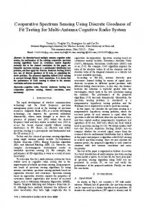
ening. Therefore MSE reduction can be theoretically achieved is above , thus needs as long as the value of to satisfy: (8) According to (5) and Fig. 1, it can be seen that the value of also decreases monotonously with increasing, which means the cross-correlation based positioning algorithm is more robust to noises for the interference signal with larger . , as Then it can be seen that (8) provides a valid region for illustrated in Fig. 3, within which the effect of increment on position MSE is more dominant than that of SNR reduction. It is worth noting that the curve in Fig. 3 only reflects the and variation trend and the relative relation between , thus when Hz, and from one starts to be smaller than . The exact curve point and (and thus the valid region for of ) is related with the actual shape of the power spectrum of vibration signal which cannot be numerical simulated, therefore quantitative analysis will be provided in Section III based on field test results. In practice, the property of signal power increment spectrum will influence the achievable range of as well as the variation slope of and with respect to , the theoretical relation of (8) provides a loose bound of . the valid region for III. FIELD TEST RESULTS AND DISCUSSION The setup we used in field test is shown in Fig. 4(a), which is the dual Mach-Zehnder interferometer configuration. The output of a distributed feedback (DFB) laser working at wavelength 1550 nm with 10 MHz linewidth (corresponding to
Fig. 5. Time domain waveforms of two channel original interference outputs.
30 m coherence length) and 5 mW power was split equally by a 3 dB coupler (coupler1) and then injected into the fiber Mach-Zehnder interferometer formed by coupler2 and coupler3 (both 3 dB couplers) from two sides. The lightwave then propagated oppositely in clockwise and counterclockwise directions respectively and interferenced at peer couplers. Two channel interference signals were detected by the photo-detectors PD1 and PD2 (with 2 GHz bandwidth) respectively and were sampled by a data acquisition (DAQ) card. The data was then processed at the industrial personal computer (IPC). A dynamic polarization controller (PC) was used to in-situ compensate the fix bias of polarization phase noise induced by polarization fading effect. Field test was proposed on an installed submarine cable between two islands of Zhejiang Province, China. Four idle fibers of the cable were used to form the sensor shown in Fig. 4(a). The length of the cable was 3000 m, and the vibration event was simulated by a diver footing on the cable at about 300 m from front side. All optical and electronic devices at both front and end sides were packaged in two stainless boxes for stability consideration. The data was collected at 1 MHz sampling freMHz). The original two channel interference quency ( signals are plotted in Fig. 5. The relatively high frequency oscillation region marked by two dashed black curves is caused by the vibration event. The inset of Fig. 5 shows the zoom-in figure
XIE et al.: POSITIONING ERROR REDUCTION TECHNIQUE
3523
Fig. 6. Power spectrum of (a) original and (b) filtered signal by HPF with 800 Hz cutoff frequency.
of the vibration part. It can be seen that due to the low resonance frequency of submarine cable, the vibration only lasts for about s). The low frequency drift of the signal is 0.05 s ( caused by the friction between cable and waves. The power spectrum of original interference signal is shown in Fig. 6(a). The central frequency and 3 dB bandwidth are around 120 Hz and 140 Hz respectively. In this situation, the product can be estimated as 7, which is much smaller than the requirement of 100 for accurate positioning. While it is worth noting that in original power spectrum there exists high-freHz) far from the lowquency components (e.g., frequency mainlobe, even if their magnitudes are about 30 dB lower than that of the mainlobe. Those ingredients are induced by the sudden change at the beginning of vibration as well as the harmonic components of the mainlobe. The signal processing procedure for the two channel interference signals is shown in Fig. 4(b). A 3-order Butterworth HPF was imposed on the original signal before cross-correlation positioning algorithm to achieve spectrum reshaping, as this type of filter is maximally flat in the passband and has a proper roll-off rate of 60 dB/decade. In order to determine the valid region as well as the optimal was varied from 100 Hz to 1500 Hz in step value of was estimated by of 100 Hz and the MSE value for each using 2000 trials with pseudo-random noise sequences [10]. is shown The obtained result of positioning MSE versus Hz represents direct cross-corin Fig. 7(a). The case of relation without using HPF. As a comparison, the curves of and versus are plotted in Fig. 7(b) and (c) respectively. The value of was estimated using (4). It can varies from 100 Hz to 300 Hz, the obbe seen that when tained MSE is larger than that of direct cross-correlation. This reduction (about 10 dB) is caused by the relatively large and small increment of (about 10 Hz) in this regime. The reduction is mainly due to the large slope of SNR rapid reduction when correlation coefficient is around unity acis so close to , the mainlobe cording to (4). And because
Fig. 7. (a) Positioning MSE (b)
(c) 3 dB bandwidth vs. cutoff frequency.
of original signal is not sufficiently attenuated which causes the is larger than 400 Hz, from small increment of . When where starts to significantly increase, the value of MSE becomes smaller than that of direct cross-correlation. The optimal occurs at 800 Hz with the minimum MSE of 10.1 dB, is from 400 Hz to 800 Hz within and the valid region for which positioning MSE is decreasing as well as is lower than that of direct cross-correlation. The reshaped power spectrum Hz case is shown in Fig. 6(b). By comparing it at with Fig. 6(a), it can be clearly seen that the 3 dB bandwidth is broadened due to the large attenuation of mainlobe. According Hz case the value to Fig. 7, it can be seen that for of bandwidth broadening and SNR reduction is 560 Hz and 16.7 dB respectively, the corresponding positioning MSE reduction is 2.53 dB, which agrees excellently with the theoretical prediction from (1) (which is 2.58 dB). While keep increasing , the gap of signal power spectrum at about 1100 Hz (see which saturates Fig. 6(b)) limits the further increasing of the effect of spectrum reshaping as shown in Fig. 7(c). Therefore from 900 Hz the contribution of SNR reduction dominates that the process and MSE starts to increase. The value of occurs at about 3 kHz (see the inset makes of Fig. 7(a)) with the value of about dB, which agrees well with the theoretical prediction from (5) (which is dB). Based on the above analysis, it can be seen that in and of the HPF is dethis case the valid region for termined by the property of signal power spectrum rather than . The same type of vibration event was repeated for another five times to test the repeatability of the technique. The diver
3524
JOURNAL OF LIGHTWAVE TECHNOLOGY, VOL. 30, NO. 22, NOVEMBER 15, 2012
ACKNOWLEDGMENT The authors would thank Ningbo Nuoke Electronic Technology Development CO., LTD, Zhejiang, China, for the help on field test. REFERENCES
Fig. 8. Positioning MSE vs. cutoff frequency of the five datesets for repeatability test.
TABLE I OPTIMAL CUTOFF FREQUENCIES AND CORRESPONDING POSITIONING MSE REDUCTION VALUES OF THE FIVE DATESETS FOR REPEATABILITY TEST
repeated the footing action with approximately the same force and speed, and the collected data were processed with the same procedure as that in Fig. 4(b). The obtained results of posifor the five datesets are plotted in tioning MSE versus Fig. 8. The optimal cutoff frequency and the corresponding positioning MSE reduction values are summarized in Table I. It can be seen that for all datasets positioning MSE varies with with the same trend, and all s are within the range of 500 Hz to 800 Hz. A maximum of 7 dB positioning MSE reduction is achieved (dataset No. 1) for this event by using the technique. The well repeatability of the technique also indicates can be used as the empirical parameter (e.g., that a fixed 600 Hz) for the specific type of event in practice. IV. CONCLUSION A novel positioning error reduction technique is proposed for distributed fiber interferometric vibration sensor by using signal power spectrum reshaping. A Butterworth HPF is used to broaden the 3 dB bandwidth of signal power spectrum by enhancing the weight of high-frequency components as well as attenuating the magnitude of low-frequency mainlobe. The interference signals with broadened 3 dB bandwidth can provide smaller positioning MSE. Both theoretical analysis and field test results show that there exists a valid region for the cutoff frequency of HPF within which the contribution of bandwidth broadening is more dominant than that of SNR reduction. In practice, this valid region for cutoff frequency is determined by the actual property of signal power spectrum. Field test results show that a maximum of 7 dB reduction of positioning MSE can be achieved when using the optimal cutoff frequency of HPF.
[1] A. J. Rogers, “Polarization-optical time domain reflectometry: A technique for the measurement of field distributions,” Appl. Opt., vol. 20, no. 6, pp. 1060–1074, 1981. [2] Z. Zhang and X. Bao, “Distributed optical fiber vibration sensor based on spectrum analysis of polarization-otdr system,” Opt. Exp., vol. 16, no. 14, pp. 10240–10247, 2008. [3] L. Palmieri, T. Geisler, and A. Galtarossa, “Limits of applicability of polarization sensitive reflectometry,” Opt. Exp., vol. 19, no. 11, pp. 10874–10879, 2011. [4] Y. Lu, T. Zhu, L. Chen, and X. Bao, “Distributed vibration sensor based on coherent detection of phase-otdr,” J. Light. Technol., vol. 28, no. 22, pp. 3243–3249, 2010. [5] Z. Qin, T. Zhu, L. Chen, and X. Bao, “High sensitivity distributed vibration sensor based on polarization-maintaining configurations of phase-otdr,” IEEE Photon. Technol. Lett., vol. 23, no. 15, pp. 1091–1093, 2011. [6] Y. Koyamada and H. Nakamoto, “High performance single mode OTDR using coherent detection and fiber amplifiers,” Electron. Lett., vol. 26, no. 9, pp. 573–574, 1990. [7] Y. Zhou, S. Jin, and Z. Qu, “Study on the distributed optical fiber sensing technology for pipeline leakage protection,” in Proc. SPIE, 2006, vol. 6344, p. 634435. [8] J. S. Patel, Z. Zhuang, and Y. Zadorozhny, “Phase Responsive Optical Fiber Sensor,” U.S. Patent WO2006/001868A2, 2005. [9] Q. Sun, D. Liu, J. Wang, and H. Liu, “Distributed fiber-optic vibration sensor using a ring Mach-Zehnder interferometer,” Opt. Commun., vol. 281, no. 6, pp. 1538–1544, 2007. [10] S. Xie, Q. Zou, L. Wang, M. Zhang, Y. Li, and Y. Liao, “Positioning error prediction theory for dual Mach-Zehnder interferometric vibration sensor,” J. Light. Technol., vol. 29, no. 3, pp. 362–368, 2011. [11] X. Hong, J. Wu, C. Zuo, F. Liu, H. Guo, and K. Xu, “Dual Michelson interferometers for distributed vibration detection,” Appl. Opt., vol. 50, no. 22, pp. 4333–4338, 2011. [12] C. Knapp and G. Carter, “The generalized correlation method for estimation of time delay,” IEEE Trans. Acoust., Speech, Signal Process., vol. 24, no. 4, pp. 320–327, 1976. [13] Y. Liu, L. Wang, C. Tian, M. Zhang, and Y. Liao, “Analysis and optimization of the pgc method in all digital demodulation systems,” J. Light. Technol., vol. 26, no. 18, pp. 3225–3233, 2008. [14] A. D. Kersey, M. J. Marrone, and A. Dandridge, “Observation of input-polarization-induced phase noise in interferometric fiber-optic sensors,” Opt. Lett., vol. 13, no. 10, pp. 847–849, 1988. [15] A. Galtarossa, L. Palmieri, M. Schiano, and T. Tambosso, “Statistical characterization of fiber random birefringence,” Opt. Lett., vol. 25, no. 18, pp. 1322–1324, 2000. [16] E. Weinstein and A. Weiss, “Fundamental limitations in passive timedelay estimation—Part II: Wide-band systems,” IEEE Trans. Acoust., Speech, Signal Process., vol. 32, no. 5, pp. 1064–1078, 1984. [17] J. Ianniello, “Time delay estimation via cross-correlation in the presence of large estimation errors,” IEEE Trans. Acoust., Speech, Signal Process., vol. 30, no. 6, pp. 998–1003, 1982.
Shangran Xie received the B.Sc. and M.Sc. degrees in electronic engineering from Tsinghua University, Beijing, China, in 2007 and 2009, respectively, where he is currently pursuing the Ph.D. degree in the Department of Electronic Engineering . He is a visiting student at Department of Physics, University of Ottawa, Canada, from September 2010 to December 2011. His research interest includes nonlinear fiber optics and distributed fiber sensing.