Proceedings of IPAC’10, Kyoto, Japan
THPEC023
POSITRON SOURCE SIMULATIONS USING GEANT4 A. Ushakov∗ , S. Riemann, A. Sch¨alicke DESY, Zeuthen, Germany Abstract The development of intense polarized positron sources for future linear colliders is a challenge. For the optimization of the positron source design a novel simulation tool, PPS-Sim [1] based on Geant4 [2] has been developed. PPSSim allows to determine polarization, beam properties, as well as energy deposition in accelerator components. All source components and their parameters can be chosen easily and flexible. Helical undulator, laser-Compton and coherent Bremsstrahlung in crystals are available as positron production schemes. Target materials and geometry can be adjusted. Flux concentrator, quarter wave transformer and lithium lens are implemented as possible capture devices. Geometry, accelerating components and magnetic field configuration can be specified by the user. In this contribution, PPS-Sim is presented, and selected results are discussed.
INTRODUCTION The development of an intense positron source for a future electron-positron collider (ILC, CLIC) or SuperB factory requires detailed design studies. For instance, the positron source for the ILC should deliver 3·1010 positrons in each of the 2625 bunches per pulse. To generate such an amount of positrons, it is planed to use a photon beam with an average power of more than hundred kilowatt. The problem of energy deposition in a relatively small volume of the conversion target, development of shock-waves and radiation damage of the target have to be studied carefully in order to ensure a reliable lifetime of the target. The efficiency of beam generation as well as the beam optics downstream the target play a crucial role for the design of the positron source components. Several Monte-Carlo tools are currently in use to simulate the positron production, as for example, EGS [3] and FLUKA [4]. But these tools do not include the particle transport in accelerating electrical fields. On the other hand, there are numerous well developed codes for simulations of beam transport and acceleration in linear and circular accelerators (MAD-X [5], Bmad [6], Elegant [7], etc.). Some codes facilitate the transport of low-energetic beams including space charge effects (ASTRA [8], BEAMPATH [9]), or spin transport (Bmad, BEAMPATH). But all of these codes do not describe the process of positron production and need the input from EGS, FLUKA or other codes. A Geant4-based toolkit can combine beam generation, beam focusing, and acceleration. Geant4 [2] includes
positron production, energy deposition, and also transport of charged particles in magnetic and electric fields, and spin transport. The idea to use the Geant4 framework for accelerator-related issues is not new. G4beamline [10] and bdsim [11] can be used for beamline simulations. In this contribution, the Geant4-based application developed for Polarized Positron Source Simulation (PPS-Sim), is described.
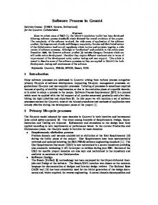
DESCRIPTION OF CODE Dependencies and Capacities PPS-Sim is based on the Geant4, ROOT and Qt4 libraries. Geant4 is used to simulate the electro-magnetic shower in the target, the polarization transfer, and the particle and spin tracking in electro-magnetic fields. Geant4 has a powerful geometry package and different possibilities to visualize the geometry of the model, particle trajectories and energy deposition in positron source components. ROOT is used for fast “on-line” analysis of simulation results, importing input data and saving results. The Graphical User Interface (GUI) is based on Geant4 and Qt4 libraries. The main positron source parts included in PPS-Sim are schematically shown in Fig. 1. The main source elements are the primary beam, the conversion target, the magnetic focusing system called Optical Matching Device (OMD) and the accelerator cavity (RF). Primary Beam
Target
OMD
RF
e+
Figure 1: Schematic diagram of main source parts included in PPS-Sim.
Different options for the source design are implemented in PPS-Sim. The primary beam can be chosen between a photon beam generated in an undulator (undulator-based source), an electron beam (conventional source) or using a data file, for example, with a Compton photon spectrum (Compton source) or channeling radiation spectrum (source with mono-crystal and amorphous target). PPS-Sim generates the energy spectrum, spatial distribution and polarization of the undulator photons automatically after selecting the energy of the drive electron beam, the undulator K-value, the undulator period λ, and the distance between undulator and target. For the generation of undulator photons the Kincaid’s equations [12] are numerically integrated. The typical undulator spectrum (number ∗
[email protected] photons generated by one electron passing one meter of 03 Linear Colliders, Lepton Accelerators and New Acceleration Techniques T02 Lepton Sources
4095
THPEC023
Proceedings of IPAC’10, Kyoto, Japan
undulator) and the polarization of the primary photons are shown in Fig. 2 for the ILC positron source.
The frequency, amplitude and phase of E-field can be adjusted. All parameters necessary to describe the fields, dimensions and the relative positions of the source parts can be configured via macro-files or interactively in a GUI session or using the command line. PPS-Sim does not include the whole beam line up to the damping ring (DR) at 5 GeV. In order to estimate the number of positrons out off the DR acceptance, PPS-Sim applies cuts on the longitudinal bunch size and on the sum of x- and y-emittances (so-called diagonal emittance cut). By default PPS-Sim applies a ∼10 mm longitudinal cut that corresponds to a change of the electric field phase by about 15◦ .
Visualization, User Interface and Running Modes Figure 2: Energy spectrum and polarization of photons generated in a helical undulator by 150 GeV electrons. Undulator: K = 0.92, λ = 11.5 mm. Optionally, a photon collimator can be placed between undulator and target to enhance the polarization and to reduce the energy deposition in the target. But instead of including the “real” collimator as geometrical object, the photons outside the collimator radius are simply disregarded. Two kinds of conversion targets can be used: a solid wheel or a liquid (lead) target. The target material, thickness and other geometrical dimensions as well as the windows for liquid target can be chosen arbitrarily. Three options of OMD have been implemented: pulsed flux concentrator or adiabatic matching device (AMD), Lithium lens, and quarter-wave transformer (QWT). The AMD is a tapered solenoid with high field strength at the beginning and low field strength at the end. The field along the beam (and solenoid) axis B0 can be described as B0 (z) =
Bini , 1 + gz
where Bini is the initial field and g is the taper parameter. The magnetic field of the Lithium lens is simplified and described by analytical functions. Assuming that the current I in the lens has only one (z) component and an equal density everywhere inside the lens, it is in cylindrical coordinates Bz , Br = 0 and Bϑ (r) =
μ0 Ir , 2πa2
for r ≤ a,
The 3D source model with liquid target and QWT is shown in Fig. 3. The user friendly visualization (OpenGLbased) of the geometry and particle trajectories is very useful for model development and debugging.
Coils
Target Cavity
Figure 3: 3D view of the source model for liquid target with flow channel, windows and QWT (two coils). The electron trajectories are shown in red, positron trajectories in blue. Using the GUI allows to configure the properties of the source components, to visualize the geometry model, to perform simulations (optimizations), and to analyze results without any advanced knowledge of Geant4 or C++. In the interactive mode all Geant4 commands can be applied using the command line in the main window. For simulations that require huge statistics, PPS-Sim can be started in batch mode. The simulation results (positron coordinates, momenta, energy and polarization after the target and at the end of cavity) are saved in a ROOT file or optionally in text files.
where μ0 is the permeability of free space, and a the radius of the lens. A realistic implementation was studied in [13]. SELECTED RESULTS The QWT consists of two solenoids. The first one has a higher and the second a lower field. Currently PPS-Sim PPS-Sim has been developed for the optimization of the assumes that the field inside the solenoids is constant and source parameters. For example, Fig. 4 shows an example in the region between them decreasing linearly. of a Li-lens length scan for the ILC positron source. In this The E-field of the RF cavity is modeled as harmonic plot the positron yield, defined as number of “captured” function, embedded into a solenoid with constant B-field. positrons per one photon incident on the target, are plotted 03 Linear Colliders, Lepton Accelerators and New Acceleration Techniques 4096
T02 Lepton Sources
Proceedings of IPAC’10, Kyoto, Japan together with the positron polarization as function of the lens length. 10−3
45
5.0
40
MeV/cm 3 /e +
10
450
9
400
8
350
4.5
35
4.0
30
3.5
25 2
4
6
Llens
8
[mm]
10
12
Figure 4: Positron yield and polarization versus length of the Li-lens for an undulator-based source with 150 GeV drive electron beam, K = 0.92, λ = 11.5 mm, Ti-alloy target of 0.4 radiation length, and a Li-lens with 120 A current and 8.5 mm radius.
r [mm]
7
Polarization [%]
Yield [e+/ph]
x
THPEC023
300
6
250
5
200
4
150
3 2
100
1
50
0
2
4
6
8
10
12
14
z [mm] Figure 6: Spatial distribution of energy deposition in the target. Source parameters: 150 GeV drive beam, K = 0.92, λ = 11.5 mm, 4.6 mm collimator aperture, 0.4X0 Ti target.
SUMMARY In Fig. 5 the focusing power of the pulsed flux concentrator is shown. The normalized positron yield (per one electron passing 100 m undulator) calculated by PPS-Sim for the ILC source is plotted together with results from reference [14] obtained by combining EGS with Elegant.
Elegant PPS−Sim
Yield
[e+ /e
_
]
5
REFERENCES
4 3 2 1 0 0
PPS-Sim is a flexible Geant4-based tool for positron source simulation and optimization. It includes a variety of source options. The graphical user interface is easy to use and to extend. The visualization of the geometry is useful for development and debugging. PPS-Sim is an opensource code and available for download from [1].
2
4
6
Bini [T]
8
10
Figure 5: Normalized positron yield (per one electron passing 100 m undulator) depending on the initial magnetic field of AMD as obtained using EGS and Elegant (dashed line), and using PPS-Sim (solid line). Parameters of the source: 250 GeV drive beam, K = 0.92, λ = 11.5 mm, Ti target of 0.4 X0 , taper parameter g = 0.06 mm−1, solenoid B = 0.5 T.
[1] PPS-Sim web site, http://pps-sim.desy.de. [2] S. Agostinelli et al. (G EANT 4 Collaboration), Nucl. Instr. and Meth. A 506, 250 (2003); J. Allison et al., IEEE Trans. Nucl. Sci. 53, 270 (2006). [3] Electron Gamma Shower (EGS) web site, http://www2.slac.stanford.edu/VVC/egs/. [4] A. Ferrari, P.R. Sala, A. Fass`o, and J. Ranft, “FLUKA: a multi-particle transport code”, CERN 2005-10 (2005), INFN/TC 05/11, SLAC-R-773. [5] MAD-X web site, http://mad.web.cern.ch/mad/. [6] Bmad web site, http://www.lns.cornell.edu/∼dcs/bmad. [7] M. Borland, Advanced Photon Source LS-287, September 2000. [8] K. Fl¨ottmann, “ASTRA. A Space Charge Tracking Algorithm”, http://wwww.desy.de/∼mpyflo/. [9] Y.K. Batygin, Nucl. Instrum. Meth. A 539 (2005) 455. [10] Muons, Inc.: G4beamline, http://g4beamline.muonsinc.com. [11] bdsim web site, http://www.pp.rhul.ac.uk/twiki/bin/view/JAI/BdSim. [12] B.M. Kincaid, J. Appl. Phys. 48 (1977) 2684. [13] A. Mikhailichenko, Cornell University Report (2010) CBN 10-3. [14] W. Gai, (ANL), 2009, private communication.
For the Peak Energy Deposition Density (PEDD) analysis a special running mode is provided. A typical example of the energy deposition inside the titanium-alloy target is shown in Fig. 6 for the undulator-based source including a photon collimator. 03 Linear Colliders, Lepton Accelerators and New Acceleration Techniques T02 Lepton Sources
4097