1464
IEEE TRANSACTIONS ON POWER DELIVERY, VOL. 23, NO. 3, JULY 2008
Possibility of Power Tapping From Composite AC–DC Power Transmission Lines H. Rahman and B. H. Khan, Senior Member, IEEE
Abstract—A recently proposed concept of simultaneous ac–dc power transmission enables the long extra high-voltage ac lines to be loaded close to their thermal limits. The conductors are allowed to carry a certain amount of dc current superimposed on usual ac. This paper presents the feasibility of small power tapping from composite ac–dc power transmission lines which would pass over relatively small communities/rural areas having no access to a major power transmission network. The proposed scheme is digitally simulated with the help of a PSCAD/EMTDC software package. Simulation results clearly indicate that the tapping of a small amount of ac power from the composite ac–dc transmission line has a negligible impact on the normal functioning of the composite ac–dc power transmission system. Index Terms—PSCAD simulation, simultaneous ac–dc power transmission, small power tapping.
I. INTRODUCTION
P
RESENTLY, about half of the world’s population, especially those in developing countries, live without electricity [1]. These days, the supply of electricity is considered essential to avail normal facilities of daily life. Its availability is fundamental for economic development and social upliftment. Large power (steam, hydro, nuclear) stations are usually located far from load centers. The wheeling of this available electric energy from these remotely located stations to load centers is achieved either with extra high-voltage (EHV) ac or HVDC transmission lines. These EHV ac /HVDC transmission lines often pass over relatively small communities/rural areas that do not have access to a major power transmission network. It is most desirable to find methods for connecting these communities to the main transmission system to supply cheap and abundant electrical energy. However, the HVDC transmission system does suffer a significant disadvantage compared to EHV ac transmission, in regards to the tapping of power from a transmission system. Techno-economical reasons prevent the tapping of a small amount of power from HVDC transmission lines. This is considered a major drawback due to the fact that in many instances, HVDC transmission lines pass over many rural communities that have little or no access to electricity. In the past, a number of schemes have been proposed for small power tapping from HVDC lines. Most of these schemes
Manuscript received January 5, 2007; revised March 26, 2007. Paper no. TPWRD-00005-2007. The authors are with the University Polytechnic, Aligarh Muslim University, Aligarh 202 002, India (e-mail:
[email protected]). Color versions of one or more of the figures in this paper are available online at http://ieeexplore.ieee.org. Digital Object Identifier 10.1109/TPWRD.2008.916760
use forced commutated or line commutated inverters to tap off the power from the HVDC system. These schemes inherently required additional commutation circuitry or local generation which, in turn, leads to the high cost of installations and operational complications [3]–[5]. Ekstrom and Lamell [3] have proposed a scheme for small power tapping from an HVDC line based on a current source line-commutated single-phase thyristor bridge, connected in series with the HVDC line. To start the tap operation, a local dc voltage source is required in this scheme. The available bulk electric energy can also be wheeled by simultaneous ac-dc power transmission recently proposed by the authors [2]. In this scheme, the conductors are allowed to carry superimposed dc current along with ac current. The feasibility of simultaneous ac-dc power transmission has been proved by laboratory modeled experimental verification as well as digital simulation. Substantial power upgrading has already been demonstrated by converting the EHV ac line into a composite ac-dc transmission line without any alteration. The transmission angle can be increased up to 80 in a composite ac-dc line without losing transient stability, which is impossible in a pure EHV ac line. From this composite ac–dc line, small power tapping is also possible despite the presence of a dc component in it. This paper proposes a simple scheme of small power tapping from the composite ac–dc power transmission line along its route. In this study, the tapping stations are assumed to draw power up to 10% of the total power transfer capability of the composite line. However, more power tapping is also possible subject to the condition that it is always less than the ac power component. II. SMALL POWER TAPPING STATION REQUIREMENTS The main requirements of a small power tapping stations are as follows. • The per unit cost of the tap must be strongly constrained (i.e., the fixed cost must be kept as low as possible). • The tap must have a negligible impact on the reliability of the ac–dc system. This implies that any fault in the tap must not be able to shutdown the whole system. • The tap controls should not interfere with the main system (i.e., the tap control system has to be strictly local). Failure to achieve this leads to a complex control system requirement and, thus, higher cost of hardware. • Small tap stations having a total rating less than 10% of the main terminal rating have potential applications where small, remote communities or industries require economic electric power [1]–[4]. The tapping stations considered in this study are of fairly small power rating, up to 10% of the total transfer capacity of
0885-8977/$25.00 © 2008 IEEE
RAHMAN AND KHAN: POSSIBILITY OF POWER TAPPING
1465
(a)
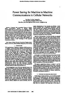
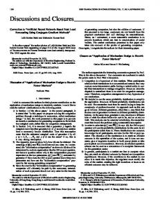
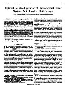
(b) Fig. 1. Single-line diagram of (a) basic composite ac-dc transmission system and (b) power tap substation.
the composite ac-dc power transmission line. Short interruption of the power supplies should be tolerable at the occurrence of temporary earth faults on the main simultaneous ac–dc power transmission system. Further, any fault occurring within tapping station and its local ac network is to be cleared by local CBs. These tapping stations will not depend upon the telecommunication links with the main composite ac–dc transmission system. III. SYSTEM UNDER STUDY The network depicted in Fig. 1(a) has been taken up for the feasibility of a small power tap for remote communities from the composite ac–dc power transmission system. The details of power tap substations are shown in Fig. 1(b). The modeling details of the network components are described in [2]. A synchronous machine is delivering power to an infinite bus via a double-circuit three-phase, 400-kV, 50-Hz, 450-km ac transmission line. The minimum value of ac phase voltage and maximum value of dc voltage with respect to ground of the converted composite ac–dc line, respectively,
times that of per phase voltage before are 1/2 and conversion of the conventional pure EHV ac line [2]. The line considered is converted to a composite ac–dc transmission line with an ac rated voltage of 220 kV and a dc voltage of 320 kV. In a composite ac–dc transmission line, the dc component is obtained by converting a part of the ac through a line-commutated 12-pulse rectifier bridge similar to that used in a conventional HVDC. The dc current thus obtained is injected into the neutral point of the zig-zag-connected secondary windings of sending end transformer. The injected current is distributed equally among the three windings of the transformer. The same is reconverted to ac by the conventional line commutated inverter at the receiving end. The inverter bridge is connected to the neutral of zig-zag-connected winding of the receiving end transformer. The transmission line is connected between the terminals of the zig-zag windings at both ends. The double-circuit transmission line carries both three-phase ac as well as dc power after conversion to a composite ac–dc line. The zig-zag connection of secondary windings of the transformer is used at both ends to avoid
1466
IEEE TRANSACTIONS ON POWER DELIVERY, VOL. 23, NO. 3, JULY 2008
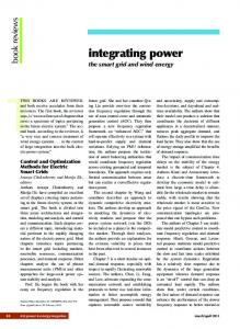
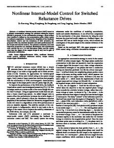
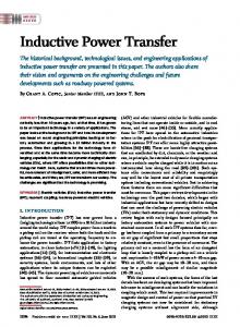
Fig. 2. (a) Line-to-ground (phase) voltage of the composite ac–dc line. (b) Three-phase line-to-line voltages in the composite ac–dc line at the tapping point of the substation input. (c) Phase A conductor current in the composite ac–dc line. (d) Phase A current at the input of the tap substation at a particular load. (e) Tap substation phase voltage on the local load side.
saturation of the core due to the flow of the dc component of current. The replacement of a Y-connected transformer from a conventional EHV ac line with a zig-zag transformer in composite ac–dc power transmission is accomplished along with the reduction of ac voltage in such a way that the insulation-level requirements remain unaltered. However, the neutral point of this transformer needs insulation to withstand the dc voltage. Moreover, the zig-zag transformer transfers only 25% of the total power by transformer action. Fig. 2(a) shows the line-to-ground voltage (i.e., phase voltage) characteristic of the composite ac–dc line which is offset from zero as it possesses a dc voltage component superimposed on a sinusoidally varying ac voltage component. Since the line-to-line voltage does not carry any dc component,
it has a pure ac waveshape as demonstrated in Fig. 2(b). The composite-line conductor current characteristic illustrated in Fig. 2(c) indicates the presence of a dc component injected along with an ac component whereas Fig. 2(d) shows the current characteristic at the input of the tap substation. The voltage and current waveforms at the tap substations as depicted in Fig. 2(b), (d), and (e), indicate neither the presence of the dc component nor distortion in waveforms though these are derived from the composite line. To tap ac power from the line, the transformer can be directly connected to the conductors of the line without breaking them. In this study of a composite ac-dc transmission line, the ac-line voltage component has been selected as 220 kV. Each tapping station transformer (rated as 120 MVA, 220/66 kV,
RAHMAN AND KHAN: POSSIBILITY OF POWER TAPPING
1467
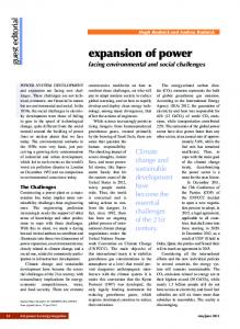
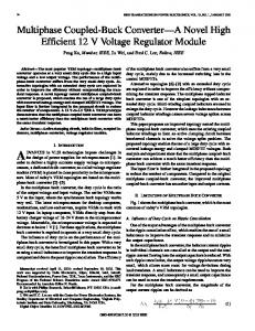
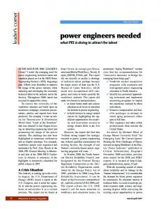
Fig. 3. (a) Transformer primary line currents. (b) Tap power (Pt1), receiving end (Pac) ac power, sending end (Pacs) ac power, and receiving end dc power (Pinvdc). (c) AC (Pac), dc (Pinvdc), and total (P_tranfer) power transfer at the receiving end. (d) Qrecdc and Qinvdc reactive power drawn by the rectifier and inverter. Qac-send and Qac-Rend reactive power drawn by the lines from each end. (e) Rectifier (Vdr) and inverter (Vdi) dc voltages. (f) Transmission angle (Transm_Angle).
) is connected to the local ac load via a circuit breaker (CB) as depicted in Fig. 1(b). These CBs are provided for local protection, to clear the fault within the local ac network. The nature of the local load considered here is that of a summertime residential class with the following characteristics [6], [7]: ; ; voltage index for power ; voltage index for Q frequency index for power ; . frequency index for Q IV. DIGITAL SIMULATION OF THE PROPOSED SCHEME In order to examine the feasibility of the proposed scheme for power tapping and to observe the performance of the composite
ac-dc power transmission system under various operating conditions, the digital simulation software package PSCAD/EMTDC was used. The initial operating conditions of the simultaneous ac–dc power transmission system before the tapping power is switched on are the following: ; ac power at the receiving end ; dc power at the receiving end total power transfer at the receiving end ; . transmission angle A. Case A: Equal Power Tapping From Each Line of the Double-Circuit Line at Different Instants The system is initially considered to be delivering the scheduled real power to an infinite bus. At time 0.5 s, a load of 50
1468
IEEE TRANSACTIONS ON POWER DELIVERY, VOL. 23, NO. 3, JULY 2008
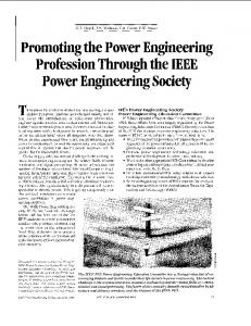
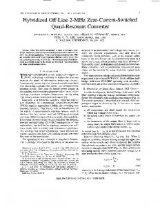
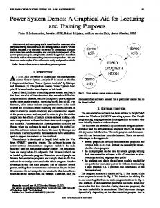
Fig. 4 (a) Tap power (Pt1), receiving end (Pac) ac powers, sending end (Pacs) ac power, and receiving end dc power (Pinvdc). (b) AC (Pac), dc (Pinvdc), and total (P_tranfer) power transfer at the receiving end. (c) Qrecdc, Qinvdc reactive power drawn by the rectifier and inverter. Qac-send and Qac-Rend reactive power drawn by the line from each end. (d) Rectifier (Vdr) and inverter (Vdi) dc voltages.
MW is switched on by closing the CB of one tapping station transformer which is directly connected to one of the doublecircuit lines located in the midway (i.e., at 225 km from the sending end). Subsequently, at time 4.5 s, another load of 50 MW is switched on by closing the CB of the second tapping station transformer which is connected directly to the second line. The transient responses for these conditions are shown in Fig. 3(a)–(f). Fig. 3(a) shows the line current waveforms entering into the primary of the tapping transformer. These current (at a particular load) waveforms do not exhibit any dc offset though these are drawn directly from the composite ac–dc line. Fig. 3(b) shows the time-based responses of real power delivery by the system to the tapping station and to the receiving end. It can be seen that whenever the tap station is switched on, it draws ac power from the system. The receiving end ac power is reduced by the same amount. The total power delivery by the line at the receiving end is also reduced by the same amount due to the diversion of a part of ac power to the tapping substations. This is illustrated in Fig. 3(c). The time-based responses of reactive power, drawn by the converters and lines, are shown in Fig. 3(d). It indicates that the lines draw additional reactive power from the sending end to meet the tap station reactive power requirement as the tap is switched ON. The capacitive shunt compensation at the tap substation input may be used to improve the voltage profile of the ac component of the composite ac dc line as well as to meet the reactive power requirement locally. This fact has been confirmed through simulation studies. Moreover, these results are not included here.
The aforementioned time-based simulated responses of the rectifier and inverter dc voltages and transmission angle between two ends of the line do not deteriorate during steady state. It has also been seen that the sending and receiving-end bus voltages, generator active and reactive powers, generator speed deviation, and rectifier and inverter firing angles remain constant. However, there is a very small effect during the transient period after switching ON tapping. Case B. Unequal Power Tapping From Each Double-Circuit Line at Different Instants: The system is initially assumed to be operating at same conditions as mentioned in case A, delivering the scheduled real power to an infinite bus. At time 0.5 s, a load of 100 MW was switched on by closing the CB of one tapping station transformer which is directly connected to one of the double-circuit lines located midway (i.e., at 225 km from the sending end). Subsequently, at time, 3.5 s, another load of 50 MW was switched on by closing the CB of the second tapping station transformer connected to the second line. The transient responses for these conditions are shown in Fig. 4(a)–(d). The aforementioned time-based simulated responses of various system parameters do not show any deterioration of the performance of the ac–dc composite system except a negligible effect during the transient period at the time of switching on tap substations. Case C. Tapping Power Station Fault Responses: 1) Three-Phase-to-Earth (ABC-G) Fault between Tap Transformer and Load: Initially, the simultaneous ac–dc system with small power tap is assumed to be operating in its steady state with the following conditions:
RAHMAN AND KHAN: POSSIBILITY OF POWER TAPPING
1469
Fig. 5. (a) Tap power (Pt1), receiving end (Pac) ac power, sending end (Pacs) ac power, and receiving end dc power (Pinvdc). (b) Line voltage variations across the CB’s input. (c) Transformer input line currents variations measured at the CB’s input. (d) Transmission angle (Transm_Angle). (e) Sending (Vs_rms) and receiving (Vr_rms) end bus voltages. (f) Rectifier (AOR) and inverter (Aoi) firing angle order. (g) Rectifier (Vdr) and inverter (Vdi) dc voltages. (h) Generator’s speed deviation (delta omega). (i) Generator’s active (Pg) and reactive (Qg) power output.
1470
IEEE TRANSACTIONS ON POWER DELIVERY, VOL. 23, NO. 3, JULY 2008
Fig. 6. (a) Tap power (Pt1), receiving end (Pac) ac power, sending end (Pacs) ac power, and receiving end dc power (Pinvdc). (b) Line voltage variations across the CB’s input. (c) Transformer input line currents variations measured at the CB’s input. (d) Sending (Vs_rms) and receiving-end (Vr_rms) bus voltages. (e) Rectifier (AOR) and inverter (Aoi) firing-angle order. (f) Rectifier (Vdr) and inverter (Vdi) dc voltages. (g) Generator’s speed deviation (delta omega). (h) Generator’s active (Pg) and reactive (Qg) power output.
equal power tap on each line, midway at the line ; receiving-end ac power MW; MW; sending-end ac power MW; DC power at the receiving end . transmission angle
s, a solid three-phase-to-ground fault occurs At time between the tap transformer and the local load. After a period of three cycles (60 ms), the trip signal is given to the local circuit breaker (CB) to clear the fault. Thereafter, CBs are reclosed after a delay of three cycles (60 ms) from the instant of clearing fault. Fig. 5(a)–(i) shows the transient responses for this fault condition.
RAHMAN AND KHAN: POSSIBILITY OF POWER TAPPING
2) Single-Phase-to-Earth (A–G) Fault Between the Tap Transformer and Load: Now considering similar initial conditions as mentioned in case (i), except that now the type of fault is a solid single-phase to ground instead of a three-phase-to-ground fault, with the same sequence of events. Various transient responses for this fault condition are shown in Fig. 6(a)–(h). Fig. 5(a)–(i) and Fig. 6(a)–(h) are the responses after the occurrence of faults in a local ac network of small tapped power for rural communities from the composite ac–dc transmission system. These local faults cause minor disturbance for a short transient period only. V. CONCLUSION The feasibility of tapping a small amount of power to feed remotely located communities in the same simple way as tapping in the case of an EHV ac line is demonstrated for the composite ac–dc transmission system. It is also economical compared to complicated methods of tapping from the HVDC line. The results clearly demonstrate that the tapping of a small amount of ac component of power from the composite ac–dc transmission line has a negligible impact on the dc power transfer. REFERENCES [1] L. Chetty, N. M. Ijumba, and A. C. Britten, “Parallel-cascaded tapping station,” in Proc. IEEE Int. Conf. Power System Technology, 2004, pp. 1674–1878. [2] H. Rahman and B. H. Khan, “Power upgrading of transmission line by combining ac-dc transmission,” IEEE Trans. Power Syst., vol. 22, no. 1, pp. 459–466, Feb. 2007. [3] A. Ekstrom and P. Lamell, “HVDC tapping station: Power tapping from a dc transmission line to a local ac network,” in Proc. AC-DC Conf., London, U.K., 1991, pp. 126–131.
1471
[4] Task force on Small HVDC Taps, Working Group, “Integration of small taps into (existing) HVDC links,” IEEE Trans. Power Del., vol. 10, no. 3, pp. 1699–1706, Jul. 1995. [5] M. R. Aghaebrahimi and R. W. Menzies, “Small power tapping from HVDC transmission system: A novel approach,” IEEE Trans. Power Del., vol. 12, no. 4, pp. 1698–1703, Oct. 1997. [6] PSCAD/EMTDC, User’s Guide Manitoba-HVDC Research Centre. Winnipeg, MB, Canada, Jan. 2003. [7] P. S. Kundur, Power System Stability and Control. New York: McGraw-Hill, 1994. H. Rahman received the B.Sc. (Engg.), M.Sc. (Engg.), and Ph.D. degrees in electrical engineering, from Aligarh Muslim University (AMU), Aligarh, India. He was an Electrical Engineer in India and abroad from 1980 to 1985. Since 1985, he has been on the faculty of the University Polytechnic, AMU, where he is currently a Reader in the Electrical Engineering Department. He has published several research papers in international journals and conferences. He was also engaged in a research project on “AC-DC Power Transmission” sponsored by AICTE, New Delhi. His research interests include HVDC and FACTS.
B. H. Khan (SM’02) received the B.Sc.(Engg.) degree from Aligarh Muslim University (AMU) Aligarh, Aligarh, India, in 1976, the M.E. degree from Indian Institute of Science, Bangalore, in 1978, and the Ph.D. degree from the Indian Institute of Technology, Kanpur, in 1989. Since 1978, he has been on the faculty of the Electrical Engineering Department, AMU Aligrarh, where he is now a Professor. He has published many research papers in international/national journals and conferences. He has worked on several sponsored research projects. His current areas of interest include nonconventional and renewable energy sources, power electronics, and microprocessor applications. Dr. Khan is recipient of President of India Medal of IE (India) 2002 and Railway Board’s First Prize of 1986–1987. He is a Life Fellow of IE (India), Life Member of Indian Society for Technical Education, and Life Member of the System Society of India.