Department of Computer Science1 and Department of Electrical and ... environment to support modelling using the notation. ..... 23, no. 6, 347-365, June 1997.
Pounamu: a meta-tool for multi-view visual language environment construction Nianping Zhu1, John Grundy1, 2 and John Hosking1 Department of Computer Science1 and Department of Electrical and Computer Engineering2, University of Auckland, Private Bag 92019, Auckland, New Zealand {nianping | john-g | john}@cs.auckland.ac.nz Abstract We describe a meta tool for specification and generation of multiple view visual tools. The tool permits rapid specification of visual notational elements, underlying tool information model requirements, visual editors, the relationship between notational and model elements, and behavioural components. Tools are generated on the fly and can be used for modelling immediately. Changes to the meta tool specification are immediately reflected in any tool instances. The tool has been used to generate a wide range of visual environments, and is designed for ready extension and integration with other tools.
1. Introduction Multi-view, multi-notational visual environments are popular tools in a wide variety of domains. Examples include software design tools [16], circuit designers [27], visual programming languages [4], user interface design tools [25], and children’s programming environments [7]. In our own work we have developed a variety of such applications [1], [13]. Many frameworks, meta-tool environments and toolkits have been created to help support the development of such visual language environments. These include MetaEdit+ [18], MetaMOOSE [9], Escalante [23], PEDS [35] and DiaGen [24]. We have had a long term interest in developing frameworks and meta tools supporting development of such tools, including the MViews/JViews framework and JComposer/BuildByWire meta-tools [12], [14]. However, current approaches to developing multipleview visual language tools suffer from several deficiencies. Tools may be easy to learn and use but usually these provide support for only a limited range of target visual environments. Alternatively, the tools are very flexible but require considerable programming ability to develop even small environments, providing high barriers to use. In addition, most meta-tools have a standard edit-compile-run cycle, requiring complex tool regeneration each time a minor notation change is made. Our aim in this work was to produce a new meta-tool, Pounamu1, that could be used to rapidly design, prototype 1
Pounamu is the Maori word for greenstone jade, used by Maori to produce tools, such as adzes or knives, and objects of beauty, or taonga, such as jewellery.
and evolve tools supporting a very wide range of visual notations and environments, ameliorating these deficiencies. To achieve this we based Pounamu’s design on two overarching requirements: • Simplicity of use. It should be very easy to express the design of a visual notation, and generate an environment to support modelling using the notation. • Simplicity of extension and modification. It should be possible to rapidly evolve proof of concept tools by modification of the notation, addition of back end processing, integration with other tools, and behavioural extensions (eg complex constraints). In this paper we first survey related work. We then overview our Pounamu toolset and describe its visual tool specification and modelling support, illustrating with a simple UML-based diagram tool. We discuss Pounamu’s architectural support for tool evolution and briefly describe Pounamu’s design. A survey of applications we have developed to evaluate the utility of the tool is followed by a summary of the contributions of this research and overview of possible future work.
2. Related Work Three main approaches exist for the development of the types of visual, multiple view environments described in the previous section: the use of reusable class frameworks; meta-tools; and visual language toolkits. Frameworks provide low-level yet very powerful sets of reusable facilities for building specific kinds of visual language tools or quite general-purpose applications, depending on their degree of domain specialisation. General purpose frameworks include MVC [17], Unidraw [32], COAST [30], and HotDoc [3]. These typically lack abstractions specific to multi-view, visual language environments, so construction of tools is time-consuming. Special purpose frameworks include Meta-MOOSE [9], JViews [14], and Escalante [23]. These offer more easily reusable facilities for visual language environments, but require detailed programming knowledge and a compile/edit/run cycle, limiting their ease of use and flexibility for exploratory development. Many general-purpose toolkits that are suitable for visual language development have been produced, including Tcl/Tk [33], Suite [8], and Amulet [25]. These combine rapid applications development tools and programming extensions. As they lack high-level
abstractions for visual, multi-view environments, more targeted toolkits have been produced to make such development easier. These include Vampire [22], DiaGen [24], VisPro [34], JComposer [14] and PROGRES [28]. Some of these use a code generation approach from a specification model, e.g DiaGen and JComposer. Others, such as PROGRES and VisPro, are based on formalisms such as graph grammars and graph rewriting which are used for high-level syntactic and semantic specification for visual language tools. Code generation approaches suffer from similar problems to many toolkits: edit/ compile/run cycle needed and difficulty in integrating third party solutions. Formalism-based visual language toolkits may limit the range of visual languages supported and are often difficult to extend in non-planned ways e.g. adding code generation or collaborative editing facilities. Meta-tools provide an integrated environment for developing other tools. These include MetaEdit+ [18], MOOT [26], GME [21], MetaEnv [2] and IPSEN [19]. Usually they aim for a degree of round-trip engineering of the target tools. Typically meta-tools provide good support for their target domain environments. However they are often limited in their flexibility and degree of integration with other tools [12]. The majority of the above approaches require detailed programming and class framework knowledge or understanding of complex information models (eg graph grammars). Few of these environment development tools support round trip engineering and live, evolutionary development. Regeneration of code can be a large problem when integrating backend code.
library or to write and dynamically add new ones as Java plug-in components. Event handlers can be used to add: • view editing behaviour e.g. “if shape X is moved, move shape Y the same amount”; • view and model constraints e.g. “all instances of entity Z must have a unique Name property”; • user-defined events e.g. “check model is consistent when user clicks button”; • event-driven extensions e.g. “generate C# code from the design model instance information”; and • environment extension plug-ins e.g. “initialise the collaboration plug-in to support synchronous editing of a shared Pounamu diagram by multiple users”. Pounamu Meta-tool Application Specification Tools
Modelling Tools
Shape Designer
Modelling Views
Meta-model Designer Event handler Designer
Event Handlers
View Designer Model Entity instances Tool Specifcations – XML documents
Plug-ins
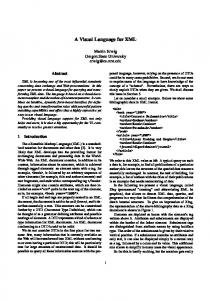
3. Overview of Our Approach Figure 1 shows the main components of the Pounamu meta-tool. A user of Pounamu initially specifies a metadescription of the desired tool. Specification tools allow definition of the appearance of visual language notation components (“Shape Designer”), views for graphical display and editing of information (“View Designer”), the tool’s underlying information model as meta-model types (“Meta-model Designer”), and event handlers to define behaviour semantics (“Event Handler Designer”). Tool projects are used to group individual tool specifications. Having specified a tool or obtained someone else’s tool project specification, users can create multiple project models associated with that tool. Modelling tools allow users to create modelling projects, modelling views and edit view shapes, updating model entities. To support ease of use, the shape, view and metamodel designers use high-level visual programming tools with relatively simple appearance and semantics. To provide flexibility, the event handler designer allows tool designers to choose predefined event handlers from a
Tool specification projects (XML)
Modelling projects (XML)
Web Services APIs
Figure 1. The Pounamu approach. Pounamu uses an XML representation of all tool specification and model data, which can be stored in files, a database or a remote version control tool. Pounamu provides a full web services-based API used to integrate the tool with other tools, or to remotely drive the tool.
4. Tool Specification using Pounamu Figure 2 (a) shows an example of the Pounamu shape designer in use. On the left a hierarchical view provides access to tool specification components and models instantiated for that tool. In the centre are visual editing windows for defining tool specification components and model instances. Here, a shape is defined representing a generic UML class icon. To the right is a property editing panel supplementing the visual editing window. General information is provided in a panel at the bottom.
Figure 2 (b) shows a UML class diagramming tool, the shape icon of which has been partially defined in Figure 2 (a), in use modelling a person class, with two subclasses student and staff. This shape specification could be reused for other modelling tools e.g. UML class diagrams.
connector shown in Figure 3. The tool permits specification of line format, end shapes, and labels or edit fields associated with the connector’s ends or centre.
Figure 3. Example of the Connector designer. The underlying tool information model is specified using the meta model designer, as in Figure 4. This uses an Extended Entity Relationship (EER) model as its representational metaphor. This was chosen because the representation is simple and hence accessible to a wide range of users. For example, the meta model in Figure 4 contains two entities representing a UML class and UML object, each with properties for their names attributes and methods, class type etc. An “instanceOf” association links class and object entities and an “implements” association links classes. The meta model tool supports multiple views of the meta model, allowing complex meta models to be presented in manageable segments. Figure 2. Pounamu in use: (a) specification of a visual notation shape element and (b) modelling using this shape in a UML class diagram tool. Five separate sub-tools are used to create a Pounamu tool meta description. The shape designer shown in Figure 2 (a) allows visual elements (generalised icons) to be defined. These consist of Java Swing panels, with embedded sub-shapes, such as labels, single or multi-line editable text fields (with formatting), layout managers, geometric shapes, images, borders, etc. For example, the UML class icon in Figure 2 (a) consists of a bordered, filled rectangular panel, with three sub-shapes, a single line textfield for the name, and two multi-line textfields for the attribute and operation parts of the class icon. The property sheet pane (right) allows names and formatting information to be specified for each shape component. Fields that are to be exposed for mapping to the underlying information model are also specified using a property sheet tab. Form-based interfaces can also be defined using a single shape specification. The connector designer allows specification of intershape connectors, such as the UML generalisation
Figure 4. Example of the meta-model designer. The view designer, shown in Figure 5, is used to define a visual editor and its mapping to the underlying information model. Each view type consists of the shape and connector types that are allowed in that view type, together with a mapping from each such element to corresponding meta model element types. Menus and property sheets for the view editor and view shapes can also be customised using this tool. For example, Figure 5
shows the specification of a simple UML class diagramming tool, consisting of UML class icon shapes, and generalisation connectors. Figure 5 shows that the classshape icon maps to the class meta-model entity type, and their selected properties map as shown. Mappings supported in this tool are simple 1-1 mappings of elements (single or multi-valued) between view instance and information model instance. More complex mappings can be specified using event handlers described below. Multiple view types can be defined mapping to a common information model. For example, other view types for sequence diagrams or package diagrams can also be defined for the simple UML tool.
Figure 5. Example of the view designer.
Figure 6. Example of the event handler designer. Event handlers are used to add complex behaviour to a tool via an Event-Condition-Action (ECA) model. Each handler specifies the event type(s) that causes it to be triggered (eg shape/connector addition/modification, information model element change, or user action), any event filtering condition that needs to be fulfilled e.g. property value of shape or entity, and the response to that event (i.e. action to take) in the form of a piece of Java code. An API provides access to the underlying tool
representation, permitting complex querying and manipulation of tool data. Event handlers may be parameterised and reused from multiple tool specification project libraries. Handlers are typically used to add constraints, complex mappings, back end data export or import e.g. code generation, and access to remote services to support tool integration and extension. Handlers are specified using the handler designer and included in a tool via the view and meta-model designer tools. A simple example of an event handler being developed is shown in Figure 6. Event handler code is compiled on the fly as the tool is specified or when a tool project is opened.
5. Modelling Tool Example Usage When wanting to use a tool specification, a user opens the tool project(s) required and Pounamu dynamically initialises the modelling tool facilities specified by the tool project(s). Generation of the tool happens automatically and immediately following specification of any view editor associated with the tool. Users can create model views using any of the specified view editors. Each view editor provides an editing environment for diagrams using the shapes and connectors it supports. Consistency between multiple views is implicitly supported via the view mapping process with no programming required to achieve this, unless very complex mappings are required that need event handlers to implement them. Figure 7 shows the simple UML class diagramming tool in use. View (1) shows a simple class diagram. The user has created a class diagram view from the available view types, added two UML class shapes and an association connector, and set various properties for these, including their location and size. View (2) shows another class diagram included in the same project model, reusing the Customer class information. Changes to either view, eg addition of a method or change of the class name, are reflected through to the other view. View (3) shows a simplified object diagram view, including an object of class Order. Changes to the class name are automatically reflected in this view and only methods defined or inherited by a class may be used in the message calling. The latter is controlled by event handlers managing the more complex consistency requirements.
6. Tool Modification and Extension Our second requirement for Pounamu was simplicity of use and conceptual foundations along with power of extension and modification. We support this in a several ways. Firstly, users can at any time modify tool specifications. Changes made are immediately reflected in models being edited using that tool, creating a live environment. This provides powerful support for rapid prototyping and evolutionary tool development.
(1)
(2)
(3)
Figure 7. Example modelling tool usage. Changes to the specification may result in information creation or loss in the open or saved modelling projects e.g. on addition or deletion of new properties or types. Reuse is supported by allowing shapes, connectors, meta model elements, and event handlers to be easily imported from other tools or libraries. Multiple tool specification projects may be open when modelling, with specification of parts of the modelling tool coming from different tool specification projects. Having defined a simple tool, and experimented with its notation, additional behaviour can be added using event handlers to implement more complex constraints. Examples include type checking (e.g. UML associations must be between classes); constraints (e.g. UML class attributes must have unique names for the same class); layout constraints and behaviour (e.g. auto-layout of a UML sequence diagram view when edited); more complex mappings (e.g. changes to class shape method names automatically modifiying method entity properties in the modelling tool information model); or add back end functionality (e.g. generate C# skeleton code from model instances). These handlers can be generic for reuse (eg a generic horizontal alignment handler). As with other meta specification components, adding or modifying a handler results in “on the fly” compilation of handler code and incorporation of that code in any executing tool instances. Back end support e.g. for code generation can be implemented by event handlers. In addition, as all tool and model components are represented in XML format, it is straightforward to add back end support using XSLT or other XML-based transformation tools. This approach can allow back ends to be developed independently of the editing environment providing good modularisation. An additional approach for back end support is via a web services-based API. This exposes Pounamu
modelling commands, menu extensions, etc, allowing tight and dynamic integration of third party tools, and other Pounamu environments. We have, for example, used this API to implement peer to peer based synchronous and asynchronous collaboration support between multiple Pounamu environments, to implement generic GIF and SVG web-based thin client interfaces (an example of this is shown in Figure 8), and to integrate a Pounamu based process modelling tool with a process enactment engine.
Figure 8. Thin client, web-based editing interface generated for Pounamu UML tool. The extendibility of Pounamu also extends to the meta environment itself. For example, we have recently incorporated support for zoomable user interfaces as an alternative to the conventional editing interfaces described earlier. This extension uses the Jazz ZUI API framework to implement a context and focus metaphor. Integration of
the ZUI framework was simplified by using event handlers to manage and control changes in the ZUI views.
7. Design and Implementation The architecture of Pounamu is based on the set of tool facilities outlined in Figure 1. We chose to represent both specification tool information and modelling tool information in an XML format, both internally using a Domain Object Model API and externally in XML files or database. We chose an XML representation to enable ready extension to the tool and model formats, ease of exchange with other tools, and for the ability to use existing translation support tools. These XML formats also enabled us to adopt a web services-based API extension and integration approach for Pounamu. We have used XSLT translation scripts to support translation of Pounamu model and view data into other formats for information import and export [31]. The Pounamu design and modelling tools use Java Swing to implement the design tool interfaces, Java JAX XML API for representing tool data, and Java’s file management APIs for information storage and retrieval. A specialised class loader is used to support on-the-fly event handler class compilation and reloading, enabling dynamic code addition and replacement in the tool. We use the Java web services APIs to support XML messaging between Pounamu and other tools. The web services API has been used to build a generic collaborative editing component for any Pounamu modelling tool and a set of Java servlets providing the generic thin-client editing of any Pounamu view in a web browser using GIF or SVG-format diagrams.
• •
management, particularly for visual constraints and for consistency management between elements in the information model. The Traits tool used this for generating a combined conflict free method list integration of backend code generation for the web services and process modelling tools, and use of the web services API to integrate the process modelling tool with a distributed process enactment engine.
Figure 9. Example of Pounamu circuit designer.
8. Evaluation and Example Applications We have evaluated Pounamu’s suitability for multipleview visual language environment development by using it to implement a wide variety of tools and evaluating the development process against our primary requirements. These include tools for design in UML supporting all Some of these include a full UML tool supporting all major view types; electrical circuit modelling (Figure 9), semantic modelling using Traits [29] (Figure 10), web services system design using Tool Abstraction [11] (Figure 11), and software process modelling (Figure 12), the latter integrated with a process enactment engine. In each case Pounamu permitted rapid development of an environment for a simple version of the supported notation, satisfying our first requirement. These tools were then iteratively expanded in a manner matching the second of our requirements. This involved, for example: • elaboration of notations, such as expansion of the range of UML diagrams supported in the UML tool • addition of event handlers for constraint
Figure 10. Example Traits modelling tool. The extended entity relationship based representation chosen for the tool information model was adequate in all cases. In particular it was able to directly support implementation of the substantial UML meta model for the UML tool. The simple mapping representation supported by the view specification tool was adequate for most view-model mappings with only a few, such as more complex UML diagrams, requiring more complex mappings implemented using event handlers. Feedback from tool developers using Pounamu has been very favourable. These include several PhD and MSc students, two industry practitioners, and over 50 post-graduate coursework students, who have all used the
tool to develop non-trivial multi-view visual tools. The specification facilities support a wide range of visual multi-view environments and most developers have been happy with the meta-toolset. Developers like the simple conceptual foundations and interfaces of each of the metatools. Suggested improvements from this user base have been incorporated into Pounamu’s development.
Figure 11. Example web services composition tool.
specification and editing event handler control. We have since enhanced both facilities and substantially improved the usability of the UML tools. Both a user evaluation and a cognitive dimensions evaluation were carried out on the process modelling prototype tool. We evaluated both its modelling capabilities and its presentation of enacted process stage information in Pounamu modelling views [15]. Users reported they found the visual modelling facilities to be good, the multiple view support helpful, and consistency management between different views and error reporting to be good. However they found some modelling functions, such as resizing, to be ungainly, a lack of dragand-drop creation of model elements, and some bugs in the modelling environment, problems we are addressing. Our cognitive dimensions analysis of the process modelling tool found a good closeness of mapping of the visual notation to the problem domain, high consistency of views and few hard mental operations were needed to build models. However, at times there is insufficient visibility and juxtaposibility. For example two views could not be seen at the same time. These findings have led to a number of further enhancements to Pounamu, particularly in its view management facilities.
9. Summary
Figure 12. Example process modelling tool. For many of the example systems, we have carried out user evaluations of the application visual language environments, Cognitive Dimensions-based [10] evaluation of the visual environment interaction and information presentation features, and developer evaluation of Pounamu itself. Our user survey of the UML prototype software design tool included experienced, industry modellers as well as novice users [5]. Most of our Pounamu-built UML design tools were found to be both usable and appropriate to their task. Some problems were encountered with non-standard notational symbols and limited editing capability in some diagram types, especially UML sequence diagrams. These limitations arose from limitations in Pounamu of shape
We have described Pounamu, a meta tool supporting iterative design and development of multi-view, multinotation visual environments. Pounamu comprises five tools for specifying the meta description of a tool. Tool generation is automatic, and consistency between the meta description and the generated tool is automatically maintained. Tool extension is well supported by addition of bespoke event handlers, integration using a web services based API or back end code generation from the native XML model representation. The tool has successfully been used to implement a wide range of visual environments. The combination of live modification of tools and the very open architecture provided by back end XML transformation and web services API provides a highly customisable and extensible tool development environment. Future work we have planned includes the incorporation of generic sketch and voice interfaces based on the approaches used in the more specific UML tools of [6] and [20] and the development of a tool to visually specify event handlers, similar to the approach taken in our Serendipity action specifications [13].
Acknowledgements We acknowledge the financial support of the New Zealand Foundation for Research Science and Technology’s New Economy Research Fund. We also
acknowledge the support of ShuPing Cao, Therese Helland, Blazej Kott, and Karen Liu for construction of several of the example systems described in section 8.
[18]
References [1] [2] [3]
[4] [5] [6]
[7] [8] [9]
[10] [11]
[12]
[13] [14]
[15] [16] [17]
Amor, R. W, Hosking, J.G., and Mugridge, W.B.: ICAtectII: A framework for the integration of building design tools, Automation in Construction, 8, pp 277-289, 1999. L. Baresi, A. Orso, and M. Pezze. Introducing Formal Methods in Industrial Practice. In Proc. ICSE 1997, Boston MA, 1997, ACM Press, pages 56–66. Buchner, J., Fehnl, T., and Kuntsmann, T., HotDoc a flexible framework for spatial composition, In Proceedings of the 1997 IEEE Symposium on Visual Languages, IEEE CS Press, pp. 92-99. Burnett M, Goldberg A, Lewis T (eds) Visual ObjectManning Publications, Oriented Programming, Greenwich, CT, USA, 1995. Cao, Shuping, Thin-client interface design for the Pounamu Meat-Case Tool, MSc Thesis, Department of Computer Science, University of Auckland, 2004, 164pp. Chen, Q., Grundy, J.C. and Hosking, J.G. An E-whiteboard Application to Support Early Design-Stage Sketching of UML Diagrams, In Proc. HCC 2003, Auckland, New Zealand, October 2003, pp. 219-226. Cypher, A. and Smith, D.C., KidSim: End User Programming of Simulations, In Proceedings of CHI’95, Denver, May 1995, ACM, pp. 27-34. Dewan, P. and Choudhary, R. 1991. Flexible user interface coupling in collaborative systems, Proceedings of ACM CHI'91, ACM Press, April 1991, pp. 41-49. Ferguson R, Parrington N, Dunne P, Archibald J, Thompson J, MetaMOOSE-an object-oriented framework for the construction of CASE tools: Proc Int Symp on Constructing Soft. Eng. Tools (CoSET'99) LA, May 1999. Green, T.R.G and Petre, M, Usability analysis of visual programming environments: a ‘cognitive dimensions’ framework, JVLC 1996 (7), pp.131-174. Grundy, J.C., Hosking, J.G. ViTABaL: A Visual Language Supporting Design by Tool Abstraction, In Proceedings of the 1995 IEEE Symposium on Visual Languages, Darmsdart, Germany, September 1995, pp. 53-60. Grundy, J.C., Mugridge, W.B. and Hosking, J.G. Constructing component-based software engineering environments: issues and experiences, J. Information and Software Technology, Vol. 42, No. 2, pp. 117-128. Grundy, J., and Hosking, J.: Serendipity: integrated environment support for process modelling, enactment and improvement, Aut. Soft. Eng., 5(1), 27-60, 1998. Grundy, J.C., Mugridge, W.B. and Hosking, J.G. Visual specification of multiple view visual environments, In Proc IEEE VL'98, Halifax, Nova Scotia, Sept 1-4, 1998, IEEE CS Press, pp. 236-243 Helland T, A service oriented approach to software process support, MSc Thesis, Department of Computer Science, University of Auckland, 2004, 216pp. IBM Corp, Rational Rose XDE Modeler, http://www306.ibm.com/software/awdtools/developer/modeler/ G.E. Krasner and S.T. Pope, A Cookbook for Using the Model-View-Controller User Interface Paradigm in
[19]
[20] [21] [22] [23] [24] [25] [26] [27] [28] [29] [30]
[31] [32] [33] [34] [35]
Smalltalk-80, Journal Object-Oriented Programming, vol. 1, no. 3, pp. 26-49, Aug. 1988. Kelly, S., Lyytinen, K., and Rossi, M., Meta Edit+: A Fully configurable Multi-User and Multi-Tool CASE Environment, in Proceedings of CAiSE'96, LNCS 1080, Springer-Verlag, Crete, Greece, May 1996. P. Klein, A. Schürr: Constructing SDEs with the IPSEN Meta Environment , in Proc. 8th Conf. on Software Engineering Environments SEE'97, Los Alamitos: IEEE Computer Society Press (1997), 2-10 Lahtinen S, Peltonen J, Enhancing Usability of UML CASE-Tools with Speech Recognition, In Proc HCC 2003, Auckland, New Zealand, October 2003, IEEE, 227-235. Ledeczi A., Bakay A., Maroti M., Volgyesi P., Nordstrom G., Sprinkle J., Karsai G.: Composing Domain-Specific Design Environments, Computer, 44-51, Nov, 2001. McIntyre, D.W., Design and implementation with Vampire, Visual Object-Oriented Programming. Manning Publications, Greenwich, CT, USA, 1995, Ch 7, 129-160. J.D. McWhirter and G.J. Nutt, Escalante: An Environment for the Rapid Construction of Visual Language Applications, Proc. VL '94, pp. 15-22, Oct. 1994. M. Minas and G. Viehstaedt, DiaGen: A Generator for Diagram Editors Providing Direct Manipulation and Execution of Diagrams, Proc. VL '95, 203-210 Sept. 1995. Myers, B.A., “The Amulet Environment: New Models for Effective User Interface Software Development,” IEEE TSE, vol. 23, no. 6, 347-365, June 1997. Phillips C, Adams S, Page D, Mehandjiska D, The Design of the Client User Interface for a Meta Object-Oriented CASE Tool, Proc TOOLS, 1998 Melbourne, p156-167. Quasar Electronics, Visual Spice http://www. quasarelectronics.com/product-files/vs/visual_spice_ support.htm J. Rekers and A. Schuerr, Defining and Parsing Visual Languages with Layered Graph Grammars, JVLC, vol. 8, no. 1, pp. 27-55, 1997. Schärli N, Ducasse S, Nierstrasz O and Black A, "Traits: Composable units of behavior", Tech Rep IAM-02-005, Institut fur Informatik, Univ. Bern, Switzerland, Nov 2002. Shuckman, C., Kirchner, L., Schummer, J. and Haake, J.M. 1996. Designing object-oriented synchronous groupware with COAST, Proceedings of the ACM Conference on Computer Supported Cooperative Work, ACM Press, November 1996, pp. 21-29 Stoeckle, H., Grundy, J.C. and Hosking, J.G. Approaches to Supporting Software Visual Notation Exchange, Proc HCC’03, Auckland, New Zealand, Oct 2003, IEEE, 59-66 Vlissides, J.M. and Linton, M., Unidraw: A framework for building domain-specific graphical editors, in Proc. UIST’89, ACM Press, pp. 158-167. Welch, B. and Jones, K. Practical Programming in Tcl and Tk, 4th Edition, Prentice-Hall, 2003. D.-Q. Zhang and K. Zhang, VisPro: A Visual Language Generation Toolset, Proc. VL'98, pp. 195-202, Sept. 1998. K. Zhang, D-Q. Zhang, and J. Cao, Design, Construction, and Application of a Generic Visual Language Generation Environment", IEEE TSE, 27,4, April 2001, 289-307.