Mar 10, 1995 ... CONTROL. Inventors: Roger S. Devilbiss, 4401 Caruth Blvd,. Dallas, Tex. ...
5,035,052 7/1991 Suzuki B1211. 29/890046 .... 1 is a block diagram of a DC
motor having a power ... be 115 volts AC@4OO HZ, 220 volts AC@50—60 Hz (
single phase or ..... and a short circuit condition exists which cause fuse or.
llllllllllllllIllll|||lllllllllllllllllllllllllllllllllllllllllllll|l|||ll| US005528485A United States Patent 1191
[11] Patent Number: [45] Date of Patent:
Devilbiss et al. [54] POWER CONTROL CIRCUIT FOR IMPROVED POWER APPLICATION AND CONTROL
[76] Inventors: Roger S. Devilbiss, 4401 Caruth Blvd,
7/1991 Suzuki B1211. 8/1991
5,097,829 5,128,517
3/1992 Quisenberry 7/1992 Bailey et al.
5,128,854
7/1992
Masreliez
R8615
.. ... . ..
. . ..... ... .
29/890046 . . . ..
Quisenberry, 67 Remington Dr., Highland Village, Tex.‘ 75067
5,174,121
12/1992
5,190,032
3/1993
Miller . . . . . .
219/497
128/400 219/506 . . . . . ..
5,172,689 12/1992 Wright
Dallas, Tex. 75225; Tony M.
[*l Notice:
5,035,052 5,043,560
5,528,485 *Jun. 18, 1996
363/89
128/400 . . . . . . ..
62/37
Z3601 ............ ..
128/400
5,197,294
3/1993 Galvan 61 al. ..
62/362
5,213,152
5/1993
Cox ........................................... .. 165/5
The term of this patent shall not extend
FOREIGN PATENT DOCUMENTS
beyond the expiration date of Pat. No.
5,371,665.
4036210 ' 5/1992
Germany.
0188855 11/1982 Japan.
Appl. No.: 402,196
[22] Filed:
Primary Examiner-Matthew V. Nguyen Attorney, Agent, or Firm—-Jenkens & Gilchrist 4
Mar. 10, 1995
[57]
Related U.S. Application Data Continuation-impart of Ser. No. 330,424, Oct, 28, 1994, which is a continuation of Ser. No. 212,147, Mar. 14, 1994, Pat, No. 5,371,665, Int. Cl.6 .............................. .. H02M 5/42; H02P 5/34 U.S. Cl. ............................................. .. 363/89; 318/800
Field of Search ................................ .. 363/78, 79, 80,
363/84, 89; 62/32, 3.3; 219/482, 490, 494, 497; 318/800 References Cited
[56]
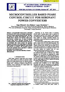
ABSTRACT
A power supply and power control circuit for providing a variable and controlled DC voltage to a DC load. The circuit includes an electrical power source; a rectifying device to
provide recti?ed alternating current from the electrical power source; a comparator device; circuitry for providing a predetermined voltage to the inverting input of the com parator device derived from the recti?ed alternating current; a sensor device to monitor a sensed value associated with the
DC load; circuitry for providing an adjustable DC voltage to the non~inverting input of the comparator; a programmable control device to receive an output from the sensor device
and provide an output to the circuitry for providing an
U.S. PATENT DOCUMENTS 2/1947
2,713,655
7/1955 Grubman
165/185
and control circuitry which is coupled between the switching
3,584,291
6/1971 Bunick et a1.
323/236
device and the output of the comparator device and is controlled by the output of the comparator device. The
3,612,970
4,187,535 4,301,658
10/1971
Braun .................................... .. 165/185
adjustable DC voltage; a switching device connected between the DC load and the recti?ed alternating current;
2,416,152
Sofan ..... ..
2/1980 Wigley et al. 11/1981
Reed ...... ..
318/721
363/16
control circuitry activates and deactivates the switching
.. 62/3.7 X
device to apply power to the DC load when the sensed value of the DC load is different than the desired set point value to maintain the sensed value at the desired set point with minimum variations therefrom.
4,459,466
7/1984 Bailey ........ ..
219/490
4,587,563
5/1986 Bendeliet al.
358/213
4,833,888
5/1989
4,844,072
7/1989 French et a1.
128/400
4,935,864
6/1990 Schmidt et al. ..
363/141
5,030,898
7/1991
Kerner et al. .
.... .. 62/3.3
Hokanson et al. .................... .. 318/146
18 Claims, 4 Drawing Sheets
US. Patent
Jun. 18, 1996
20
Sheet 1 0f 4
5,528,485
POWER SUPPLY f32
\
134
12\
J’ MICROPROCESSOR
[5*
CONTROLLER
PULSE POSITION [24
14
/148
POWER SUPPLY 82
DISPLAY f
SPEED [r146
84
SENSOR 0c MOTOR
7 f30
FIG.
12v0c-~
I
VOLTAGE 0
F] G. 3
TIME
12voc
VOLTAGE
FIG.
4
TIME
12v0c-
VOLTAGE
H
TIME
5
1
US. Patent
Jun. 18, 1996
Sheet 4 0f 4
158
FIG. 8
BRIDGE RECTIFIER
POWER CONTROL CIRCUITRY
5,528,485
5,528,485 1
2
POWER CONTROL CIRCUIT FOR IMPROVED POWER APPLICATION AND CONTROL
voltage across the DC load to maintain a set voltage or
power. Another aspect of the present invention comprises an improved direct current power supply controller scheme
This application is a continuation-in-part of U.S. patent application Ser. No. 08/330,424 ?led Oct. 28, 1994 which is a continuation of U.S. patent application Ser. No. 08/212,
utilizing a standard alternating current input voltage. The “pulse positioning” scheme places a high current transistor in the conduction mode when the nominal voltage across the
147 ?led Mar. 14, 1994, now U.S. Pat. No. 5,371,665.
load is below the desired voltage. When the high current transistor is in the non‘conducting state, a ?lter capacitor supplies the current to the load, thus providing a non
BACKGROUND OF THE INVENTION
10
isolated DC current to the load.
1. Field of the Invention The present invention relates to DC power supplies, and more particularly, but not by way of limitation, to a power
Another aspect of the present invention comprises a power control circuit for improved speed control of a DC motor to maintain thespeed thereof at a set point or a set
supply and control circuit incorporating an improved design
speed. The circuit includes an electrical power source; a
for supplying a variable DC voltage to a device.
rectifying device to provide recti?ed alternating current
2. History of the Prior Art
from the electrical power source; a comparator device;
Power supplies are widely used in industrial and com
circuitry for providing a predetermined voltage to the invert ing input of the comparator device derived from the recti?ed
mercial applications to provide DC potentials for electrical and electronic equipment. Power supplies are generally included as an integral part of equipment which requires DC potentials, but also exist as self-contained units. The primary
alternating current; a sensor device to monitor the speed
associated with the DC motor; circuitry for providing an
adjustable DC voltage to the non-inverting input of the
function of any power supply is to convert AC power to
useful DC potentials. This conversion process requires at least two and usually three operations which include recti~ ?cation, ?ltering and regulation or control.
25
comparator; programmable control device to receive an output from the sensor device and provide an output to the
Many present designs use high-frequency switching
circuitry for providing an adjustable DC voltage, the value of the output being determined by the difference between the speed of the DC motor and the set point speed; a switching
power supplies or use transformers to supply the appropriate
device connected between the DC motor and the recti?ed
alternating current; and control circuitry which is coupled
voltage or voltages. Switching power supplies tend to be expensive and run at a high frequencies possibly causing electro-magnetic interference or leakage current problems. Transformers tend to be heavy, bulky and expensive. In many applications, special transformers must be designed which increases the cost.
Two applications, among others, of the present invention include providing power to and control of the speed of DC motors, providing power for the charging of batteries, etc. DC motors would bene?t from the present invention through more e?icient power application, lighter weight, lower cost and the absence of the need for high frequency pulse width modulation (PWM) control. A variable voltage output would be provided to the DC motor depending on the voltage needed to acquire the desired motor speed. Batteries and the charging thereof would bene?t because
between the switching device and the output of the com ' parator device and is controlled by the output of the com
parator device, the control circuitry activates the switching 35
tivating the switching device when the operating speed is
40
device to provide recti?ed alternating current from the electrical power source; a comparator device; circuitry for 45
and reduced cost alternative to transformer-based linear -Current capabilities of more than ten amps DC can be 50
cost and weight required by a transformer rated as such a
providing a predetermined voltage to the inverting input of the comparator device derived from the recti?ed alternating current; circuitry for providing a predetermined voltage to the non-inverting input of the comparator device derived from the recti?ed alternating current; regulator circuitry connected between the output of the power control circuit
and the battery; and control circuitry which is coupled between the switching device and the output of the com parator device and is controlled by the output of the com
high current. In addition, the efficiency of the present
parator device, the control circuitry activates the switching 55
device to apply a constant voltage with high current capa
bilities to the regulator circuitry. BRIEF DESCRIPTION OF THE DRAWINGS
frequencies typical of switching power supplies and main
Other advantages and features of the invention will
tains a low part count. 60
SUMMARY OF THE INVENTION
point speed with minimum variations therefrom. Another aspect of the present invention comprises a power control circuit for improved charging of a battery. The circuit includes an electrical powerv source; a rectifying
power supplies or high frequency switching power supplies.
invention is greater than that obtained using a transformer. The present invention provides an improvement over the prior art by providing a smooth DC voltage for use with DC motors and the charging of batteries and eliminates the use of bulky inductors or transformers, does not operate at high
indicated by the output of the comparator device and deac below the set point speed to maintain the DC motor at the set
the present invention would provide a smaller, lighter weight
achieved for charging by the present invention without the
device to apply power to the DC motor when the operating speed of the DC motor is above the set point speed as
become more apparent with reference to the following
detailed description of a presently preferred embodiment thereof in connection with the accompanying drawings, wherein like reference numerals have been applied to like
The present invention relates to an improved power supply and control circuit for supplying a variable DC voltage to a DC load. More particularly, one aspect of the
elements, in which:
present invention comprises the pulse positioning of power
supply according to the embodiment of the present inven
to a ?lter capacitor and the DC load to apply the required DC
tion;
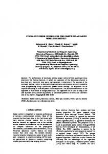
FIG. 1 is a block diagram of a DC motor having a power
5,528,485 3
4
FIG. 2 is an electrical diagram of the power supply of the present invention and the DC motor whose speed is con
non-inverting input 96 of comparator 90 and is used to adjust the control output ‘98 from comparator 90 which is input to the transistor control network 100‘via line ‘102. The control
trolled thereby;
signal is adjustable (see FIG. 3) by the pulse positioning
FIG. 3 is a view of the waveform of the adjustable DC
control circuit 92 from about zero volts DC to about 12 volts. “
reference signal applied to the comparator of the present invention;
DC and is compared to the output from voltage divider73 (see FIG. 4). The control output 98 of comparator 90, which .
‘
FIG. 4 is a view of the waveform of the signal applied to
the is constant transistor in control value butcircuit is variable 100 which in width, provides is provided the high to .
the inverting input of the comparator of the present inven-‘ tron;
.
,
10
FIG. 5 is a view of the waveform of the pulse position
output to the high current transistor of the present invention; '
FIG. 6 is a block diagram of a battery and ‘connected
current transistor 80 with “pulse positioning” control (i.e. specifying when the high current transistor 80 is conducting or not conducting) on line 104; The ‘pulse position output on line 104 to high current transistor 80 is shown in FIG. 5. The
trailing edge of the pulse varies in position as the width of the ‘pulse changes; As previously noted, the output from
battery charger having a power supply according to the embodiment of the present invention;
15
FIG. 7 is an electrical diagram of the power supply of the
battery charger of FIG. 6;
voltage divider 73 is adjustable such that you can tune the maximum voltage across the DC motor 30 to the appropriate Vmax of the motor.
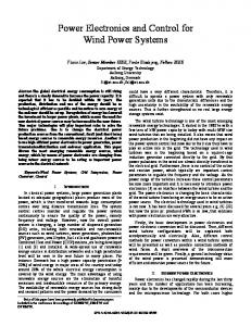
FIG. 8 is an electrical diagram of the constant power regulator shown in FIG. 6; and FIG. 9 is a block diagram of the inventive power supply
current transistor 80 is turned 011’. As the non-inverting DC
and a protection circuit therefore.
signal is increased, the pulse positioning time is increased
When the pulse positioning control circuit 92 reduces the non-inverting input of comparator 90 to 0 volts DC, the high (the width of the pulse to the high current transistor 80 is
increased). The predetermined voltage (about 12 VDC)
7 DETAILED DESCRIPTION
Referring ?rst to FIG. 1, there is shown in block diagram
25
form, a DC motor controller 20 operatively connected to a DC motor 30. DC motor controller 20 comprises a pulse
applied to the inverting input 88 of comparator 90 is tied to the fully recti?ed input waveform, and when compared to, V
the non-inverting input 96 provides pulses which are vari
able in width. The high current transistor 80 is turned on until the desired nominal voltage occurs across terminals 82 speed control circuitry 12, power supply 32 and display 14. and 84 which is necessary to maintain the speed of DC The various desired speeds of the DC motor are pro 30 motor 30. The voltage across terminals 82 and 84 is applied grammed into the microprocessor controller or speed control across the input of DC motor 30 through the hall eifect circuitry 12 and the actual speed which is desired at the current sensor 106. The output of the hall e?fect current present time of operation is selected and then displayed on sensor 106 is provided to the microprocessor controller 12
position power supply 24, a microprocessor controller or
display 14. The actual speed of the DC motor 30 is sensed by speed sensor 146 and a signal indicative of that sensed speed is input to the microprocessor controller 12 via line 148. A pulse width modulated (PWM) signal is transmitted ‘
for safety purposes. Once at the desired voltage, the high current transistor 80 is turned off and the ?lter capacitor 108 provides the power to the DC motor 30 for the balance of the
to the pulse position power supply 24 via line 134 which ‘
causes the pulse position power supply 24 to provide the
The high current transistor 80 is in the conduction state when the voltage at terminals 82 and 84 (across DC motor
appropriate power to DC motor 30 to bring the DC motor 30 to the desired speed and to maintain that speed.
30 in series with the hall effect current sensor 106) is at or.
Referring‘ now to FIG. 2, the pulse position power supply 24 comprises a power source in the form of a bridge recti?er 52 and‘ power control board or circuitry 34. A standard ‘AC
input voltage 54 (115 volts AC@60 Hz) is applied to the input of bridge recti?er 52 which provides about 103 volts DC with about 50 volts rms AC at its output across lines 56
and 58. It will be appreciated that the AC input voltage can be 115 volts AC@4OO HZ, 220 volts AC@50—60 Hz (single phase or three phase) with the proper interface elements, if
required. A voltage divider 59 comprising resistors 60 and 62 across lines 56 and 58 provides voltage regulator 64 and ?lter capacitors 66 and 68 with power through protection
cycle.
~
‘
below the nominal voltage that is desired for the selected speed of DC motor 30. The high current transistor 80 is not conducting when the voltage at terminals 82 and 84 is above the desired voltage level. When the high current transistor 80 j
is not conducting, capacitor 108 supplies the appropriate amount of current for the balance of the cycle such that the DC motor 30 sees a DC voltage with less than a 5% ripple. Transistor control network 100 comprises a FET driver
and protection device 110 (an SI9910) which will protect the comparator circuitry 90 if the high current transistor 80 fails. Capacitor 112 is a ?lter capacitor for the 12 volts DC applied to the FET driver and protection device 110 via line 114. The “pulse positioned” control output 98 from comparator 90 is input to FET driver and protection device 110 which pro
diode 70 such that the output of voltage regulator 64 is at a 55 predetermined level of about 12 volts DC on line 72. vides the proper output to the high current transistor 80 to A second voltage divider 73 comprising resistors 74 and control the conduction thereof. Resistor 116 is provided to 76 and variable potentiometer 78 across lines 56 andSS is sense any overvoltage condition and turn off the high current tunedby varying potentiometer 78 to provide the maximum transistor 80 before damage occurs to the high current desired voltage across the DC motor 30 or the maximum 60 transistor 80. Resistors 118 and 120 provide impedance desired on-time (maximum pulse position) for the high matching to ensure that the proper signal is seen at the high, current transistor (an FET) 80. Protection diode 85 is con current transistor 80. nected between terminal 82 and high current transistor 80. The pulse positioning control circuit 92 interfaces the The output from voltage divider 73 is applied via line 86 to control signal from the programmable control means 122 in the inverting input 88 of comparator 90. 65 the microprocessor controller 12 to the comparator 90 and The control signal which is output from the pulse posi comprises an opto-isolator 124, resistor 126 which is a tioning control circuit 92 is applied via line 94 to the pull-up resistor to 12 volts DC and ?lter 128 comprising
5,528,485 5
6
resistor 130 and capacitor 132. The programmable control
tor 183. Current source means 184 is connected in series
means 122 in the microprocessor controller 12 comprises a
with temperature compensated bias means 186 between terminals 28 and 158. Current source means 184 comprises resistor 188 and resistor 190 connected in series between terminals 28 and 192. Zener diode 194 is connected between
microprocessor and appropriate software and outputs a pulse width modulated (PWM) 0 to 5 volts DC control signal which is input to the power control board 34 on terminals 132 and J33 via line or cable 134. The PWM 0 to 5 volts DC
terminals 158 and 196. Temperature compensated bias
control signal is passed through opto-isolator 124 where
means 186 comprises resistor 198 connected in series with transistor 172 between terminals 158 and 192.
upon it is transformed to a 0 to 12 volt DC signal by ?lter 128 and resistor 126 and is applied via line 94 to the
In operation, the pulse position power supply 22 would
non-inverting input 96 of comparator 90.
provide an unregulated DC voltage to terminals 28 and 23 of the constant power regulator circuit 26. The constant power
In operation, speed sensor 146 provides a signal over line 148 to the microprocessor controller 12 and programmable control means 122. If the speed sensed by speed sensor 146
regulator circuit 26 would increase current limiting when the voltage of battery 140 increases such that the total power applied to the battery is constant over the charging cycle of
rises above or below a predetermined value, programmable control means 122 sends a predetermined signal to the pulse positioning control circuit 92 which converts that signal to
the battery 140. Under a low charge condition, batteries can typically take a high amount of current to begin the charging
cycle. However, with an increasing charge, it is more ef?cient to limit the charging current as the terminal voltage
the proper level of DC voltage and transmits that signal to
the non-inverting input 96 of comparator 90. The control
rises on the battery.
output 98 from comparator 90 is sent to the transistor control network 100 which then sends a proper signal to the high
Transistor 166 monitors the voltage across current sensor
means 182 (resistor 183). Thus a temperature compensated bias is applied to transistor 166 by the temperature compen bring the speed of the DC motor 30 back to the desired sated bias means 186 (transistor 172 and resistor 198). speed. Current source means 184 (diode 194 and resistors 188 and Referring now to FIG. 6, there is shown in block diagram form, a battery charger 150 operatively connected to a 25 190) applies a constant current to the temperature compen sated bias means 186. The transistor 172 bias supply applies battery 140 which is to be charged. Battery charger 150 a voltage to the base of transistor 166 which is supplemented comprises a pulse position power supply 22, as depicted in by an output voltage-dependent bias through the voltage FIG. 7, and a power regulator 26. The output of the pulse compensation means 170. Diode 174 provides an offset in position power supply 22 at terminals 82 and 84 would be connected to the input terminals of the constant power 30 the current supplied by resistor 176 as a function of the output voltage to achieve a constant power function. Tran regulator 26 and nothing else would be connected to termi sistor 166 begins to conduct when the summation of the bias nals 82 and 84. With the addition of the constant power on the base of transistor 166 and the voltage across resistor regulator, the pulse position power supply 22 would provide 183 reaches the base-emitter voltage of transistor 166. When the DC voltage and current necessary to charge batteries this occurs, diode 162 will not conduct and the supply such as the 24 volt or 48 volt batteries that are typical 35 becomes a constant power control instead of a constant batteries for use in backup power systems for telecommu current transistor 80 to control the conduction thereof to
nication equipment.
voltage controller.
With reference to FIG. 7, pulse position power supply 22 differs from the pulse position power supply 24 of FIG. 2 in
cessor controller 12 and pulse positioning control circuitry 92 are not required for the present embodiment. The pulse position power supply 22 can charge at different voltage
With reference to FIG. 9, there is shown in block diagram form, the bridge recti?er 52 operatively connected to the power control circuitry 34 (or 36). The output of the power control circuitry 34 on lines 56 and 58 include terminals 82 and 84 with capacitor 108 connected therebetween. A fuse or circuit interrupter 200 is operatively connected in line 56.
levels by locking the control signal in the full on condition
Lines 210 and 212 operatively connect the output terminals
that the display 14, switching power supply 32, micropro
by connecting the non-inverting input 96 of comparator 90
45
to line 72, which is at 12 VDC, and then adjusting poten tiometer 78 to the output voltage which is desired at termi nals 82 and 84. Therefore, whether the application is for
In order to lower the cost of pulse position power supply 22 (or 24), protection circuit 204 is added to the circuit. With the protection circuit added to the circuit, it is then possible
charging a 12, 24 or 48 VDC battery, the correct voltage can
be easily obtained by the pulse position operation.
50
and terminal 154 with voltage regulation means 156 con nected between terminal 154 and terminal 158. Voltage regulation means 156 comprises resistor 160 in series with zener diode 162. Zener diode 164 and transistor 166 are connected in series between terminals 154 and 168. Voltage compensation means 170 and transistor 172 are connected in
to use a low voltage capacitor for capacitor 108 rather than
a more expensive high voltage capacitor. The protection
With reference to FIG. 8, the input terminals 28 and 23 of the constant power regulator 26 are operatively connected to
the output terminals 82 and 84 of the pulse position power supply 22 to receive the unregulated DC voltage. Light emitting diode 152 is connected between input terminal 28
82 and 84 to a DC load 202 and to a protection circuit 204 which comprises a Zener diode 206 and an SCR 208.
circuit 204 will sense if there is a failure of the high power transistor 80 by sensing anv over voltage condition across 55
capacitor 108 and any DC load 202. If the voltage reaches a certain critical predetermined voltage, the protection cir~ cuit 204 trips (zener diode 206 will turn on SCR 208 and provide a short across capacitor 108 and any DC load 202) and a short circuit condition exists which cause fuse or
circuit interrupter 200 to activate thereby protecting capaci 60
tor 108 and any DC load 202. It is thus believed that the operation and construction of
resistors 176 and 178. Current sensor means 182 is con
the present invention will be apparent from the foregoing description. While the apparatus shown or described has been characterized as being preferred it will be obvious that various changes and modi?cations may be made therein without departing from the spirit and scope of the invention
nected between terminals 158 and 168 and comprises resis
as de?ned in the following claims.
series between terminals 28 and 158. Voltage compensation means 170 comprises Zener diode 174, resistor 176 and resistor 178 which are all connected in series. The base of transistor 166 is connected to terminal 180 which is between
5,528,485 7
8
What is claimed is: 1. A power control system for a DC motor to maintain the speed of the DC motor at a set speed, said power control
nected in series'with said recti?ed alternating current and said DC motor.
11. The system as set forth in claim. 10 further including a capacitor connected in parallel with said DC motorto supply power to said DC motor when said high current. transistor is not activated.
system comprising: rectifying means for producing recti?ed alternating cur rent when receiving an input of alternating current;
12. The system as set forth in claim 1 wherein said control means comprises a PET driver and a protection diode.‘ 13. The system as set forth in claim 1 further including‘ a ‘ circuit interrupter operatively connected in series with said recti?ed alternating current and said DC motor and a pro tection circuit connected in parallelwith said DC motor, said protection circuit comprising a zener diode operatively connected to a SCR wherein the protection circuit will trip
comparator means having an inverting 'input, a non
inverting input and an output; means for providing a predetermined voltage to the inverting input of said comparator means from said recti?ed alternating current;
.
sensor means operatively positioned to monitor the speed associated with said DC motor; means for providing an adjustable DC voltage to the
15
non-inverting input of said comparator; programmable control means to receive an output from said sensor means and provide an output to said means
speed, said method comprising the steps of;
for providing an adjustable DC voltage, the value of said output being determined by the difference between
‘ providing an electrical power source for supplying alter
nating current;
the sensed speed of said DC motor and the desired set
speed of said DC motor; switching means operatively connected between said DC motor and said recti?ed alternating current; and control means operatively coupled between said switch ing means and the output of said comparator means,
act'mg on said alternating current to produce recti?ed
alternating current; 25
said control means activates said switch means for a
providingcomparator means, having an inverting input, a non-inverting input and an output; providing a predetermined value of voltage derived from said recti?ed alternating current to the inverting input of said comparator means;
predetermined time, determined by the output from said comparator, to allow the recti?ed alternating cur~ rent to reach a desired voltage across said DC motor at which time said control means deactivates said switch ~
means, wherein the value of the desired voltage is determined by the set speed. 2. The system as set forth electrical power source is about 3. The system as set forth electrical power source is about 4. The system as set forth electrical power source is about 5. The system as set forth
and activate the circuit interrupter when the voltage across » the DC motor reaches a predetermined value. 14. A method of controlling the application of power to a DC motor to maintain the speed of the DC motor at a set
determining the operating speed of said DC motor; providing a voltage to the non-inverting input of said comparator, the value of said voltage being determined by the difference between the determined operating speed of said DC motor and the set speed;
in claim 1 wherein said 35 115 volts AC@6O Hz. in claim 1 wherein said 115 volts AC@400 Hz. in claim 1 wherein said 220 volts AC@50—60 Hz. in claim 1 wherein said
rectifying means comprises a bridge recti?er.
providing switching means operatively connected between said DC motor and a power source; and
providing control means which is operatively coupled between said switching means and the output of said comparator means, said control means activating said switching means for a predetermined time, determined by the output from said comparator, to allow the recti?ed alternating current to reach a desiredvoltage
6. The system as set forth in claim 1 wherein said means
across said DC motor at which time said control means
for providing a predetermined voltage to the inverting input
deactivates said switch means, wherein the value of the
comprises a voltage divider.
.
7. The system as set forth in claim 1 wherein said means
45
desired voltage is determined by the set speed. 15. The method as set forth in claim 14 wherein the value
for providing an adjustable DC voltage to the non-inverting input comprises an opto-isolator operatively coupled to a
of said predetermined voltage is about 12 volts DC.
pull-up resistor and a ?lter.
of said voltage provided to the non-inverting input is
8. The system as set forth in claim 1 wherein said sensor
means comprises a speed sensor operatively positioned with respect to said DC motor and providing an input to the programmable control means. 9. The system as set forth in claim 8 wherein said programmable control means comprises a microprocessor and associated software. 10. The system as set forth in claim 1 wherein said switching means comprises a high current transistor con
16. The method as set forth in'claim 14 wherein the value
adjusted by circuitry comprising an opto-isolator operatively coupled to a pull-up resistor and a ?lter.
I
17. The method as set forth in claim 14 wherein said switching means comprises a high current transistor. 18. The method as set forth in claim 14 wherein said control means comprises a FET driver and a protection 55 diode.
'