1
Improved Switching Table For Direct Power Control Of Three-Phase PWM Rectifier Amir Baktash, Abolfazl Vahedi and M.A.S. Masoum
Abstract— The switching table based direct power control (ST-DPC) of three-phase PWM rectifier is analyzed and an improved switching table (IST-DPC) is presented. The proposed switching schedule improves the quality of line current and results in better dynamic performances. In addition, the predictive direct power control (PDPC) of three-phase boost rectifier is presented and simulation results (in MATLAB/SIMULINK environment) are compared with those generated by ST-DPC and ISD-DPC approaches. Advantages and limitations of each control scheme are highlighted and conclusions regarding applications, quality of current waveforms and burden of calculations are presented.
Index Terms-- Three-Phase Rectifier, PWM, Direct Power Control and Switching Table. I. INTRODUCTION
T
he simplest type of three-phase rectifier has a diode bridge circuit with a bulk storage capacitor on the dc side. This rectifier is simple and robust but has low input power factor, high level of line current harmonics and unidirectional power flow. Due to these limitations and considering the advances in power semiconductor devices and digital signal processors, three-phase PWM rectifiers (Fig. 1) have received more attention [1]. Main advantages of PWM rectifiers are: • bidirectional power flow, • regulation of dc side voltage, • sinusoidal line current and low harmonic distortion, • near unity power factor, and • reduced dc filter size. A conventional control method of the PWM rectifiers is voltage oriented control (VOC) which is based on the control of input current [2-3]. Although this method has fine dynamic and static characteristics via internal current control loops but its performance strongly depends on the quality of the applied current control strategy. Another common control approach for PWM rectifiers is based on instantaneous direct active and reactive power control and is called direct power control (DPC) [4-6]. On the basis of hysteresis controllers output and the position of supply
line voltage space vector, proper switching states are selected from a switching table (ST) for the next sampling period. This paper investigates the switching table approach for the control of PWM rectifiers and determines the corresponding switching states. An improved switching table (IST-DPC) with lower total current harmonic distortion and less burden of calculations is proposed. The performance of IST-DPC as compared with ST-DPC and the predictive direct power control (PDPC) [7] approach is also investigated II. MATHEMATICAL MODEL OF RECTIFIER Figure 1 shows the structure of the three-phase boost PWM rectifier. R and L represent the line resistance and inductance, respectively. v a , vb , vc are line voltages and vca , vcb , vcc are ac side voltages of converter. Main equations of the converter (in dq coordinates) can be described as follows: di (1) vd = L d − Lωiq + vcd dt
diq (2) + Lωid + vcq dt where subscripts d and q represent the direct and the quadrature axis parameters, respectively. vq = L
Fig 1 Three-phase boost type PWM rectifier
The ac side voltages in respect to dc voltage and switching states in dq coordinates are: vcd =
A. Baktash and A.Vahedi are with the Center of Excellence for Power Systems Operation & Automation, Department of Electrical Engineering, Iran University of Science & Technology, Narmak, Tehran, IRAN, 16846, (emails:
[email protected] &
[email protected]). Mohammad A.S. Masoum is with the Department of Electrical Engineering, Curtin University of Technology, Perth, WA6845, Australia (email:
[email protected]).
1 2
1 6
(2S a − Sb − Sc ) ⋅ cos ωt +
( Sb − Sc ) ⋅ sin ωt
Authorized licensed use limited to: Iran Univ of Science and Tech. Downloaded on October 13, 2009 at 03:43 from IEEE Xplore. Restrictions apply.
(3)
2
vcq = 1 6
1 2
Neglecting Lω iq and Lω id terms, and reminding that the
( Sb − Sc ) ⋅ cos ωt −
(4)
(2S a − Sb − Sc ) ⋅ sin ωt
III. SWITCHING TABLE BASED DIRECT POWER CONTROL The switching table based direct power control (ST-DPC) approach uses the dc voltage error to generate command value for active power. Command value for reactive power is set zero which leads to unity power factor (Fig. 2). Active and reactive powers are calculated using line voltages and currents, and power errors are delivered to hysteresis controllers. By using controller’s outputs and the voltage space vector position, a voltage vector is selected from the switching table. The plain of voltage vector is shown in Fig. 3 and the corresponding switching table of DPC is presented in Table 1.
value of vd is constant, It could be written:
dp 3 ∝ v −v dt 2 m cd dq ∝ vcq dt where vm is the amplitude of line voltage.
(9) (10)
Fig. 3 Twelve sectors of the voltage plane used in ST-DPC TABLE I SWITCHING STATE TABLE USED IN THE ST-DPC SCHEME [5]
dp
1
dq
sector 1
2
3
4
5
6
7
8
9
10
11
12
0
6
8
1
7
2
8
3
7
4
8
5
7
1
8
8
7
7
8
8
7
7
8
8
7
7
0
6
1
1
2
2
3
3
4
4
5
5
6
1
1
2
2
3
3
4
4
5
5
6
6
1
0 Fig. 2 Block diagram of ST-DPC scheme.
When active and reactive powers are controllable, IV. DETERMINATION OF SWITCHING TABLE Applying each voltage vector (Fig. 3) to converter causes a change in active and reactive power value, therefore for each condition and each sector of the voltage plane, one of the 7 voltage vectors (that has the best effect) is selected. The equations of active and reactive powers in dq coordinates are: (5) p = v d id + v q iq
dp and dt
dq can become positive and negative. The maximum value of dt
2 vcd and vcq is V , therefore, the minimum value of 3 dc
Vdc to have a controllable active power is
3 vm [6].
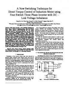
Applying each voltage vector for the interval 0 ≤ ωt ≤ 2π , we have sinusoidal vcd and vcq as shown in Fig. 4. Using this
(6) q = v q id − v d iq Assuming balanced line voltages, the rate of active and reactive power changes are as follows: di dp (7) = vd d dt dt
Figure we can determine suitable voltage vectors for every condition. Considering Fig. 4 we realize that all switching states in Table 1 are suitable except the first row. For the first row ( d p = 1, d q = 0 ) there is a better choice as shown by the
diq dq = −v d dt dt
proposed switching schedule of Table 2. In this switching table, first row of the conventional switching table is changed to obtain better dynamics performance and lower current THD.
(8)
Authorized licensed use limited to: Iran Univ of Science and Tech. Downloaded on October 13, 2009 at 03:43 from IEEE Xplore. Restrictions apply.
3
and vcq ( k + 1 ) are calculated from Eqs. 3-4 for all voltage vectors and the vector that minimizes Eq. 13 is selected.
* (k ) − v (k + 1)) + j (v* (k ) − v (k + 1)) J = (vcd cd cq cq
(13)
Fig. 5 Block diagram of PDPC scheme.
VI. SIMULATION RESULTS
Fig. 4
vcd
and
vcq by applying voltage vectors V. PREDICTIVE CONTROL STRATEGY
Fig. 5 shows the block diagram of predictive direct power control (PDPC) [7]. By using Eqs. 1-2 and 5-6, the reference values of rectifier voltage can be obtained. TABLE II PROPOSED SWITCHING TABLE FOR THE IST-DPC SCHEME
sector dp
1
dq 1
2
3
4
5
6
7
8
9
10
11
12
0
5
6
6
1
1
2
2
3
3
4
4
5
1
8
8
7
7
8
8
7
7
8
8
7
7
0
6
1
1
2
2
3
3
4
4
5
5
6
1
1
2
2
3
3
4
4
5
5
6
6
1
0
P* ( k ) L v*cd ( k ) = vd ( k ) − ⋅( R + ) + vd ( k ) Ts L P( k ) Q( k ) ⋅ + Lω ⋅ Ts vd ( k ) vd ( k )
(11)
L Q( k ) P( k ) v*cq ( k ) = − ⋅ + Lω ⋅ Ts vd ( k ) vd ( k )
(12)
Simulations have been performed for ST-DPC, IST-DPC and PDPC methods using the Matlab/Simulink software. System parameters are presented in Table 3. Simulations results for a step change in command value of active power from 2kw to 4kw are compared in Fig.6. It is clear that reactive power in ST-DPC has more ripples and therefore its line current has a higher THD. In PDPC method reactive power is smoother and its line current has a lower THD (Fig. 7). Table 4 presents the THD of the line current for the three control approaches. In order to compare the switching losses, the number of switching actions in a specified time is used as an index. Figure 8 illustrates the numbers of switching versus time for the three corresponding control approaches. As expected, the PDPC approach has better line current quality (e.g., THD= 4.3%) and shorter response time, however, it requires longer computing time (e.g., more number of switching actions as presented in Fig. 8) and its performance depends on line parameters. It can be observed that IST-DPC successfully tracks command active power and effectively limits reactive power to zero. Fig. 7 shows the line current for a sinusoidal supply voltage. It is clear that current quality in IST-DPC is as well as PDPC, however, the switching losses in IST-DPC are lower than other methods.
where P* is active power reference, P and Q are actual active and reactive powers and TS is the sampling time. vcd ( k + 1 )
Authorized licensed use limited to: Iran Univ of Science and Tech. Downloaded on October 13, 2009 at 03:43 from IEEE Xplore. Restrictions apply.
4
IST-DPC
ST-DPC
IST-DPC PDPC
PDPC Fig. 7 Line current waveforms for sinusoidal supply voltages
Fig. 6 Simulation results for a step change in active power TABLE III PARAMETERS OF THE POWER CIRCUIT Line voltage amplitude ( v m )
220 V
Line frequency (f )
50 Hz
DC bus voltage ( Vdc )
500 V
Line resistance (R)
0.1 Ω
Line inductance (L)
10 mH
DC link capacitor (C)
500 µF
Sampling frequency ( f s )
50 kHz
Fig. 8 Number of switching
VII. CONCLUSIONS
TABLE IV THD OF LINE CURRENT THD [%]
Supply voltage
Sinusoidal
DPC
IDPC
PDPC
6
5
4.3
7.5
7.8
8.9
Non-sinusoidal ( 5 % of fifth harmonic
In this paper the switching table based direct power control approach of three-phase PWM rectifier is analyzed and an improved switching table is presented. The performance of the proposed control scheme as compared with the conventional ST-DPC and PDPC methods is investigated. Based on the simulations results: • All three control approaches track the command active power and effectively limit reactive power. • The PDPC approach has the lowest line current harmonic distortion; however, it requires longer computing time and its performance depends on line parameters. • The current quality of the proposed IST-DPC approach is better than the ST-DPC and is as low as the PDPC. • IST-DPC requires less switching actions as compared with the other two control methods. The performance of the proposed IST-DPC approach is better than the conventional ST-DPC and comparable with the PDPC; however, it is a superior choice since it has higher efficiency due to less number of required switching actions.
Authorized licensed use limited to: Iran Univ of Science and Tech. Downloaded on October 13, 2009 at 03:43 from IEEE Xplore. Restrictions apply.
5
BIOGRAPHIES VIII. REFERENCES [1] J.R. Rodríguez, J.W. Dixon, J.R. Espinoza, J. Pontt and P. Lezana, “PWM Regenerative Rectifiers: State of the Art”, IEEE Trans. on Industrial Electronics, vol.52, no.1, February 2005. [2] M.P. Ka´zmierkowski and L. Malesani, “Current Control Techniques for Three-Phase Voltage-Source PWM Converters: A survey”, IEEE Trans. on Industrial Electronics, vol. 45, pp. 691-703, 1998. [3] F. Blaabjerg and J.K. Pedersen, “An Integrated High Power Factor Three-Phase AC-DC-AC Converter for ACmachines Implemented in one Microcontroller”, IEEE PESC Conference, pp. 285-292, 1993. [4] M. Malinowski, M.P. Kazmierkowski, and A.M. Trzynadlowski, “A Comparative Study of Control Techniques for PWM Rectifiers in AC Adjustable Speed Drives”, IEEE Trans. on Power Electronics, vol.18, no. 6, November 2003. [5] T. Noguchi, H. Tomiki, S. Kondo, and I. Takahashi, “Direct Power Control of PWM Converter Without Power-Source Voltage Sensors”, IEEE Trans. on Industrial Electronics, vol. 34, pp. 473–479, May/June 1998. [6] T. Ohnishi, “Three-Phase PWM Converter/Inverter by Means of Instantaneous Active and Reactive Power Control”, in Proc. IEEE IECON'91, pp. 819-824, 1991. [7] P. Antoniewicz and M.P. Ka´zmierkowski, “Predictive Direct Power Control of Three-Phase Boost Rectifier”, Bulletin of the Polish Academy of Sciences Technical Sciences, vol. 54, no. 3, 2006. .
Amir Baktash was born in Isfahan on May 17, 1982. He received the B.S degree in Electronic Engineering & M.S Degree in Electrical Engineering from Iran University of Science & Technology in 2004 and 2007 respectively. His research interests include variable speed drives, FACTs devices, motor control, DSP Microcontrollers, Power electronics and automotives electronics.
Abolfazl Vahedi received his B.S, M.S and Ph.D in 1989, 1992 and 1996 from Ferdowsi Mashhad University, Institut nationale polytechnique de Lorraine (INPL-France) and INPL all in electrical engineering respectively. He is Associate Professor in Department of Electrical Engineering of Iran University of Science & Technology. He has directed several projects in the area of electrical machines and drives. His research interests are mainly design, implementation and optimization of electric machines and drives. He is a member of IEE, SEE. Mohammad A.S. Masoum (SM’ 05) received his B.S., M.S. and Ph.D. degrees in Electrical and Computer Engineering in 1983, 1985, and 1991, respectively, from the University of Colorado at Boulder, USA. Currently, he is a Faculty Member at the Electrical and Computer Engineering Department, Curtin University of Technology, Perth, Australia. Dr Masoum is a senior member of IEEE.
Authorized licensed use limited to: Iran Univ of Science and Tech. Downloaded on October 13, 2009 at 03:43 from IEEE Xplore. Restrictions apply.