obtain systems that allow the control and management of the network monitoring system in real time identification of weak points of the network, among others [2] ...
1
Power Flow Management in Hybrid Power System Using Flatness Based Control G. V. Santos, F. H. de Oliveira, A. F. Cupertino, T. A. Pizziollo, H. A. Pereira
Abstract – Several techniques of control require a linear mathematical model in order to get an inverse dynamic solution. However, in more complex systems the linearization is not enough to solve the problem. A new class of systems called "flatness systems" that allows the entire description of the state’s trajectories, and so to improve the dynamic response of those systems. This paper introduces a simulation of the power flow control of hybrid power system using the technique of planning. Index Terms – Energy management, flatness control, DC / DC Boost converter.
I. INTRODUCTION
T
HE increase in world population coupled with the economic development of countries and industrialization leads the increasing in energy demand worldwide. To fill it, it is necessary to invest in new energy sources and increase the efficiency of the ones that already exists. In this context, the concept of the smart grid, which is based on the intensive use of automation, computing and communication in managing the generation, transmission and distribution of energy [1]. Through the use of these, one can obtain systems that allow the control and management of the network monitoring system in real time identification of weak points of the network, among others [2] . In the last decade, the implementation of the concept of smart grid systems in renewable energy generation has achieved excellent results [3]. They are interesting because its use allows the reduction of CO2 emissions and is thus an important way of generating energy today. However, the performance of these sources is influenced by environmental conditions such as solar radiation, wind speed, rainfall, among other factors, making these sources real challenges for the inclusion of the concept of smart grid [4]. In order to get a greater reliability of these systems, we use storage systems for power and energy density. This is possible thanks to the integration of batteries, super capacitors and flywheel, increasing the complexity of the control and the energy management in systems for hybrid sources. Hybrid systems, simple configurations that connect two or more power sources in one continuous bus, have disadvantages. The voltage in all of the sources has to be the same, decreasing its flexibility. Another disadvantage is that the power delivered by the source is given by hybridizes potential delivered by each of the sources connected to it, being limited by the characteristics of each one [5].
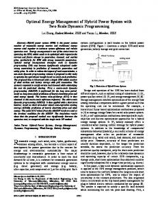
An alternative solution to this problem is the connection of different sources through static converters. This work proposes a hybrid modeling of a source with solar panel and battery with a flatness control technique to ensure the reliability of the DC bus, where the loads are connected, for an isolated system. The flatness-based control is useful in situations where an explicit trajectory generation is required. It has recently been studied in many applications because it is appropriate for robustness, predictive control, trajectory planning and constraints handling [5] [6] [7]. Another advantage of this technique is when the flat output is used, the trajectory is controlled, evolution of the trajectory of state and control variables are well known even in transient state [8]. Differently from the other work [7], that used super capacitors as an auxiliary source of energy, this paper proposes the use of batteries because they can reduce costs considerably in the possible installations in micro grids and smart grid. II. DESCRIPTION OF THE SYSTEM In distributed power systems, various sources of energy, renewable or non-renewable, can be connected to a single DC bus and then to the grid through an inverter. The connections between different types of sources featuring a hybrid source are shown in Fig. 1. The use of different energy sources in the same bus requires a control strategy that manages the energy flow between the sources that provide the best system performance. Managing the energy flow becomes a critical factor in the concept of smart grid.
Fig. 2. Sistema Híbrido entre Painel e Bateria.
The operation modes of the hybrid system that consist of solar panels and batteries are: Normal mode: Load power is positive and it is less powerful than the maximum of the main source (panel). In this
2
mode the main source provides all the power demanded by the load and the secondary source, the battery, which is maintained charged or charging. Overload Mode: Power load is positive and greater than the power supplied from the main source. In this mode, the secondary source provides additional power to the DC bus, offsetting the energy deficit and ensuring the control of the voltage at the load. The battery is in discharging mode. Regenerative mode: The DC bus voltage increases. The secondary DC converter control’s regulates the bus voltage allowing the absorption of energy by the supercapacitor.
IV. MODELING OF THE CONVERTERS The simulated system is shown in Fig. 3. According to [13], the total loss of one Boost (eddy current loss and core hysteresis, ohmic conduction and switching losses of semiconductors) can be modeled by two resistances (serial and parallel); their analytical expressions depend on the operating point and the system parameters, so the total loss can be written in (7). �����_
III. FLATNESS SYSTEM A flatness system is a system in which all state variables and control variables can be expressed in terms of output path and an ended number of its derivatives without integration of the differential equations [6], [9], [10]. Differentially, flat systems are useful in situations where explicit trajectory generation is required. Since the behavior of flat system is determined by the flat outputs [11]. The flat systems’ behavior is determined by its output. It is possible to plan the desired trajectory of the outputs and determine the control system. �� = ���, �� ; � � With � inputs �, � �
(1 )
The system is said to be plane if there is an output path with a dimension m and two integers r and s which may be applied into the equations (2), (3), e (4) [8]. � = ��� , �� , �� , … , � � = Ø��, �, �� , … , ���� � � = ���, �� , … , � ��� �
� = ���, �� , … , � ����� �
(2 ) (3 )
� = ���, �� , … , � ����� �
(6)
The size of the output path is equal to the system commands number. Moreover, there is not a single output parameter and we can always find flat outputs by doing a physical interpretation of the system [12]. In 1992, Flies [6] studied the feedback linearization problem in the context of differential algebra. Thereafter, he introduced the concept of differential flatness.
'() �̂*
(7 )
1 C V� 2 � �4 . 1 y� = C� V�� 2 y� =
(8)
Determining φ� and φ� :
2y� 9 �y � 7 V� = φ� � = : C�
(4 )
(5)
= "#�$̂� +
The loss of a Boost converter operating in continuous conduction mode can be modeled with more than 90% for two nonlinear resistors, one in series (r,� ,$�� ) and the other one in parallel (r-� , r-� ). In this paper, on the operating point, the total loss of the two resistances were simplified in two constant resistances. The stored energy in the system will be a potential output flat. In the simplified control, it is considered that the electromagnetic energy stored in the inductance is small compared to the energy stored in capacitors [14]. Therefore, the latter is chosen as a flat candidate for the system. We will also use a law of closed-loop control and monitoring for the correction of the trajectory [15], [16], [17]. Thus,
8 2y� 7V� = φ��y� � = : C� 6
All dynamic behavior of the system is given by its outputs. Any trajectory of the system is defined by (5) e (6): � = ���, �� , … , � ��� �
� !�
4
(9)
For a physical analyze of Fig. 3, is obtained that: � � @� 9P� = P� + y� � − i>? @� + $� A � C + � 7 @B! $>� 8 7 6
�� � @� � P� = PD + y� � + $� A C + @� $>�
4
(10)
3
Fig. 3. Hybrid system simulated.
Boost converter er output is necessary to adjust the voltage on the capacitor `� . Therefore, @�ST) is constant.
Thus, ' ) 9 A��� + �� − P-[ + N C^ K �*N 7 P = 2 PE�FGH J1 − L1 − ] 7 � PE�FGH 7 I \4 8 ) ' �� � + PD + ) ^ 7 K �*) L P� = 2 PE�FGH J1 − 1 − 7 ] PE�FGH 7
6
I
(11)
Fig. 4. Reference energy.
\
� � , �� � � = P� When ψ��� , ��� , �� , �� � � = P� and ψ�� Where PE�FGH =
'N )
O �)
and PE�FGH =
) 'PQR
O � �N
are the maximum
power that the converters can transfer by the battery and by the solar panel. It is possible to check that this system is flat. We used the control law given by (11) to correct the imperfections and disorders in the modeling, and ensure that the system track the reference trajectory [18], [14].. The variable � represents the state and the reference ��ST . � y� + 2ξω�yUVW − y� + ω� Z� �yUVW − Z�yUVW − y� = 0 4 . � y� = y� UVW + 2ξω�yUVW − y� + ω Z�yUVW − y�
(12)
For the generation of the trajectory that is in an initial resting state to a second end resting state used to filter a second-order unity gain as suggested by [19]. [19] The frequency and damping pulse are adjusted to the desired dynamics. The reference for the power control loop is illustrated in Fig. 4.. The block diagram of the control plan is presented in Fig. 5.. With input potential the reference is achieved by the reference current as shown in Fig. 6. After the acquirement of this value, it is used a PI controller to control the output current. The difference in control of both converters is the voltage references @�STN and @�ST) . For the
Fig. 5. Power controller [18].
Fig. 6. Current control.
Considering the control of the Boost converter in the battery side, the variable �� should limit the power supplied by solar panel and respect their limits of operation. Therefore the capacitor voltage `� must be contained in the interval jVk-- − rpvimpp−Vd, Voc [17]. In continuous state, the power consumed by the load must be supplied by solar panel and the battery must be charged. @��ST is a function of i�, VgEh and @B! lmn : @��ST = @>? − $>? "� − @i + o p@B! − @B!
lmn
q
(13)
4
Where K is an adjustment control parameter. Note that if the panel is unable to provide the power required by the load, the battery will supply the difference.
Tab. 1. Parameters of the solar panel.
Parameter arameter maximum power open-circuit circuit voltage short circuit current maximum power voltage current maximum power series resistance of the panel parallel resistance of the panel
Value 48 W
22.1 V
2,89 A 18.6 V
2.59 A
1.35 Ω
73.66 Ω
Tab. 2. Parameters of the lead acid battery.
Fig. 6. Diagram of planned trajectory calculation of ���ST
The planning trajectory to manage the energy in the system can be shown in Fig. 6.
Parameter
Value
nominal voltage
10 Ah
12 V
capacity Stress of maximum load Rated current discharge internal Resistance
13.07 V 3 A
0.012 Ω
V. RESULTS Tab.1 shows the parameters of the simulated system. system In Fig. 7 it can be observed the change in the output reference DC voltage on the bus at the time of 1 second. second It is noted an increase in the current demanded by the bus because of the reference voltage change in the time 20 seconds. Fig. 8 shows the power flow corresponding to the solar panel, battery and load. The dynamic behavior condition for lifting power on the bus can be observed graphically. There is a transient variation on the load and the battery supplies the power needed to prevent collapse of the DC bus voltage. Moreover, when the power generated by the panel is less than the load demands, the battery supply the exceeding. (A)
(B) Fig. 7. Initial and final reference 23 V and 50 V load change
Fig. 8. Dynamics of hybrid system (A). Dynamics of hybrid system in the he moment of load variation (B).
5
VI. CONCLUSIONS In this paper, the flatness control with multi source have been explained. This control was simulated for a load and output voltage variation. The results presented show that the planning control allows to adjust the voltage supplied for different loads. They promote the control of power flow at the interface between the solar panel and the battery. This technique improves the reliability of the system, controlling the power flow and holding power management. This way a reduction in the system’s cost can be achieved. In general, the main source was projected with a value bigger than the nominal load. In transients moments or in rush current, the management of the energy allows suitable operation of the load. This technique does not require a switching algorithm control, what is the main advantage to manage energy systems. This way it is possible to operate in different stages even charging or discharging the battery. VII. REFERENCES [1] D. M. Falcão, "Integração de Tecnologia para Viabilização da Smart Grid," 2010. [2] G. Q. Tang, "Smart grid management & visualization: Smart Power Management System," CEWIT, pp. 1-6, Nov. 2011. [3] Z. A. Vale, H. Morais and H. Khodr, "Intelligent MultiPlayer Smart Grid Management Considering Distributed," Power and Energy Society General Meeting, pp. 1 - 7, 2010. [4] A. Molderink, V. Bakker, M. G. C. Bosman, J. L. Hurink and G. J. M. Smit, "Management and Control of Domestic Smart Grid," IEEE TRANSACTIONS ON SMART GRID, vol. 1, pp. 109 - 119, 2010. [5] A. Payman, S. Pierfederici and F. Meibody-Tabar, "Energy control of supercapacitor/fuel cell hybrid power source," Energy Conversion and Management, vol. 49, pp. 1637 - 1644, 2008. [6] M. Fliess, J. LÉVINE, P. MARTIN and R. Pierre, Sur les Systèmes non Linearies Differentiellement Plats, 1 ed., C.R. Acad. Sci Paris, 1992, pp. 619-624. [7] P. Thounthong, P. Mungporn and B. Davat, "A Nonlinear Control Approach to the Energy," ICEM, pp. 1 - 6, 2010. [8] M. ZANDI, Flatness Based Control of a non-ideal DC/DC Boost Converter, Shahid Beheshti Univ., Tehran, Iran: IECON 2011 - 37th Annual Conference on IEEE Industrial Electronics Society, 2011. [9] A. Shahin, M. Hinaje, J.-P. Martin, S. Pierfederici, S. Rael and B. Davat, High Voltage Ratio DC-DC Converter for Fuel-Cell Applications, vol. 57, IEEE Transactions on Industrial Electronics, 2010. [10] B. LAROCHE, Commande par platitude, vol. 1, Paris: Ecole Nationale Supérieur de Technique Avancées, 2005. [11] M. van Nieuwstadt, M. Rathinam and R. Murray, "Differential flatness and absolute equivalence," Decision
and Control, pp. 326 - 332, 14-16 Dec 1994. [12] P. Martin and R. Pierre, Sytèmes plats: planification et sivre de trajectoires, Paris: École des Mines de Paris Centre Automatique et Système, 1999. [13] A. Shahin, A.Payman, J.-P. Martin, S.Pierfederici and F. Meibody-Tabar, "Approximate Novel Loss Formulae Estimation for Optimization of Power Controller of DC/DC Converter," Annual Conference on IEEE Industrial Electronics Society, pp. 373 - 378 , 7-10 Nov 2010. [14] G. V. Santos and H. A. Pereira, "modelagem, simulação e construção de um conversor boost utilizado controle por planificação (flatness control)," Congresso Brasileiro de Automatica, Setembro 2012. [15] A. PAYMAN, Contribution à la Gestion de L'Energie dans les Systèmes Hybrides Multi-souces Multi-charges, vol. 1, Nancy, Département de Formation Doctorale < Electrotechnique - Electronique>: L'institut National Polytechnique de Lorraine, 2009. [16] M. Zandi, A. Payman, J.-P. Martin, S. Pierfederici, B. Davat and F. Meibody-Tabar, "Energy Management of Fuel Cell/Supercapacitor/Battery Power Source for Electric Vehicular Applications," ieee transactions on vehicular technology, VOL 60, FEVEREIRO 2011. [17] M. Zandi, A. Payman, J.-P. Martin, S. Pierfederici, B. Davat and F. Meibody-Tabar, Flatness based control of a hybrid Power source with Fuel cell/Supercapacitor/Battery, Vandoeuvre Les NANCY, Lorraine : IEEE, 2010. [18] P. Thounthong, "A New Control Law Based on the Differential Flatness Principle for Multiphase Interleaved DC–DC Converter," IEEE Transactions on Circuits and Systems Part II: Express Briefs , vol. 57, no. 11, pp. 903 907, 2010. [19] M. ZANDI, Contribution au Pilotage des Sources Hybrides d'Energie Electrique, vol. 1, L. N. P. d. Lorraine, Ed., Nancy, Département de Formation Doctorale: NANCY Université - L'institut National Polytechnique de Lorraine, 2010.
6
VIII. BIOGRAPHIES Guilherme Vianna Santos was born in VilhaVelha/ES, 1989. He joined the Electrical Engineering course at the Federal University of Viçosa (UFV) in 2007. Scholarship program was in Capes / BRAFITEC exchange of Brazil-France école nationale supérieure 2010-2011 2011 in d'électricité et de Mecanique - Nancy / France. France Currently, performs work in the area of electronics, power electronics, automation and control applied to renewable energy.
Fernando Henrique de Oliveira was born in Contagem, Brazil. He is student of Electrical Engineering at Federal University of Viçosa, Viçosa, Brazil. He works with Power Systems, especially with photovoltaic energy and control applied to converters.
Allan Fagner Cupertino was born in Visconde do Rio Branco, Brazil. He is student of Electrical Engineering at Federal University of Viçosa, Viçosa, Brazil. Currently is integrant of GESEP, where develop works about power electronics applied in renewable energy systems. His research interests include solar photovoltaic, wind energy, control applied on power electronics and grid integration of dispersed generation.
Tarcísio de Assunção Pizziollo Graduated in Electrical Engineering from the University Federal of Juiz de Fora (1984), Masters in Agricultural Engineering from the Federal University of Viçosa (1992), Specialization in Industrial Automation from Federal University of Minas Gerais (1995) and Ph.D. in Electrical Engineering from the Federal University of Minas Gerais (2002). Currently, Associate Professor at the Federal University of Viçosa. At UFV, he was Coordinator of the course of Electrical Engineering, Head of Department of Electrical Engineering, Engineering Special Advisor to the Rectory of Education and Director of the School Register Heverton Augusto Pereira (M’12) received the B.S. degree in electrical engineering from the Universidade Federal de Viçosa (UFV) (UFV), Brazil, in 2007, the M.S. degree in electrical engineering from the Universidade Estadual de Campinas (UNICAMP), Brazil, in 2009, and currently is Ph.D. student from the Universidade Federal de Minas Gerais (UFMG), Belo Horizonte, Horizonte Brazil. Since 2009 he has been with the Department of Electric Engineering, UFV,, Brazil. His research interests are wind power, solar energy and power quality.