Oct 28, 1996 - 180/652. Field of Search . ... output from an engine to a crankshaft 56, and expressed as the product of
USO0RE38790E
(19) United States (12) Reissued Patent
(10) Patent Number: US (45) Date of Reissued Patent:
Maeda et al.
(54) POWER OUTPUT APPARATUS, METHOD OF
(56)
References Cited
CONTROLLING POWER OUTPUT
U.S. PATENT DOCUMENTS
APPARATUS, AND DRIVING SYSTEM WITH POWER OUTPUT APPARATUS INCORPORATED THEREIN
3,683,249 A 3,789,281 A
(75) Inventors: Tomoharu Maeda, Toyota (JP); Yoshihide Nii, Anjo (JP); Shoichi Sasaki, Okazaki (JP); Takeshi Kotani, Nisshin (JP); Eiji Yamada, OWariasahi (JP); Yasutomo Kawabata, Aichi-ken
PCT Filed:
Oct. 28, 1996
PCT No.:
PCT/JP96/03157
May 5, 1998
Kiuchi et al.
7/1997
Takeuchi et al. . . . . . .
A
.....
. . . .. 322/18 . . . .. 322/16
8/1998 Yamada et al. .......... .. 180/65.2 9/1998 Shamoto et al. .... .. 318/139 9/1998 Yamada et al. ............. .. 318/77
EP JP JP JP JP JP JP
0 725 474 A1 49-043311 50-30223 51-22132 53-133814 55-1030100 7-135701
8/1996 4/1974 3/1975 7/1976 11/1978 8/1980 5/1995
output from an engine to a crankshaft 56, and expressed as the product of its revolving speed and torque, to be con verted to the poWer expressed as the product of a revolving
Related US. Patent Documents Reissue of:
6,087,734
Issued:
Jul. 11, 2000
Appl. No.:
09/068,208
Filed:
May 5, 1998
ABSTRACT
A poWer output apparatus 20 includes a clutch motor, an assist motor, and a controller. The clutch motor and the assist motor are controlled by the controller to enable the poWer
PCT Pub. Date: May 22, 1997
speed and a torque of a drive shaft and to be output to the drive shaft. The engine can be driven at an arbitrary driving point de?ned by a revolving speed and a torque, as long as the energy or poWer output to the crankshaft is identical. A
desired driving point that attains the highest possible effi
Foreign Application Priority Data
Nov. 14, 1995 Jun. 26, 1996
4/1997
5,650,713
(Continued)
(57)
(87) PCT Pub. N0.: WO97/18101
(30)
5,621,304 A
Primary Examiner—Nicholas Ponomarenko (74) Attorney, Agent, or Firm—Oliff & Berridge, PLC
§ 371 (6X1),
(64) Patent No.:
Shibata ..................... .. 318/205 Shibata ........ .. 318/696
FOREIGN PATENT DOCUMENTS
(73) Assignee: Toyota Jidosha Kabushiki Kaisha, Toyota (JP) (21) Appl. No.: 10/191,281
(2), (4) Date:
8/1972 1/1974
5,791,426 A 5,801,497 A 5,804,934 A
(JP)
(22) (86)
RE38,790 E Sep. 6, 2005
(JP) ........................................... .. 7-321060 (JP) ........................................... .. 8-186736
ciency With respect to each amount of output energy is determined in advance. In order to alloW the engine to be driven at the desired driving point, the controller controls the clutch motor and the assist motor as Well as the fuel injection
(51)
Int. Cl.7 ............................................... .. F02N 11/06
(52)
US. Cl. ..................... .. 290/40 C; 322/16; 318/140;
(58)
Field of Search ........................... .. 290/40 C, 40 B;
180/652
322/16, 14, 15; 318/77, 9, 140; 180/652
CONTROL CPU
and the throttle valve position. Such control procedures of the poWer output apparatus enhance the energy efficiency of the Whole poWer output apparatus.
96 Claims, 36 Drawing Sheets
US RE38,790 E Page 2
US. PATENT DOCUMENTS 5,818,116 A
10/1998 Nakae et a1. ........... .. 290/38 R
5,914,575 A 5,917,248 A 5,920,160 A
6/1999 Sasaki ...................... .. 318/150 6/1999 Seguchi et a1. ............. .. 290/31 7/1999 Yamada et a1. .............. .. 318/9
5,903,113 A
5/1999 Yamada et a1. ............. .. 318/10
5,935,040 A
8/1999 Tabata et a1,
5,905,346 A 5,909,094 A
5/1999 Yamada et a1. ............. .. 318/50 6/1999 Yamada et a1. ........... .. 318/140
5,936,312 A 5,942,862 A
8/1999 Koide et a1. ............ .. 290/40 R 8/1999 Yamada et a1. .............. .. 318/9
477/3
U.S. Patent
Sep. 6,2005
Sheet 1 0f 36
US RE38,790 E
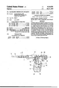
Fig. 1
20
5O
30
SV
40
39 $3235 36 as u. 38 a3
1.5
1.8
4249
+
_/91
99L1
94
_ BATTERY
92
-
95 96
Tn
T
Tn
.
Tr 3 ms
(
97
|
CONTROL CPU ‘
i
|__
_J' 65
64
U.S. Patent
Sep. 6,2005
Sheet 2 0f 36
US RE38,790 E
Fig.2
30
1.0
5% 32 £35 36 3e 38%
34
56
1.3
U.S. Patent
Sep. 6,2005
Sheet 3 0f 36
US RE38,790 E
Fig.3
r
70
EF I ECU
ST
5g
51 62
52
E o
82
30,40f :3 2;
$6 CONTROLLER < A \ 84
\
79
U.S. Patent
Sep. 6,2005
Sheet 4 0f 36
US RE38,790 E
Fig.4
T TORQUE T
T2
T1
REVOLVING SPEED N
i)
U.S. Patent
Sep. 6,2005
Sheet 5 0f 36
US RE38,790 E
Fig.5
Q TORQUE CONTROL
>
INPuT REVOLVING SPEED Nd
/S1OO
0F DRIvE SHAFT
INPUT AccELERAToR PEDAL
r5101
POSITION AP
Td>lIlkxN e
I APdkPd-PB
r5190
S192
APd>Pref o
YES
F’dhpezl-pref
5196
T|< SET TARGET ENGINE TORQUE Te* fSZOO AND TARGET ENGINE sPEED Ne:
Pd=Te>II< CONTROL CLUTCH MOTOR
I/“SZOZ
‘I CONTROL ASSIST MOTOR
f5204
CONTROL ENGINE
L/‘52O6
@
U.S. Patent
Sep. 6,2005
Sheet 15 0f 36
US RE38,790 E
Fig.1?
AP\ AP2 ______ __F____________ ACCELERATOR PEDAL POSITION
AP]
P eA
P e 2
OUTPUT ENERGY
I
‘
FROM ENGINE
I P e 1
T C Jr
I
I
|
I
I
k
I
l
r 1 l '
t 2| I
I
|
I I
| l
t 1
t 2
\
nus t
T c 2
TORQUE 0F CLUTCH MOTOR
Tc I
TIME 1'.
U.S. Patent
Sep. 6,2005
US RE38,790 E
Sheet 16 0f 36
F i g. 1 8
C ASSI ST MOTOR CONTROL? 5210
SET TORQUE COMMAND VALUE Ta* OF ASSI ST MOTOR
INPUT ROTAT IONAL ANGLE
0 d OF DRIVE SHAFT
MEASURE ASSIST MOTOR CURRENTS
Iuc.
fSZTZ
I v c
TRANSFORMATION OF COORDI NATES
lua Iva
[ ] H —sin (Gd-I20) sin6d][ ] Ida Iqa
-c0s (6d- I 20) cos6d
I COMPUTE VOLTAGE COMMAND VALUES
Vda=KplAlda+ZKi lAIda
Vqa=Kp2AIqa+ZKi2AIqa AIda=Ida>K-I da
AIqa=Iqa>IK-1d'c AIqc=Iqc>K—lqc
I
{5254
TRANSFORMATION OF coonomnes OF VOLTAGE COMMAND VALUES
[vuc _ F‘Q’ [cos-6c Vvc _ COS (BC-1
20) -s -s ii nn60 (Oc-l 20)
PWM CONTROL
RET
Vdc Vqc