Süleyman Demirel Üniversitesi, Fen Bilimleri Enstitüsü Dergisi, 12-1(2008),58-64
A Study on Power Quality Improvement in PWM Controlled AC Voltage Controller Ahmet ALTINTAŞ
Dumlupınar University, Technical Education Faculty / KUTAHYA Received:15.06.2007, Accepted: 05.02.2008 Abstract: A lot of topologies of pulse-width modulated (PWM)-AC controllers for single-phase and three-phase systems are proposed up to date. PWM-AC controllers have important advantages compared with the phase-controlled AC controllers using thyristors and triacs. The PWM-AC controller has sinusoidal current waveforms, smaller THD values, better power factor, faster dynamics, and smaller input/output filter. This article presents a novel control technique for application to PWM-AC controllers with ability of generating fewer harmonics. In the proposed control method, both the traditional AC voltage controllers and the PWM-AC controllers are combined; and smaller THD values are obtained. Thus, the harmonic pollution in the power system will be reduced; and consequently, the power quality will be increased. For this purpose, computer simulations are performed in order to investigate the proposed controller performance. The obtained results are compared with the conventional PWM-AC controller. Key Words: Power quality, Harmonics, AC controller, PWM-AC controller
DGM Kontrollü AC Gerilim Kontrolcülerde Güç Kalitesini Arttırma Çalışması Özet: Günümüze kadar bir fazlı ve üç fazlı sistemler için birçok darbe genişlik modülasyonlu (PWM)-AC kontrolcü yöntemi sunulmuştur. PWM-AC kontrolcüler, tristör ve triyak kullanan faz kontrollü AC kontrolcüler ile karşılaştırıldığında önemli avantajlara sahiptir. PWM-AC kontrolcüler, sinüzoidal akım dalga formlarına, daha düşük THD değerlerine, daha iyi güç faktörlerine, daha hızlı bir tepkiye ve daha küçük giriş/çıkış filtresine sahiptir. Bu makale, daha az harmonik üretme yeteneğine sahip PWM-AC kontrolcü uygulamaları için yeni bir kontrol tekniği sunmaktadır. Sunulan kontrol yönteminde, geleneksel AC gerilim kontrolcüsü ile PWM-AC kontrolcüsü birleştirilmiş ve daha düşük THD değerleri elde edilmiştir. Böylece, güç sistemlerindeki harmonik kirlilik azaltılmış ve dolayısıyla, güç kalitesi yükseltilmiştir. Bu amaçla, sunulan yöntemin performansını araştırmak amacıyla bilgisayar simülasyonları gerçekleştirilmiştir. Elde edilen sonuçlar geleneksel PWM-AC kontrolcü ile karşılaştırılmıştır. Anahtar Kelimeler: Güç kalitesi, Harmonikler, AC kontrolcü, PWM-AC kontrolcü ______________________________________
Introduction control elements of such controllers. Such techniques offer some advantages as simplicity and ability of controlling large amount of power economically. However, delayed firing angle causes discontinuity and plentiful harmonics in load current, the size of the passive circuit becomes bulky and also a lagging power factor occurs at the AC side even though the load is completely resistive especially when the firing angle increases (Nabil, 1997; Arrilaga et al., 1985; Balci and Hocaoglu, 2005).
There are three basic types of AC to AC converters. The simplest ones, the AC voltage controllers, allow controlling the output voltage only, while the output frequency is the same as the input frequency. The second one is the cycloconverter. In cycloconverters, the output frequency can be controlled, but it is at least one order of magnitude lower than the input frequency. In both the AC voltage controllers and cycloconverters, the maximum available output voltage approaches the input voltage. The last one is the matrix converter. Because of having no inherent limits on the output frequency, matrix converters are most versatile, but the maximum available output voltage is about 15% lower than the input voltage (Kazmierkowski et al., 2002; Bose, 2002).
The switching mode power conversion gives high efficiency; but the main disadvantage is that harmonics are generated at both the supply and load sides due to the nonlinearity of switches. The harmonic currents generated by the power electronics related-equipment flow through the utility system and cause various power quality problems. Most of the power switches have different operating conditions; thus, they generate different order and different amplitude harmonics. Due to the increasing application of power electronic equipments, more and more energy is transmitted at non-sinusoidal voltage and current,
AC voltage controllers are widely used to obtain variable AC voltage from fixed AC source. They are extensively employed in many applications such as industrial heating, lighting control, soft starting of induction motors and speed controllers for fans and pumps. Triacs or thyristors pairs (anti-parallel) connected are usually employed as the power
[email protected]
58
A. ALTINTAŞ
and the harmonic problem is more and more serious. The harmonic limitations are very important issues so that power systems are preserved from the effect of harmonic pollution (Chicharo and Wang, 1994; Haddad et al., 1996).
voltage passes zero and switching off at a certain angle value. As a result, the rest of the cycles are not employed. Time profile of output voltage of the section control having 0 ≤ α ≤ 90° was shown in Fig.1b. The sector control uses middle sections of the positive and negative half-wave cycles, like in Fig.1c. Positive part of this waveform is symmetric at the point of ωt = π / 2 radians and negative part of that is symmetric at the point of ωt = 3π / 2 radians. So, the switch must be switched on at the point of ωt = (π − α ) / 2 and switched off at the point of ωt = (π + α ) / 2 in positive half-wave cycle (Springob, 1999).
To cope with these harmonic problems many alternative methods are proposed in the past. One of the well-known methods is the PWM control technique. The advantages of PWM control technique to be gained include nearly sinusoidal input-output current/voltage waveforms, better input power factor, better transient response, elimination of the low order harmonics and, consequently, smaller inputoutput filter parameters. On the other hand, control by switching is often accompanied by extra losses due to the switching losses (Nabil et al., 1999; Choe et al., 1989; Min and Kwon, 1998; Youm and Kwon, 1999).
The PWM technique, different from other AC voltage controller totally, can be performed by cutting out numerous slices of main voltage within each switching cycle of the converter. Switching signal can be obtained by comparing an isosceles triangle carrier wave with a suitable DC voltage. The points of intersection determine the switching points of power devices. The switching frequency must be higher than the main frequency. Duty cycle (ratio) of a switch is defined as the fraction of the switching cycle during which the switch is on. Time profile of output voltage of the conventional PWM technique, operating at the switching frequency of 1.8kHz and the duty cycle of 50%, was given in Fig.1d. The main voltage of the public network was shown by the dotted line in Fig.1 a,b,c,d.
In this study a novel control technique for application to PWM-AC controllers with ability of generating fewer harmonics is proposed. In the proposed control method, both the traditional AC voltage controllers and the PWMAC controllers have been combined, and smaller THD (Total Harmonic Distortion) values are obtained. Thus, the harmonic pollution in the power system will be reduced; and consequently, the power quality will be increased. The proposed method is investigated by analog and digital simulation. Several characteristics such as the THD values, rms values and first harmonic’s amplitude of the output voltage waveforms are evaluated; 3-dimensional harmonic analysis is performed. These results are compared with those of the conventional PWM method. In reference (Altintas, 2005), only a comparison on different types of AC voltage controllers in terms of harmonic effectiveness has been done; namely, an extra control technique, which is proposed in this study, is not employed there. But, the algorithm of 3-dimensional harmonic analysis program, used in this study, is the same methodology with the reference in question. Therefore, the harmonic analysis results obtained look like similar.
400
300 200
100
Amplitude(V)
Amplitude(V)
200
100
0
-100
-200
-400 0
0
-100 -200
-300
-300
0.005
0.01 Time(s)
0.015
-400 0
0.02
0.005
(a)
Theoretical Characteristics of the Traditional AC Voltage Controllers and PWM Technique
400
400
300
300
Amplitude(V)
Amplitude(V)
0.015
0.02
0.015
0.02
200
100 0
100 0
-100
-100 -200
-200
-300
-300
-400 0
0.01 Time(s)
(b)
200
There are several topologies of the AC voltage controllers; the most commons of which are phase-angle controlled AC voltage controllers, section-controlled AC voltage controllers, sector-controlled AC voltage controllers and PWM-controlled AC voltage controllers. The phase-angle control can be performed by using triacs with ease. After fired during positive and negative half-wave cycles individually, triac is switched on immediately and conducts load current until AC voltage passes zero. When triac is driven at α > 0 ; the rest of positive and negative half-wave cycles, provided for the load, have correspondingly smaller root-mean-square value. Time profile of output voltage of triac, driven at α = 90° in public network, was shown in Fig.1a. The section control, as opposed to the phase-angle control, can be performed by switching on while AC
[email protected]
400
300
0.005
0.01 Time(s)
0.015
0.02
-400 0
0.005
(c)
0.01 Time(s)
(d)
Figure 1. Time profile of output voltage of different types of AC voltage controllers, a) Phase-angle control, b) Section control, c) Sector control d) PWM control
Proposed PWM-AC Controller The main factor for harmonic producing in traditional AC voltage controllers is the discontinuity of the main voltage. In the proposed method the discontinuity of the main voltage has been minimized by using PWM technique in the 59
A Study on Power Quality Improvement in PWM Controlled AC Voltage Controller
discontinuous section in which the main voltage is zero. The duty cycle of PWM is not selected as a constant value; it is directly proportional to the total conduction angle of the traditional AC voltage controllers. For example, if the total conduction angle is 45°, the duty cycle of PWM should be 25% which is calculated from 45°/180°; if the angle is 90°, the duty cycle must be 50% (90°/180°). As a result, if the
400
300
300
300
200
200
200
100
100
100
0
Amlitude(V)
400
Amlitude(V)
Amlitude(V)
400
conduction angle is increased from 0° to 180°, the duty cycle of PWM will be increased from 0% to 100% proportionally. Graphical representations of output-voltage waveforms of the proposed PWM-AC controller with ohmic load are given in Fig.2, 3 for the total conduction angles of 45° and 90°.
0
0
-100
-100
-100
-200
-200
-200
-300
-300
-300
-400
0
0.002 0.004 0.006 0.008
0.01 0.012 0.014 0.016 0.018 time(s)
-400
0.02
-400
0
(a)
0.002 0.004 0.006 0.008
0.01 0.012 0.014 0.016 0.018 time(s)
0.02
0
0.002 0.004 0.006 0.008
(b)
0.01 0.012 0.014 0.016 0.018 time(s)
0.02
(c)
Figure 2. Graphical representations of output-voltage waveforms of the proposed PWM-AC controller with ohmic load ( α = 45° ), a) Phase-angle control with PWM, b) Section control with PWM, c) Sector control with PWM. 400
300
300
200
200
200
100
100
100
0
Amlitude(V)
400
300
Amlitude(V)
Amlitude(V)
400
0
0
-100
-100
-100
-200
-200
-200
-300
-300
-300
-400
-400
0
0.002 0.004 0.006 0.008
0.01 0.012 0.014 0.016 0.018 time(s)
(a)
0.02
0
0.002 0.004 0.006 0.008
0.01 0.012 0.014 0.016 0.018 time(s)
0.02
-400
0
0.002 0.004 0.006 0.008
(b)
0.01 0.012 0.014 0.016 0.018 time(s)
0.02
(c)
Figure 3. Graphical representations of output-voltage waveforms of the proposed PWM-AC controller with ohmic load ( α = 90° ), a) Phase-angle control with PWM, b) Section control with PWM, c) Sector control with PWM.
(a)
(b)
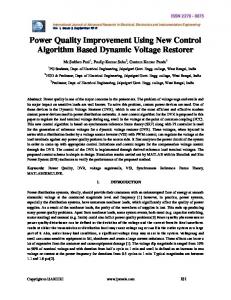
Figure 4. a) The schematic of power circuit used in proposed PWM-AC voltage controller, b) Switching patterns for sector control with PWM ( α = 90° , fs=2kHz)
[email protected]
60
A. ALTINTAŞ
The schematic of power circuit used in the proposed PWMAC voltage controller is given in Fig.4a. A pair of capacitors is placed as snubber capacitors. The circuit topology looks similar to some others proposed before (Shinyama, 2002). The circuit can operate directly from a single-phase line; the voltage across each switch is limited to the line voltage. The series switches S1 and S2 are used to connect or disconnect the load terminals to the supply, that is, they regulate the power delivered to the load. The parallel switches S3 and S4 provide a freewheeling path for the load current to discharge its stored energy when the series switch is turned off. The switching patterns of the controlled switches are decided by the polarity of the source voltage. When the supply voltage is positive, the switches S1 and S3 are driven complementarily and the switches S2 and S4 are fully turned on. If the supply voltage polarity is changed, the switching pattern is reversed. The switching pattern employed in sector control with the conduction angle of 90° and PWM-frequency of 2kHz is given in Fig.4b. The switching pattern can be generated by analog and digital circuitries; each method is used in the simulation studies; analog and digital circuitries are realized by SimCad and Proteus package programs, respectively.
frequency components are no more than one-half the sampling frequency can be accurately digitized. This maximum signal frequency is called Nyquist frequency, and this rule is called Nyquist theorem. When a signal is sampled too slowly, the digitized waveform is distorted. This distortion is called aliasing. It is the result of mixing or beating between the signal frequency and the sampling frequency. As a result of this explanation, to prevent the aliasing in simulation studies, the sampling frequency of 204.8kHz is chosen; it means that a total of 4096 data, which are proper for FFT applications, were employed in one-period time (0.02s). In SimCad package program (PSIM, 2001), firstly, the circuitry given in Fig.4.a was set up; total conduction angle and PWM frequency were adjusted, and the switching pattern was obtained. And then, output-voltage waveform of the converter was measured and stored in a .dat file. This procedure was repeated for each conduction angle. Finally, the stored data in the .dat file were transferred to the Matlab package program. In order to represent harmonics in threedimensional (3D) space, a special Matlab program was developed. The developed program using a FFT built-infunction calculates the harmonics’ amplitudes, and expresses them in 3D space as a function of harmonic frequency and total-conduction angle (Biran and Breiner, 1995; Ingle, 2002; Altintas, 2005). In addition to those, the program computes and sketches the total harmonic distortion, effective value of the output-voltage waveform and amplitude of the fundamental harmonic as a function of the conduction angle.
Simulation Results In the simulation studies, the results obtained from SimCad program are examined. A resistive load is used as a load in the circuitry. When compared to the other load types, the resistive load used with power electronics equipment produces too many harmonics due to not having energystorage property and discontinuity of the load current. That’s why the resistive load is used in the simulation. Because of waveform similarities between phase-angle control and section control, only phase-angle control has been examined. Thus, the proposed method has been applied to the phase-angle and sector control, individually.
Fig.5ab shows the results of 3D harmonic analyses about conventional PWM technique and phase-angle control with PWM, respectively. As seen from Fig.5a, the conventional PWM control produces high order harmonics; high order harmonics are related to switching operation and occur around switching frequency (used as 4kHz in examples) and multiples of switching frequency. In the same way, the proposed method in Fig.5b generates high order harmonics. However, the generated harmonics of the proposed method are fewer and smaller than that of the conventional PWM, especially at lower conduction angles. Fig.6a verifies this inference; the proposed method has lower THD values than the conventional PWM has. Fig.6b shows rms values of the output voltage waveforms; and Fig.6c shows amplitudes of the fundamental harmonics. A disadvantage of the proposed method is to generate a few lower order harmonics at higher conduction angles.
In electrical systems, the harmonic effectiveness of a nonlinear load can be expressed with “Total Harmonic Distortion (THD)”. THD value can be calculated with Eq.1. THD( I ) =
I 22 + I 32 + I 42 + I 52 + ....... I 12
⋅ 100
(1)
where the indices represent harmonic orders. To calculate THD values at different controllers and firing angles, a total of 19 harmonics is taken into account. In according to THD standards, a total of 19 harmonics is enough to obtain an acceptable THD value. The main supply line is considered having a maximum value of 310V, a frequency of 50Hz and not containing any harmonics.
Fig.7a-b shows the results of 3D harmonic analyses about conventional PWM technique and sector control with PWM, respectively. As stated before, the conventional PWM control produces high order harmonics (Fig.7a). In the same way, the proposed method, also, generates high order harmonics (Fig.7b). The generated harmonics of the proposed method are, again, fewer and smaller than that of the conventional PWM, especially at higher conduction angles. Also, Fig.8a verifies this inference; the proposed
For an analog signal to be accurately digitized by an ADC (Analog Digital Converter), it must be sampled at a rate at least two times the highest frequency component in that signal. To put it another way, only signals whose highest
[email protected]
61
A Study on Power Quality Improvement in PWM Controlled AC Voltage Controller
method has lower THD values than the conventional PWM has. Fig.8b shows rms values of the output voltage waveforms; and Fig.8c shows amplitudes of the fundamental harmonics. In the same manner, a disadvantage
of the proposed method is to generate a few lower order harmonics at lower conduction angles.
(a)
(b)
Figure 5. The 3D harmonic analysis results with the switching frequency of 4kHz, a) PWM control only, b) Phase angle control with PWM. 300
350
250
300
%THD
200 150 100
200
Amplitude of 1.H (V)
Effective Value (V)
250
150
100
50 0
250 200 150 100 50
0
50 100 150 Conduction Angle (Degree)
(a)
200
50
0
50 100 150 Conduction Angle (Degree)
(b)
200
0
0
100 150 50 Conduction Angle (Degree)
200
(c)
Figure 6. Comparison of the conventional PWM and the phase-angle control with PWM as a function of α , a) THD values, b) rms values of the output voltage waveforms, c) Amplitudes of the fundamental harmonics (the lines with stars indicate the conventional PWM, the lines with circles indicate the proposed method).
(a) (b) Figure 7. The 3D harmonic analysis results with the switching frequency of 4kHz, a) PWM control only, b) Sector control with PWM.
[email protected]
62
A. ALTINTAŞ
300
250
350 300
%THD
200 150 100
200
Amplitude of 1.H (V)
Effective Value (V)
250
150
100
50 0
250 200 150 100 50
0
50 100 150 Conduction Angle (Degree)
200
50
0
50 100 150 Conduction Angle (Degree)
(a)
(b)
200
0
0
50 100 150 Conduction Angle (Degree)
200
(c)
Figure 8. Comparison of the conventional PWM and the sector control with PWM as a function of α , a) THD values, b) rms values of the output voltage waveforms, c) Amplitudes of the fundamental harmonics (the lines with stars indicate the conventional PWM, the lines with circles indicate the proposed method).
Conclusions The switching mode power conversion gives high efficiency; but the main disadvantage is that harmonics are generated at both the supply and load sides due to the nonlinearity of switches. One of the well known and widespread method for harmonic elimination is PWM technique. In this paper, a novel method for harmonic reduction in PWM-AC voltage controller has been proposed. In the proposed method, AC voltage controllers and conventional PWM-AC voltage controllers have been combined. As the results of this combination, the proposed method has its own merits and demerits: High-order harmonics are effectively suppressed; thus, smaller high-pass LC filter will be used in the filter circuitry. Smaller THD values are obtained (when compared with the conventional PWM technique); as a consequence, power quality improvement is realized. By using classical AC voltage controllers in the proposed method, the switching losses in conventional PWM method are decreased proportionally corresponding to the total conduction angle of AC controllers. The main disadvantage of the proposed method is to generate a few lower order line harmonics at higher conduction angles in phase-angle control with PWM, at lower conduction angles in sector control with PWM. In according to the simulation results, sector control with PWM method has better performance than phase-angle control with PWM method has, because of having lower THD values. Thus, sector control with PWM method is recommended to the relevant people.
References
Arrilaga, J., Bradley, D.A., Bodger, P.S. 1985. Power Systems Harmonics. John-Wiley and Sons, Inc. Norwich, New York/USA, 523 pp. Balci, M.E., Hocaoglu, M.H. 2005. Effects of Source Voltage Harmonic Distortion on Power Factor Compensation in Triac Controlled AC Chopper Circuits. IEEE PEDS, 1119-1204. Biran, A., Breiner, M. 1995. MATLAB for Engineers. Addison-Wesley Publishing Company, Cambridge/ United Kingdom, 668 pp. Bose, B. K. 2002. Modern Power Electronics and AC Drives. Prentice-Hall, Inc. New Jersey/USA, 709 pp. Chicharo, J., Wang, H. 1994. Power System Harmonic Signal Estimation and Retrieval for Active Power Filter Applications. IEEE Trans. on Power, 9, 580-586. Choe, G.H., Wallace, A.K., Park, M.H. 1989. An improved PWM Technique foe AC Choppers. IEEE transactions on power Electronics, 4, 496-505. Haddad, K., Thomas, T., Joos, G., Jaafari, A. 1996. Harmonic reduction in three phase unbalanced systems. CCECE’96, 663-666. Ingle, V.K., Proakis, J.G. 2000. Digital Signal Processing Using Matlab. Bookware Companion Series. Canada, 418 pp.
Altintas, A. 2005. A Comparative Study on AC Voltage Controllers in Terms of Harmonic Effectiveness. Erciyes University, Journal of the Institute of Science and Technology, 21, 79-86.
Kazmierkowski, M.P., Krishnan, R., Blaabjerc, F. 2002. Control in Power Electronics. Academic-Press, Inc. California/USA, 518 pp.
[email protected]
63
A Study on Power Quality Improvement in PWM Controlled AC Voltage Controller
Min, B.D., Kwon, B.H. 1998. Novel PWM line conditioner with fast output voltage control. IEE, Proc.-Electr. Power Appl., 145, 85-91. Nabil, A.A., Amei, K., Sakui, M. 1999. A New Configuration of Single-Phase Symmetrical PWM AC Chopper Voltage Controller. IEEE Transactions on Industrial Electronics, 46, 942952.
Shinyama, T., Ueda, A., Torii, A. 2002. AC Choppers Using Four Switches. IEEE, 1056:1060. Springob, L. 1999. Power Electronics and Drive Technology. Leybold Didactic GMBH. Germany, 399 pp.
Youm, J.H., Kwon, B.H. 1999. Switching Technique for Current-Controlled AC-to-AC Converters. IEEE Transactions on Industrial Electronics, 46, 309-318.
Nabil, A.L.A. 1997. Improved Circuit of AC Choppers for Single-Phase Systems. IEEE, 907-912. Powersim, 2001. PSIM user manual version 5.0, PSIM Inc. Woburn, MA/U.S.A.
[email protected]
64