52
Int. J. Industrial Electronics and Drives, Vol. 1, No. 1, 2009
Power quality improvement in vector controlled induction motor drive employing multipulse AC-DC converters S. Gairola* Department of Electronics & Communication Engg., IMS Engineering College, Ghaziabad, NH-24, Adhyatmik Nagar, Ghaziabad (U.P.) 201009, India E-mail:
[email protected] *Corresponding author
B. Singh Department of Electrical Engineering, Indian Institute of Technology, Delhi, Hauz-Khas, New Delhi-110016, India E-mail:
[email protected] Abstract: In this paper, the power quality performance is investigated from hardware implementation of vector controlled induction motor drive (VCIMD) having multipulse AC-DC converter at front-end. The power quality issues are analysed for 12-pulse, 24-pulse and 40-pulse non-isolated, uncontrolled multipulse AC-DC converters. The vector control of a voltage source inverter (VSI) fed induction motor drive is modelled in MATLAB environment using Simulink and Power System Blockset toolboxes. The results obtained from the simulations are presented along with the hardware test results. It is observed that the AC mains current THD having value less than 3% in VCIMD is possible employing multipulse AC-DC converters. Keywords: multipulse converter; vector controlled induction motor drive; VCIMD; power quality; zigzag-connection; polygon connection. Reference to this paper should be made as follows: Gairola, S. and Singh, B. (2009) ‘Power quality improvement in vector controlled induction motor drive employing multipulse AC-DC converters’, Int. J. Industrial Electronics and Drives, Vol. 1, No. 1, pp.52–63. Biographical notes: Sanjay Gairola received his BE in Electrical Engineering from M.N.R. Engineering College, Allahabad in 1991 and his MTech and PhD degrees from Indian Institute of Technology (IIT), New Delhi, in 2001 and 2008, respectively. After working in industry for sometime, he joined KIET, Ghaziabad in 1997 as a Lecturer. At present, he is a Professor in IMS Engineering College, Ghaziabad (U.P.). He is a Life Member of Indian Society for Technical Education (ISTE). His field of interest includes power electronics, electric machines and drives. Bhim Singh received his BE (Electrical) from the University of Roorkee, India in 1977 and his MTech and PhD degrees from the Indian Institute of technology (IIT), New Delhi, in 1979 and 1983, respectively. At present, he is a Professor in the Department of Electrical Engineering at IIT Delhi. His field of interest includes power electronics, electrical machines and drives, active filters, static VAR compensator, analysis and digital control of electrical machines. He is a Fellow of Indian National Academy of Engineering (INAE) and member of many prestigious technical international societies.
1
Introduction
The non-isolated uncontrolled AC-DC converters are commonly used in adjustable speed drives (ASDs) such as vector/direct-torque controlled induction motor drive, DC motor drive, etc. (Bose, 1998; Wu, 2006; Paice, 1996). It is important to consider the power quality issues in these applications to justify the need for multipulse AC-DC converters. Variable frequency induction motor drives
Copyright © 2009 Inderscience Enterprises Ltd.
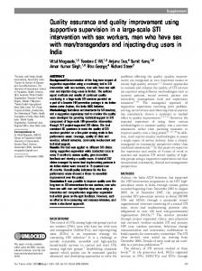
(VFIMDs) are commonly realised using the techniques of scalar control, vector control (VC) and direct torque control (DTC). Vector controlled induction motor drives (VCIMD), shown in Figure 1, are extensively used in industry (Singh et al., 2006a, 2006b, 2006c, 2006d; Choi et al., 1997) and almost every manufacturer of the drive has developed it. DTC induction motor drives originally developed by ABB (Bose, 1998) are also equally popular now (Bose, 1998).
Power quality improvement in vector controlled induction motor drive employing multipulse AC-DC converters However, it is a main feature of almost all of these industrial drives that they cause injection of harmonics into AC-mains when these are fed from six-pulse AC-DC converters. IEEE Standard-519 (1992) has recommended that the value of AC-mains current THD must be less than 8%. Passive or active filters are commonly used at the input of converters, which have a power rating of more than 30% of the load, complex in design, costly and control. Therefore, to solve the problem of poor power quality, multipulse converters (Singh and Gairola, 2007; Singh et al., 2008) is an attractive alternative, which not only improves THDi (Wu, 2006; Paice, 1996; Singh et al., 2006a, 2006b, 2006c, 2006d, 2008; Choi et al., 1997; Singh and Gairola, 2007, 2008) at the input but it is also simple in design, cheap and need no control. The VC of a voltage source inverter (VSI) fed induction motor drive is modelled in MATLAB environment using Simulink and Power System Blockset toolboxes. To validate the simulated results, a VFIMD is implemented using a dSPACE DS 1104 based DSP system. For implementation, a three-phase 10-hp induction motor is considered and converter-inverter system is fed from a three-phase supply system. Simulated and test results obtained on the developed VFIMD are presented and discussed in detail. Figure 1
A six-pulse diode bridge fed VCIMD and controller
2.1 Configuration of multipulse AC-DC converters It is seen that these multipulse AC-DC converters are employed in many applications and have different ratings, control strategies and configurations (Singh et al., 1996a, 1996b, 1996c, 1996d, 2008; Choi et al., 1997; IEEE Standard-519, 1992; Singh and Gairola, 2007, 2008). However, the VFIMDs are the most popular drives and act as main work horse for the industry. The VCIMD fed from the six-pulse converter does not require magnetics but have power quality problems and therefore the proposed multipulse AC-DC converters may be employed, which are as follows. 1
12-pulse AC-DC converters: A zigzag connected autotransformer (Singh and Gairola, 2007) based 12-pulse AC-DC converter is used to feed VCIMD as shown in Figure 2(a). Figure 2(b) shows the autotransformer winding arrangement and its connection to the supply and two-phase staggered bridges, Bridge 1 and Bridge 2. The zigzag connection of autotransformer is preferred as this gives the lowest magnetic ratings and inherently blocks the flow of zero sequence current components thereby taking care of small unbalance of voltages. The length of windings in Figure 2(b) as a fraction of input phase voltage is given as: K1 = 0.5773 and K2 = 0.2679.
Figure 2
(a) A 12-pulse AC-DC converter for VCIMD load using zigzag transformer, (b) zigzag autotransformer winding arrangement for 12-pulse AC-DC converter
(a)
2
53
System configuration
In this paper, to solve the problems of poor power quality, multipulse AC-DC converters are studied with VCIMD. In this section, the design of various multipulse converter configurations is explained and the control strategy employed for VCIMD implementation is also discussed.
(b)
54
S. Gairola and B. Singh
Figure 3
Zigzag connected autotransformer based configuration for 24-pulse AC-DC converter employing hybrid technique (hybrid of phase staggering and ripple reinjection technique)
Figure 4
(a) A polygon wound autotransformer based 40-pulse AC-DC converter fed VCIMD load (b) autotransformer winding arrangement and its phasor diagram
2
24-pulse AC-DC converter: Figure 3 shows the zigzag connected autotransformer based 24-pulse AC-DC converter that employs pulse multiplication in the 12-pulse converter configuration. The pulse multiplication is achieved using an interphase reactor that is tapped with two diodes (D1 and D2). It is observed from the literature (Singh et al., 2006a, 2006b, 2006d, 2008; Choi et al., 1997; IEEE Standard-519, 1992; Singh and Gairola, 2008) that the various autotransformer configurations such as star or polygon or extended-delta connected transformer based converters for pulse multiplication also require a ZSBT to block the zero sequence currents that has magnetic power rating of about 7.5% of load rating. However, the zigzag connected autotransformer inherently blocks the zero sequence currents and therefore this configuration do not require a ZSBT to prevent inter bridge currents. This makes the configuration an ideal choice as the proposed configuration, which has reduced number of components and therefore reduced magnetics rating and increased reliability. The diode tapped interphase reactor has its three segments in ratio of 0.2475: 0.5086: 0.2475.
3
40-pulse AC-DC converter: Figure 4(a) shows the 40-pulse AC-DC converter configuration that has a polygon wound autotransformer (Singh and Gairola, 2008), two 5-leg diode bridges, a ZSBT and a diode tapped IPR feeding a VCIMD. The winding arrangement and phasor diagram of this autotransformer is shown in Figure 4(b).
(a)
2.2 Configuration of VCIMD fed from multipulse AC-DC converters This section presents the mathematical modelling of the various blocks in the VCIMD. A MATLAB model is developed to investigate the simulated performance of VCIMD. The developed model of VCIMD is shown in Figure 5(a). VCIMD constitutes the following main block as shown in Figure 1.
(b)
1
PI speed controller
2
field weakening controller
3
current controller
4
VSI
5
an induction motor.
Power quality improvement in vector controlled induction motor drive employing multipulse AC-DC converters Figure 5
(a) MATLAB model of a 6-pulse AC-DC converter fed VCIMD load (b) MATLAB model of zigzag connection based 24-pulse (12 × 2) AC-DC converter with VCIMD load (c) MATLAB model of autotransformer for the zigzag 12-pulse and 24-pulse (12 × 2) AC-DC converter simulation (d) MATLAB model of 40-pulse AC-DC converter for feeding VCIMD (see online version for colours)
55
2.2.1 Vector controlled induction motor drive The VC of an induction motor is used to achieve high level of performance due to its well-known advantages. The block diagram of the VCIMD is shown in Figure 1. The closed loop PI speed controller compares the reference speed (ωr∗) with motor speed (ωr) and generates reference torque Teref(n) (after limiting it to a suitable value). Teref (n) = Teref (n −1) + K p {ωe( n )− ωe( n −1) } + K I ωe( n )
(1)
where, Teref(n) and Teref(n–1) are the output of the PI controller (after limiting it to a suitable value) and ωe(n) and ωe(n–1) refer to speed error at the nth and (n–1)th instants. Kp and KI are the proportional and integral gain constants. In the rotor-flux-oriented reference frame, the d-component of the stator current reference vector idm* is obtained as: idm * = i mr + τr ( Δi mr / ΔT )
(2)
The q-component of the stator current reference vector iqm* is obtained from the output of the PI controller as: (a)
iqm * = T * / ( K i mr )
(3)
K = ( 3 / 2 )( P / 2 ) {M / (1 + σr )}
(4)
The d-component idm* and q-component iqm* of the stator current from the inverter current reference vector in rotor flux-oriented reference frame, which is then converted to the stationary reference frame using following relations:
(b)
ω2 * = iqm * / ( τr i mr )
(5)
ψ ( n ) = ψ ( n –1) + ( ω2 * + ωr ) ΔT
(6)
imr is the magnetising current, ω2* is the slip speed of the rotor, ωr is the angular velocity of rotor. P, M and σr are the number of poles, mutual inductance and rotor leakage factor respectively, ψ(n) and ψ(n–1) are the value of rotor flux angles at nth and (n–1)th instants respectively and ΔT is the sampling time. These currents (idm*, iqm*) are in synchronously rotating reference frame and these are converted into stationary reference frame three-phase currents (ima*, imb*, imc*) as given below: i ma * = −iqm * sinψ + idm * cosψ (c)
{(
C1
1
C2
In1 Out3
VA
Out4
2
diffren polyn Out5 In2 auto-Xer
Conn3 C7
Out8
Bridge1 1+ +3
In3
Out9
VC
C2
1 C6
4
ZSBT
C4 C7 C5
Out10
Polygon Autotransformer for 40-pulse converter
3
2+ +4 2
C3
Bridge2
(d)
4 VDC+
Diode Tapped IPR
C5
C1 Out7
Conn1 Conn2
Out6
VB
3
C6
C3 C4
)
(
)
}
imb * = −cosψ + √ 3sinψ idm * + sinψ + √ 3cosψ iqm * / 2 (8)
Out1 Out2
(7)
VDC5
i mc * = − ( i ma * + i mb *)
(9)
ima*, imb* and imc* are the three-phase reference currents. These three-phase reference currents generated by the vector controller are compared with the sensed motor currents (ima, imb and imc). The calculated current errors are: iek = i mk * − i mk , where k = a, b, c.
(10)
56
S. Gairola and B. Singh
These current errors are amplified to determine the switching functions (Sa, Sb, Sc) used in equations (11)–(13) and fed to the PWM current controller, which controls the on and off periods of different switches in the VSI. The VSI generates the PWM voltages being fed to the motor to develop the torque for running the motor at a desired speed under required loading conditions. The inverter voltages can be derived from the switching functions Sa, Sb, Sc as given below: vas = ( Vdc / 3) (2Sa − Sb − Sc )
(11)
v bs = ( Vdc / 3) (−Sa + 2Sb − Sc )
(12)
v cs = ( Vdc / 3) (−Sa − Sb + 2Sc )
(13)
where Sa, Sb, Sc are the switching functions (which are either one or zero), vas, vbs, and vcs are the voltages of phases a, b and c respectively. The direct and the quadrature axis stator voltages can be obtained from three-phase voltage equations as vsD = (1/ 3) (v ba – vac )
(14)
vsQ = ( −1/ 3) (vac + v ba )
(15)
where, v ba = v bs – vas , vac = vas − vcs Thus, using the DC link voltage and the switching functions of each of the inverter legs, the direct and the quadrature axis voltages in the stationary reference frame can be obtained from the above equations. Based on these expressions, the models are built in MATLAB environment using Simulink and SimPowerSystems toolboxes as shown in Figure 5 and the simulations are carried out employing discrete solver. A three-phase induction motor fed from multipulse AC-DC converters and it is controlled using vector control technique. The details of the motor parameters are given in Appendix.
3
Hardware development of VFIMD fed from different AC-DC converters
The real time implementation of a three-phase 10-hp induction motor drive in VC is carried out using a fast digital signal processor dSPACE DS1104 controller to validate the simulation models, as shown in Figure 6. It mainly consists of a MPC8240 processor with PPC603e core and on-chip peripherals. This is a 64-bit floating point processor with 250 MHz central processor unit (CPU) clock frequency. It also consists of a slave DSP TMS320F240 of Texas Instruments. This controller consists of dSPACE DS1104 controller, interfacing circuits namely the speed and current sensing circuits, PWM pulse isolation and amplification circuit, VSI and power supplies. The test bench mainly consists of dSPACE DS1104 controller, interfacing circuits namely the speed and current sensing circuits, PWM pulses isolation and amplification circuit, VSI and power supplies.
Figure 6
DSP controller and various interfacing arrangement for VFIMD system developed in the laboratory
3.1 DSP dSPACE DS1104 controller DSP controller based on DS1104 from dSPACE consists of dSPACE card as master processor and TMS320F240 as slave processor. The arrangement of this dSPACE DSP controller and various interfacing for VCIMD system is developed in the laboratory and the peripherals of the processor used for the implementation are as follows: •
4-channel, 12-bit analogue-to-digital converter (ADC) is used to input the sensed motor winding currents of two phases. Similarly, the rotor speed is also sensed through an ADC channel.
•
6-channels of PWM output are used to take out the PWM signals from dSPACE processor. Digital signal processor TMS320F240 slave processor is involved for giving continuous PWM signals to the driver of the IGBT’s of VSI driving the induction motor.
3.2 Current sensing and scaling circuit Two-phase currents of the motor namely, ima and imb are sensed using ABB make Hall effect current sensors (EL50P1BB). The current sensor gives an output voltage signal, which is proportional to the input sensed current. The turn ratio of these current sensors is 1/1000. The rated maximum current is 50 A and the output current is 50 mA. Two conductor turns are wound around the current sensor to obtain the output signals with the range of ±10 V as per specification of ADC channels of dSPACE-DSP system.
3.3 Speed sensing and scaling circuit The output of a DC tachogenerator coupled on shaft of the induction motor is used for sensing the rotor speed. The output varies between +80 V to –80 V for maximum forward and reverse speed rotation. The ADC of dSPACE-DSP system can have maximum input signal of ±10 V therefore, the speed voltage signal from the tachogenerator is scaled down to this range using a simple potential divider and saturation circuit.
Power quality improvement in vector controlled induction motor drive employing multipulse AC-DC converters
3.4 Voltage source inverter A Semikron make, 25 kVA VSI module is chosen for feeding VCIMD in this investigation. It consists of a three-phase diode rectifier (MD8TU6016) of 80 A rating. It also consists of three-legs of half-bridge IGBT modules (SKM100GB128DN) of Semikron make, mounted on heat sink to constitute a VSI. This module is capable of operating up to 20 kHz switching frequency and have inbuilt thermal protection. To protect the devices from high dv/dt transients, snubber capacitors of 0.2 µF have also been connected across the VSI. A driver module SKH122A having inherent dead time of 3 µsec. has been chosen to feed pulses to the semiconductor switches (IGBT’s). The driver is connected to a controlled +15 V supply voltage. In case of short circuit or too low supply voltage (less than 13 V), the integrated error memory is set and an error signal is generated. The integrated short pulse suppression avoids very short switching pulse at the power semiconductor caused interference by high frequency pulses at the driver input signals. The diode rectifier is disconnected from the module to enable multipulse AC-DC converter investigations in this work.
3.5 Gating signal isolation and amplification circuit The output PWM signals from the DSP can be of maximum 5 V, whereas, the driver circuit of the inverter requires an input voltage of 15 V, therefore, the output of the PWM needs to be boosted before it is applied to the inverter’s Table 1
57
driver. The driver SKH122B is designed with isolation up to 2.5 kV; however, to protect dSPACE from inverter spurious signals and from safety as well as reliability point of view, separate isolation is provided through opto-coupler 6N136. This opto-coupler is suitable for high speed applications and needs supply voltage of 0–15 V and base current of isolating transistor is 5 mA.
4
Results and discussions
The simulated results using developed MATLAB models are obtained for various MPC configuration fed VCIMD and varying loads. These results are discussed in this section for VCIMDs as these are also used for validation by experimental prototypes.
4.1 Simulated results The MATLAB model of a six-pulse AC-DC converter fed VCIMD [Figure 5(a)] is used to study the dynamic response of 10 hp induction motor. Various multipulse converters are shown in Figures 2–4. The current waveform of six-pulse AC-DC converter fed VCIMD at full-load along with the AC mains current harmonic spectrum and THDi is shown in Figure 7(a). The THD of AC mains current is observed to be 76.83% and 31.29% at light load and full-load given in Table 1.
Comparison of power quality parameters of 6-pulse with 12-pulse and 24-pulse AC-DC converters fed VCIMD
% THD Topology of Vac
AC mains current Iac (A)
% THD of Iac at
Distortion factor Displacement factor DF DPF
Power factor PF
DC voltage (V)
Light
Full
Light
Full
Light
Full
Light
Full
Light
Full
Light
Full
Load
Load
Load
Load
Load
Load
Load
Load
Load
Load
Load
Load
6-pulse
10.58
8.701
19.12
74.68
31.4
0.9110
0.9491
0.9798
0.9768
0.8926
0.9271
552.9
542.8
12-pulse
5.224
8.343
18.54
9.743
9.104
0.9948
0.9944
0.9891
0.9901
0.9840
0.9846
574.1
568.0
24-pulse
3.693
4.202
14.56
6.384
5.017
0.9972
0.9983
0.9991
0.9981
0.9963
0.9964
587.2
584.8
40-pulse
3.138
3.971
13.61
2.226
3.851
0.999
0.9991
0.9972
0.9994
0.9984
0.9985
632.1
634.9
The simulations are carried out with different multipulse AC-DC converters for this VCIMD and investigated in detail. The AC current waveform, its harmonic spectrum and THD for 12-pulse AC-DC converter fed VCIMD in Figure 7(b). The waveforms of 24-pulse AC-DC converter employing ripple re-injection technique are shown in Figure 7(c). The value of AC-mains current at full-load is found to be 5.02%, which meets the IEEE 519 Standard requirement. THDi of AC-mains current waveform of 40-pulse AC-DC converter fed VCIMD is observed to be
2.226% only, as shown in Figure 7(d). It can be observed that the power quality improves, with increasing pulse numbers. This 40-pulse converter employs an interphase transformer (IPT) and ZSBT besides the main autotransformer at the front-end and the ratings of the magnetics for them is given in Table 2 along with AC-mains current THDi for comparison of these multipulse AC-DC converters. The zigzag connection based converter configurations is found to have a lower magnetic ratings than the rating of converters reported by researchers.
58 Figure 7
S. Gairola and B. Singh (a) Input current waveform and harmonic spectrum of six-pulse AC-DC converter fed VCIMD at full-load (b) input current waveform and harmonic spectrum of zigzag connection with 12-pulse AC-DC converter fed VCIMD at full-load (c) input current waveform and harmonic spectrum of zigzag connection with pulse doubling 24-pulse AC-DC converter fed VCIMD at full-load (d) input current waveform and harmonic spectrum of polygon connected 40-pulse AC-DC converter fed VCIMD at full-load
Figure 7
(a) Input current waveform and harmonic spectrum of six-pulse AC-DC converter fed VCIMD at full-load (b) input current waveform and harmonic spectrum of zigzag connection with 12-pulse AC-DC converter fed VCIMD at full-load (c) input current waveform and harmonic spectrum of zigzag connection with pulse doubling 24-pulse AC-DC converter fed VCIMD at full-load (d) input current waveform and harmonic spectrum of polygon connected 40-pulse AC-DC converter fed VCIMD at full-load (continued)
(a)
(d) Table 2
Main transformer rating % of load
Interphase transformer rating % of load
ZSBT rating % of load
6-pulse
-
-
-
12-pulse
19.31
7.42
-
24-pulse
26.44
1.72
-
40-pulse
53.72
0.71
2.83
Topology
(b)
Comparison of magnetic ratings of six-pulse with 12pulse, 24-pulse and 40-pulse AC-DC converters fed VCIMD
% Total magnetic rating of load
THDi %
6-pulse
-
31.4
12-pulse
26.73
9.10
24-pulse
28.16
5.01
40-pulse
57.26
2.2
Topology
4.2 Hardware implementation results For validation of simulated results of multipulse converter supplying VCIMD, an implementation of these converters is realised on a 10-hp induction motor. Test results are presented for various operating conditions such as starting, steady state and load perturbation for a 10-hp induction motor drive controlled using VC technique. (c)
Power quality improvement in vector controlled induction motor drive employing multipulse AC-DC converters
the motor running at speed of 0.8 p.u. (1200 rpm), a load torque equal to the rated torque is applied on its shaft. The load is applied by loading the DC generator coupled on the shaft of the induction motor. Sudden application of the load causes an instantaneous drop in the rotor speed and the output of PI speed controller increases the reference torque, thus increasing the developed torque (Te) and causing the motor speed to settle to its reference value with increased winding currents. It is seen that the motor speed settles to its reference value within short time without much overshoots or undershoots.
The response under various conditions is also obtained from developed hardware for six-pulse and multipulse AC-DC converter fed VFIMD and shown in Figures 8–15. Test results are recorded using 54624A Agilent make, 4-channel, digital storage oscilloscope (DSO) and described as follows. Power quality parameters are also recorded using Fluke 43B power analyser and results are shown in Figure 9, 11, 13 and 15 under steady state for different loads.
4.2.1 Performance of VCIMD fed from 6-pulse ACDC converters The performance of a 10-hp induction motor drive is simulated as well as implemented using indirect VC technique. Different tests have been conducted with PWM switching frequency kept at 10 kHz and the test results are presented in Figures 8–9. The set of curves consists of AC supply voltage, AC mains current, rotor speed/ DC link voltage and motor current. The waveforms are shown during starting, steady state and load perturbations on VCIMD. •
•
Starting: The starting dynamics for 10-hp induction motor drive are shown in Figure 8(a). The reference speed is kept at 0.6 p.u. (865 rpm), with a torque limit at twice the rated value. It is seen that the starting current is also limited during the motor speeding up to the set reference speed. When the speed error becomes zero, the winding currents reduce to no-load value and the developed torque also reduces. It can be observed that the starting time is around 0.8 sec. at 0.6 p.u. speed. It can be observed that as the motor speeds up, the frequency of stator currents also increases to accelerate the motor to high speed. Steady state response: Figure 8(b) shows the steady state response of the induction motor drive. Figure 9 shows AC mains current waveform, harmonic spectra and THD at three different loads. The THD of AC mains current is found to vary between 74% and 29.2% as the load is varied from light-load to full-load in simulated and test results. Figure 9 shows test results of IM fed from six-pulse AC-DC converter under steady state recorded on power analyser. It shows voltage and current waveforms, harmonic spectrum and THD of AC mains current at a load of 367W, 3.27 kW and 6.67 kW. Figure 8(a) shows test result waveforms of supply voltage, AC mains current, speed and motor current during starting of VCIMD fed from six-pulse AC-DC converter. Figure 8(b) shows test result waveforms of supply voltage, AC mains current, DC link voltage and motor current during steady state for VCIMD fed from 6-pulse AC-DC converter.
•
Load application: Figure 8(c) shows the response waveforms of a 10-hp induction motor drive during load application. In this waveform, it is observed that
59
•
Load removal: Figure 8(d) shows the dynamics during sudden load removal on the vector controlled 10-hp induction motor drive. The waveforms of supply voltage, supply current, motor speed and the motor winding current can be seen. When the induction motor is running at 0.8 p.u. suddenly the load is removed from its shaft. The sudden removal of load results in small overshoot in the motor speed, this reduces the PI controller output leading to reduction in motor speed and finally it settles to the reference value. The experimental waveforms match the simulated results, thus validating the simulation model.
Figure 8
(a) Starting of 7.5 kW induction motor with six-pulse AC-DC converter at no-load to rated speed-supply voltage waveform, input current, speed, motor current of phase A (b) test results of IM fed from six-pulse AC-DC converter under steady state (c) test result waveforms of supply voltage, DC link voltage, speed and motor current during load application for VCIMD fed from six-pulse AC-DC converter (d) test result waveforms of supply voltage, DC link voltage, speed and motor current during load removal for VCIMD fed from six-pulse AC-DC converter
(a)
(b)
60 Figure 8
S. Gairola and B. Singh (a) Starting of 7.5 kW induction motor with six-pulse AC-DC converter at no-load to rated speed-supply voltage waveform, input current, speed, motor current of phase A (b) test results of IM fed from six-pulse AC-DC converter under steady state (c) test result waveforms of supply voltage, DC link voltage, speed and motor current during load application for VCIMD fed from six-pulse AC-DC converter (d) test result waveforms of supply voltage, DC link voltage, speed and motor current during load removal for VCIMD fed from six-pulse AC-DC converter (continued)
4.2.2 Power quality improvements in VCIMDs The performance of VCIMD is also investigated with multipulse AC-DC converters. It is observed to improve VCIMDs in terms of power quality. The simulation results have shown an improved power quality at AC mains and the test results are obtained to validate it. Test results for 12-pulse, 24-pulse and 40-pulse AC-DC converters fed VCIMD are demonstrated here to validate the advantage of multipulse AC-DC converters. Test results are shown in Figures 10–15 for different cases. Figure 10 (a) Starting of VCIMD fed from 12-pulse AC-DC converter at no-load showing – supply voltage waveform, input current, DC link voltage and a motor current of phase A (b) test results of IM fed from twelve-pulse AC-DC converter under steady state (c) test result waveforms of supply voltage, DC link voltage, speed and motor current during load removal for VCIMD fed from 12-pulse AC-DC converter
_ (c)
(a)
(d) Figure 9
Test results of IM fed from six-pulse AC-DC converter under steady state showing power analyser recorded waveform, harmonic spectrum and THD of AC mains current at three loads
(b)
(a)
(b)
(c) (c)
Power quality improvement in vector controlled induction motor drive employing multipulse AC-DC converters The detailed design and development of multipulse (12, 24 and 40-pulse) AC-DC converters are described in detail in the literature (Singh and Gairola, 2007, 2008; Singh et al., 2008). The increase in number of steps in current waveform is observed in these AC-DC converters. It can be observed from all these test results that with the increasing pulse number, the power quality at AC mains improve, however, a 24-pulse AC-DC converter meets the power quality requirements as specified by Standard IEEE-519.
4.2.2.1 Performance of VCIMD fed from 12-Pulse AC-DC converter
4.2.2.2 Performance of VCIMD fed from 24-pulse AC-DC converter The performance of a 10-hp induction motor drive fed from zigzag connected autotransformer employing ripple re-injection technique to realise 24-pulse AC-DC converter is implemented using indirect VC technique. The test results are presented in Figures 12–13. Figure 12 (a) Starting of 7.5 kW induction motor fed from 24-pulse AC-DC converter – supply voltage waveform, input current, DC link voltage, motor current of phase A (b) test results of IM fed from twenty four-pulse AC-DC converter under steady state
The performance of a 10-hp induction motor drive is implemented using 12-pulse AC-DC converter fed VCIMD. Different tests have been conducted and the test results are presented in Figures 10 to 11. The set of curves consists of AC supply voltage, AC mains current, rotor speed/DC link voltage and motor current. The starting dynamics for 10-hp induction motor drive are shown in Figure 10(a). It can also be observed that the input current is a 12-step waveform. Figure 11 shows the steady state response of the induction motor drive at loads of 1.05 kW, 3.57 kW and 4.99 kW. It shows AC mains current waveform, harmonic spectra and THD at these loads. The THD is found to be around 11.5% as the load is varied. Under loaded condition in steady state, the response of the VCIMD is shown in Figures 11 (b) and 11(c). This shows that the AC mains current THD has improved in comparison to that of six-pulse AC-DC converter fed VFIMD. Figure 10(c) shows the dynamics during sudden load removal on the vector controlled 10-hp induction motor drive. When the induction motor is running at 0.8 p.u., suddenly the load is removed, however, the input current waveform remains 12-step and the magnetic rating employed is only 26.73%. Figure 11 Test results of VCIMD fed from zigzag connected 12-pulse AC-DC converter under steady state showing power analyser recorded waveform and harmonic spectrum and THD of AC mains current at three loads
(a)
(b)
(c)
61
(a)
(b) Figure 13 Test results of VCIMD fed from zigzag connected 24-pulse AC-DC converter under steady state showing power analyser recorded waveform and harmonic spectrum and THD of AC mains current at three loads
(a)
(b)
(c)
62
S. Gairola and B. Singh
Figure 14 (a) Starting of 7.5 kW induction motor fed from 40-pulse AC-DC converter – supply voltage waveform, input current, DC link voltage, motor current of phase A (b) test results of IM fed from 40-pulse AC-DC converter under steady state (c) test result waveforms of supply voltage, DC link voltage, speed and motor current during load application for VCIMD fed from 40-pulse AC-DC converter (d) test result waveforms of supply voltage, DC link voltage, speed and motor current during load removal for VCIMD fed from 40-pulse AC-DC converter
The set of curves consists of AC supply voltage, AC mains current, rotor speed/DC link voltage and motor current. The starting dynamics for 10-hp induction motor drive are shown in Figure 12(a). The reference speed is kept at 0.6 p.u. (865 rpm), with a torque limit at twice the rated value. It is seen that the starting current is also limited during the motor speeding up to the set reference speed. The waveform of AC mains current remains 24-step and almost sinusoidal during starting, steady state and load perturbations. Figure 12(b) shows the steady state response of the induction motor drive at full load. Figure 13 shows AC mains current waveform, harmonic spectra and THD at three loads –1.15 kW, 2.37 kW and 5.18 kW. The THD is found to vary between 7.3% and 5.9% as the load is varied from light to full-load in simulations and test results.
4.2.2.3 Performance of VCIMD fed from 40-pulse AC-DC converters
(a)
(b)
The performance of a 10-hp VCIMD, fed from polygon connected 40-pulse AC-DC converter is implemented in the laboratory, is presented in Figures 4–5. The starting dynamics for 10-hp induction motor drive are shown in Figure 14(a) while Figure 14(b) shows the steady state response of the induction motor drive at load. Figure 15 shows AC mains current waveform, harmonic spectra and THD at a load of 0.5 kW, 1.25 kW and 2.5 kW. The THD of AC mains current is found to vary between 3.2% and 2.2% as the VCIMD load is varied from light to full-load. Figure 14(c) shows the response waveforms of a 10-hp induction motor drive during load applications. The waveforms of supply voltage, supply current, motor speed and the motor winding current can be seen. The AC mains current waveform can be observed to remain 40-pulse during load perturbations and the input AC current is sinusoidal with a THD value of around 2.2%, making it most suitable for applications with a need of stringent power quality limits such as military applications. Figure 15 Test results of IM fed from polygon connected 40-pulse AC-DC converter under steady state showing power analyser recorded waveform and harmonic spectrum and THD of AC mains current
(c)
(a) (d)
(b)
(c)
Power quality improvement in vector controlled induction motor drive employing multipulse AC-DC converters
5
Conclusions
A VCIMD employing multipulse AC-DC converters at front-end has been investigated for comparison of power quality issues with six-pulse AC-DC converter fed drive. It has been observed that the zigzag transformer based 24-pulse AC-DC converters meets all the power quality requirements of IEEE Standard 519, has total magnetic rating of value 28.16% only. Moreover, it requires minimum number of components as no ZSBT is employed. The 40-pulse AC-DC converter meets more stringent power quality requirements and THD of AC mains current as low as 2.2% is achieved, which may be difficult to obtain using active filters. The improvement in power quality parameters in zigzag connection based 12 and 24-pulse and polygon connection based 40-pulse multipulse AC-DC converters have validated their advantage and need for the numerous applications.
Singh, B., Gairola, S., Singh, B.N., Chandra, A. and Al-Haddad, K. (2008) ‘Multipulse AC-DC converters for improving power quality: a review’, IEEE Trans. on Power Electronics, January, Vol. 23, No. 1, pp.260–281. Wu, B. (2006) High-Power Converters and AC Drives, IEEE Press, Wiley-Interscience, 2006.
Appendix Motor and controller specifications Three-phase squirrel cage induction motor-10 hp (7.5kW), 3-phase, 4 Pole, Y-connected, 415 V, 50 Hz Rated current = 14.5 A RS = 1.0 ohm, Rr = 0.76 ohms Xls = 0.77 ohms, Xlr = 0.77 ohms, Xlr = 0.77 ohms, Xlm = 18.84 ohms J = 0.1 kg-m2
References Bose, B.K. (1998) Modern Power Electronics and AC Drives, Pearson Education, Singapore. Choi, S., Lee, B.S. and Enjeti, P.N. (1997) ‘New 24-pulse diode rectifier systems for utility interface of high-power AC motor drives’, IEEE Transactions on Industry Applications, Mar/April, Vol. 33, No. 2, pp.531–541. IEEE Standard-519 (1992) IEEE Guide for Recommended Control and Reactive Compensation of Static Power Converters. Paice, D.A. (1996) Power Electronic Converter Harmonics: Multipulse Methods for Clean Power, IEEE Press. Singh, B. and Gairola, S. (2007) ‘Pulse multiplication in auto-transformer based AC-DC converter using zigzag connection’, Journal of Power Electronics, Korea, July, Vol. 7, No. 3, pp.191–202. Singh, B. and Gairola, S. (2008) ‘A novel 40-pulse AC-DC converter for vector controlled induction motor drive’, IEEE Transactions on Energy Conversion, June, Vol. 23, No. 2, pp.403–411. Singh, B., Bhuvaneswari, G., Garg, V. and Gairola, S. (2006d) ‘Pulse multiplication in AC-DC converters for harmonic mitigation in vector-controlled induction motor drives’, IEEE Transactions on Energy Conversion, June, Vol. 21, No. 2, pp.342–352. Singh, B., Bhuvaneswari, G. and Garg, V. (2006a) ‘Multipulse improved-power-quality AC–DC convertors for vector-controlled induction-motor drives’, IEE Proc.-Electr. Power Appl., January, Vol. 153, No. 1, pp.88–96. Singh, B., Bhuvaneswari, G. and Garg, V. (2006b) ‘Power-quality improvements in vector-controlled induction motor drive employing pulse multiplication in AC–DC converters’, IEEE Transactions On Power Delivery, July, Vol. 21, No. 3, pp.1578–1586. Singh, B., Bhuvaneswari, G. and Garg, V. (2006c) ‘T-connected autotransformer-based 24-pulse AC–DC converter for variable frequency induction motor drives’, IEEE Transactions On Energy Conversion, September, Vol. 21, No. 3, pp.663–672.
63
PI speed controller: Kp=10, KI = 0.17.